Trinahome N6052T User manual

–T Series (N6052T)
Solar Battery Hybrid System
Installation Manual
Version 1.1

N6052T Solar Battery Hybrid System Installation Manual
Content
1. Safety.................................................................................................................... 1
1.1 How to Use This Manual.................................................................................................. 1
1.2 Safety Rules ..................................................................................................................... 1
1.3 Warning Notices Affixed to the Device ........................................................................... 2
1.4 Important Safety Information ......................................................................................... 3
1.5 Disposal ........................................................................................................................... 4
1.6 Exclusion of Liability ........................................................................................................ 4
2. Description............................................................................................................ 5
2.1 General System Description ............................................................................................ 5
2.2 System Connection.......................................................................................................... 6
3. System Installation ................................................................................................ 8
3.1 Unpacking the Device...................................................................................................... 8
3.1.1 Before Unpacking ..................................................................................................... 8
3.1.2 Mounting .................................................................................................................. 8
3.1.3 Packing List ............................................................................................................. 11
3.2 Mounting ....................................................................................................................... 15
3.2.1 Mounting TB5200TH Inverter................................................................................. 15
3.2.2 Mounting Battery Packs ......................................................................................... 16
3.2.3 Mounting Smart Meter .......................................................................................... 18
3.3 System Connection........................................................................................................ 20
3.3.1 Battery Packs Connection....................................................................................... 20
3.3.2 Install DC fuse on battery side................................................................................ 21
3.3.3 Install the decoration board on the battery packs................................................. 21
3.3.4 System cable connection........................................................................................ 22
3.4 Connecting system with higher capacity (over 6kWh).................................................. 23
3.5 Technical Service ........................................................................................................... 24

N6052T Solar Battery Hybrid System Installation Manual
Preface
Published by
Legal Disclaimer
Copyright
Trina Energy Storage Solutions (Jiangsu) Co., Ltd. (Trinabess)
NO. 2 Tianhe Road, Trina PV Park, New District, Changzhou, Jiangsu,
P.R.China.
Tel: +86 519 8517 6686
All information in this documentation has been compiled and checked
with most care. Despite of this, faults or deviations cannot be
completely excluded. We assume no liability therefore.
The relevant up-to-date version can be obtained from
http://www.trinaenergystorage.com/
The details of this documentation are the property of Trinabess.
Using and publicizing this documentation, even if only in parts require
the written consent of Trinabess.

N6052T Solar Battery Hybrid System Installation Manual
Read this user manual before you start
Thank you for purchasing our highly reliable and efficient hybrid solution . This TB5200TH hybrid
system is rated IP65 inverter and IP21 battery packs, which is rated for dusty or humid environments
and is only suitable for indoor installation.
If you are reading the electronic version of the manual, please note that you can click the content to
find information you want quickly. All underlined characters are clickable. A phrase named ‘Back to
Top’at the bottom of each chapter can help you go back to the first page quickly.
Before using this device, please ensure that you have read this manual including installation and safety
operation carefully.
If you have any difficulity during installation or operation, please refer to this manual or send email to
N6052T Solar Battery Hybrid System Installation Manual
1
1. Safety
1.1 How to Use This Manual
Please read the safety instructions in this manual first. Throughout the manual it is assumed that the
reader is familiar with AC and DC installations and knows the rules and regulations for electrical
equipment, as well as for connecting it to the utility grid. It is especially important to be familiar with
the general safety rules for working with electrical equipment.
This manual is intended for qualified electricians only.
1.2 Safety Rules
General introduction
The following warning notices are adopted in safety related guidelines to describe the various risk
grade:
Death or severe personal injury will occur.
DANGER
Death or severe personal injury may occur.
WARNING
Personal injury or material damage may occur.
CAUTION
Explanations
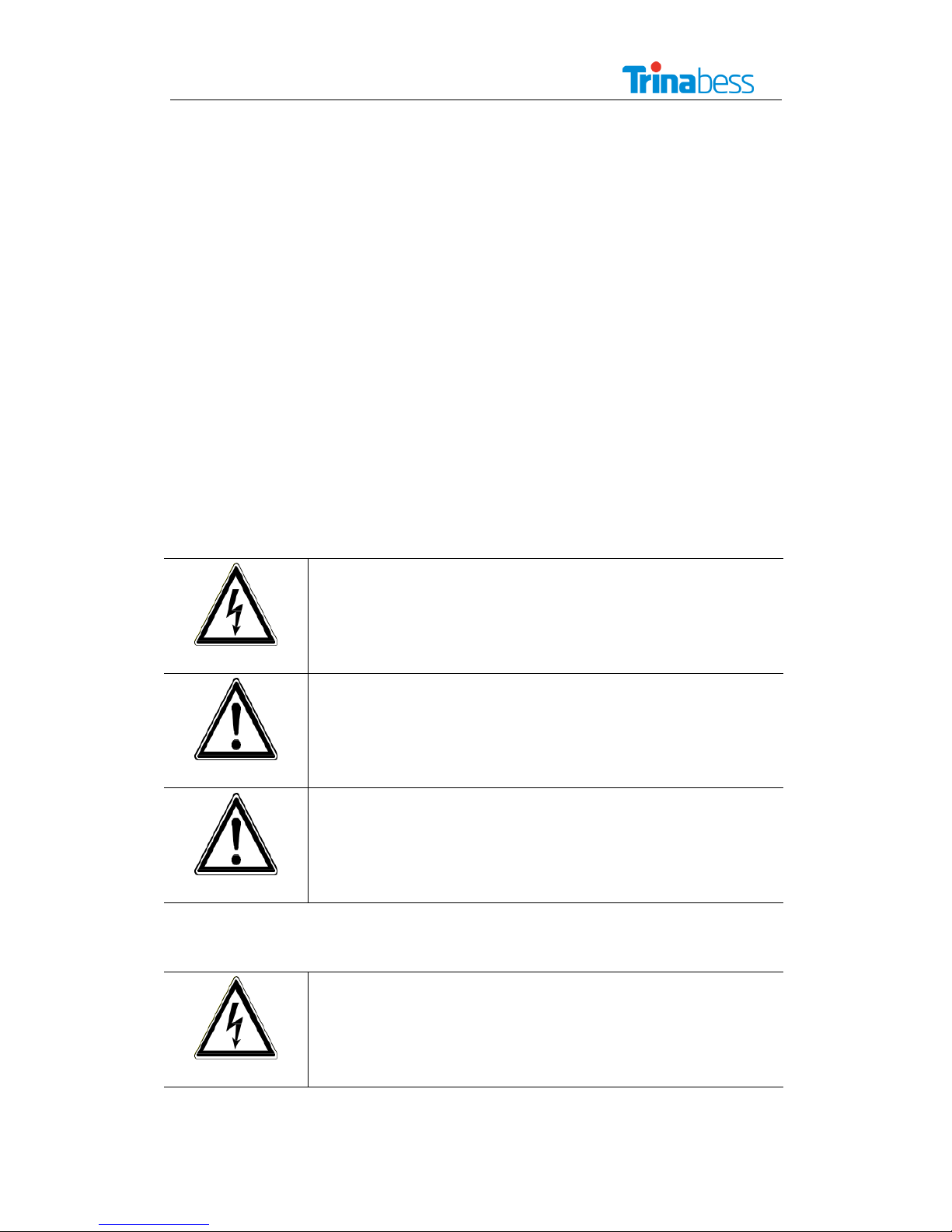
Electric Shock!
Do not open the device! Dangerous voltage may still be applied inside the
device even after it has been switched off.
ELECTRIC SHOCK!
N6052T Solar Battery Hybrid System Installation Manual
2
High leakage current!
Make absolutely sure you have established earthing system before
connecting the device to the supply circuit!
WARNING
Health risk!
Health risk for persons with cardiac pacemakers, metallic implants and
hearing aids in the immediate vicinity of electrical equipment!
WARNING
Risk of improper handling!
Personal injury mechanically by crushing, shearing, cutting or striking.
CAUTION
Cancellation of the operating license!
If the inverter is operated with the wrong country code, the power supply
company may cancel the operating license.
CAUTION
Hot surface!
Surfaces of the housing can be hot! Risk of injury! Risk of burns.
The housing top and the heat sinks may have a surface temperature up to
70°C .
HOT SURFACE!
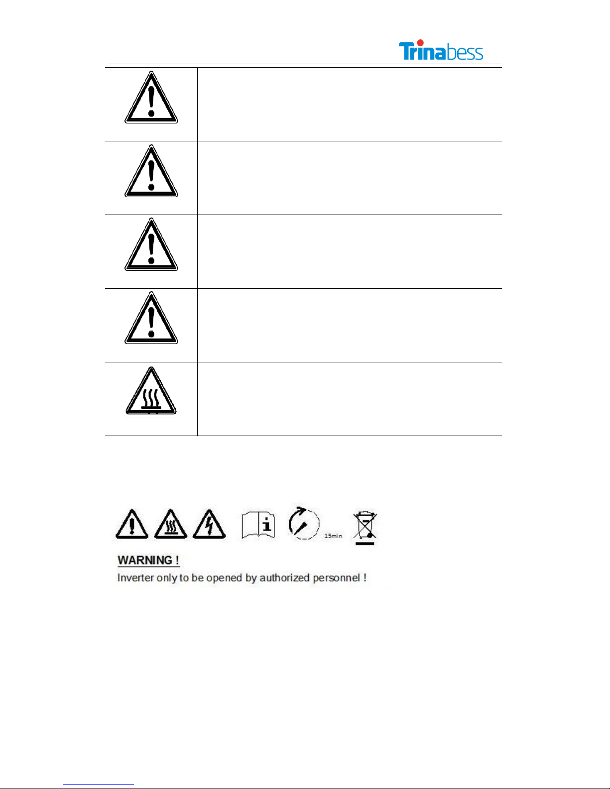
1.3 Warning Notices Affixed to the Device

N6052T Solar Battery Hybrid System Installation Manual
3
1.4 Important Safety Information
The following operating and maintenance instructions must be read before installing, operating or
maintaining the inverter.
Before installation:
Check for damage on the device and package. If you are in doubt, please contact us or the distributor
before installing the device.
Before connecting the solar modules or battery packs with the product, please check the voltages and
make sure they are within the limits of the Trina inverter specifications. Failure to observe these
specifications could void your warranty.
Installation:
Only trained and qualified personnel familiar with local electrical codes may work with the electrical
installations. For optimum safety, please follow the steps described in this manual.
Disconnecting the product:
Please refer to “Disconnecting for maintenance”. Note that, after disconnecting the hybrid inverter
from power grid, PV panels and battery packs, wait at least 15 minutes before the next proceeding.
Operating the product:
Do not commission the device until the whole system complies with the application-specific national
rules and safety regulations.
The ambient conditions given in the product documentation (data sheet) must be observed.
The device manufacturer or installer is responsible for compliance with the limit values as prescribed
in the national regulations.
Only persons who are trained and qualified for the use and operation of this device are allowed to
work on the device.
Maintenance and modification:
Only authorised personnel are allowed to repair or modify the inverter. To ensure optimum safety for
user and environment, only the original spare parts available from your supplier should be used.
Functional safety parameters:
Unauthorised changes of functional safety parameters may cause injury or accidents to people or

N6052T Solar Battery Hybrid System Installation Manual
4
inverter. Additionally it will lead to the cancellation of all inverter operating approval certificates.
1.5 Disposal
Please dispose the package and replaced parts according to the rules applicable
in the country where the device is installed. Do not dispose the inverter with
normal domestic waste.
1.6 Exclusion of Liability
Trina will not be liable for any direct, indirect or consequential damages, losses, costs or losses
including without restriction any economic losses of any kind, any loss or damage to property, any
personal injury, any damage or injury arising from or as a result of misuse or abuse, or the incorrect
installation, integration or operation of the product. We disclaim any liability for direct or indirect
damages due to:
1. Improper installation or commissioning,
2. Modifications, alterations or repair attempts,
3. Inappropriate use or operation,
4. Insufficient ventilation of the device,
5. Non-compliance with relevant safety standards or regulations,
6. Flood, lightning, overvoltage, storm, fire (acts of nature).
We do not assume any liability for an incorrect country code setting.
We reserve the right to make alterations that will improve device function.
N6052T Solar Battery Hybrid System Installation Manual
5
2. Description
2.1 General System Description
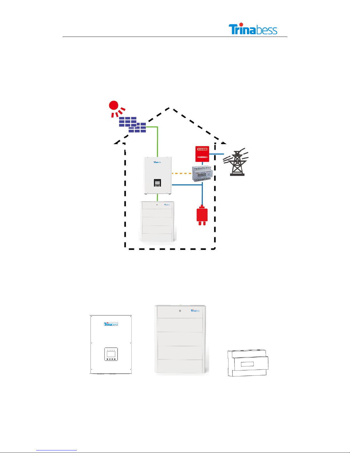
TB5200TH system is a solar battery hybrid system designed for the initial PV installation.
Figure 1 TB5200TH hybrid system
The system includes three main parts: hybrid inverter (with integrated EMS), Li-ion battery packs and
smart meter.
A
B
C
Figure 2 TB5200TH system main parts

N6052T Solar Battery Hybrid System Installation Manual
6
A) TB5200TH hybrid inverter
The TB5200TH hybrid inverter converts the DC power generated by PV modules to AC power. During
the daytime, the PV power will be first used by the household load, then the surplus be charged into
battery packs for later use. Any further surplus PV power will be fed into public grid.
During the nighttime, the TB5200TH hybrid inverter will discharge the battery to supply the load.
B) Battery Packs
Battery packs store the energy generated from the hybrid inverter. Each battery module capacity is 3
kWh, the system capacity is extendable by adding more battery modules; one standard system
consists of two such battery modules.
C) Smart meter
The bi-directional smart meter is used for data collection and communication. With the meter data,
the hybrid inverter decides when to charge/discharge the battery packs.
2.2 System Connection
The three main parts are connected as displayed in Figure3~5, which can optimise solar energy
self-use and realise peak shaving. The user can select the connection mode based on the actual PV
system.
Figure 3 DC Coupling System

N6052T Solar Battery Hybrid System Installation Manual
7
Figure 4 AC Coupling System
Figure 5 DC & AC Coupling System
Note: If the voltage of PV modules exceeds the allowed inverter input voltage value, use the
adapter to reduce the voltage.
Figure 6 Adapter matter

N6052T Solar Battery Hybrid System Installation Manual
8
3. System Installation
3.1 Unpacking the Device
3.1.1 Before Unpacking
All products are thoroughly tested and inspected before they’re packed and transported. Although
they’re shipped in reliable package, damage during transportation could still occur.
It is important to inspect the shipping package prior to the installation carefully. If any external
damage on the package makes you suspect the device could be damaged or if you find that the device
is damaged after unpacking it, please report the damage immediately to your distributor or the goods
forwarder.
If it becomes necessary to return the device, please use the original packages in which they were
delivered.
The gross weight of TB5200TH is 35kg. To avoid injury, take the device by the two holding grips that
are visible on the side and take the device out of the package. Ensure a second person present to
assist in the unpacking and installation of the devices.
3.1.2 Mounting
1. Don’t install the device in direct sunshine. External heating from exposure to the sun may cause
excessive internal heating. This may result in output power being reduced in order to protect the
internal components from damage.
2. The TB5200TH hybrid inverter weights 35kg. The installation wall must be vertical and can carry the
weight of the devices.
3. Install the TB5200TH hybrid in a location where the ambient air temperature is less than 45 ⁰C. The
TB5200TL may reduce its output power if the ambient air temperature exceeds 45 ⁰C (The cooler the
air temperature is, the longer the life expectancy of any electronics device will be).
4. Please refer to the device dimension figure and installation space figure (Figure7~Figure9) to decide
the installation space for TB5200TH and battery cabinet.
5. The system should be installed in a location where is inaccessible to children.
6. The IP class of the inverter is IP65 and the IP class of battery packs is IP 21.
7. It is recommended to mount the device at eye level to ensure optimum user comfort.
8. Do not install the system on flammable construction materials, or in areas close to flammable or
explosive materials.

N6052T Solar Battery Hybrid System Installation Manual
9
Figure 7 TB5200TH hybrid inverter dimension (mm)
Figure 8 Views on battery cabinet

N6052T Solar Battery Hybrid System Installation Manual
10
6kWh
9kWh
12kWh
15kWh
18kWh
Dimensions
(W x H x D)
740 x 600 x
180 mm
740 x 820 x
180 mm
740 x 1040 x
180 mm
740 x 1260 x
180 mm
740 x 1480 x
180 mm
Table 1 Battery cabinet dimension
Figure 9 Installation space (mm)

N6052T Solar Battery Hybrid System Installation Manual
11
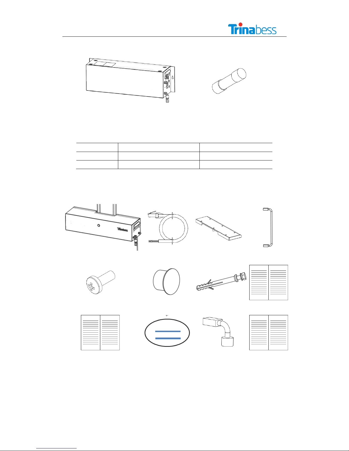
3.1.3 Packing List
3.1.3.1 TB5200TH Hybrid Inverter Packing List
A2
A3
A1
A4
Figure 10 TB5200TH packing list
Item
Description
pcs
A1
TB5200TH hybrid inverter
1
A2
TB5200TH hybrid inverter mounting bracket
1
A3
Aviation Plug Female (for AC grid connection)
1
A4
Expansion tube
6
Table 2 TB5200TH hybrid inverter packing list
3.1.3.2 Battery Packing List
The battery is consisted of battery modules, battery control box and capacity extension accessories,
for different system capacities the scope of supply are also different, as below:
Battery module
Battery control box
Extension
accessories
6kWh
2
1
0
9kWh
3
1
1
12kWh
4
1
2
15kWh
5
1
3
18kWh
6
1
4
Table 3 Different scope of battery supply
N6052T Solar Battery Hybrid System Installation Manual
12
3.1.3.2.1 Battery module packing list
B1
B2
Figure 11 Battery module packing list
Item
Description
PCS
B1
PACK
1
B2
FUSE
1
Table 4 Battery module packing list
3.1.3.2.2 Battery control box packing list
B3
B4
B5
B6
B7
B8
B9
B10
B11
B12
B13
B14
Figure 12 Battery control box packing list

N6052T Solar Battery Hybrid System Installation Manual
13
Item
Description
PCS
B3
Control box
1
B4
Meter communication cable
1
B5
Battery pack communication cable
2
B6
Mounting bracket
2
B7
M4 screw
14 (2 spare parts)
B8
Plug
14 (2 spare parts)
B9
Expansion tube
4
B10
Installation manual
1
B11
User Manual
1
B12
Certificate
1
B13
Resistance
1
B14
Warranty
1
Table 5 Battery control box packing list
3.1.3.2.3 Battery capacity extension accessories:
B13
B14
B15
B16
Figure 13 Capacity extension accessories packing list
Item
Description
PCS
B13
Mounting bracket
2
B14
Battery pack communication cable
1
B15
M4 screw
10 (1 spare part)
B16
Plug
5 (1 spare part)
Table 6 Capacity extension accessories packing list
The standard capacity of TB5200TH hybrid system is 6kWh, be consisted of two 3kWh battery modules,
and the battery capacity is extendable up to 18kWh.

N6052T Solar Battery Hybrid System Installation Manual
14
Item
Dimensions
(W x H x D)
740 x 600 x
180 mm
740 x 820 x
180 mm
740 x 1040 x
180 mm
740 x 1260 x
180 mm
740 x 1480 x
180 mm
Weight
70 kg
100 kg
130 kg
160 kg
190 kg
Number of Energy
Storage Modules
2
3
4
5
6
Usable Battery
Capacity
6 kWh
9 kWh
12kWh
15 kWh
18 kWh
Continuous Battery
Power
- 3 kW
- 4.5 kW
- 6 kW
- 7.5 kW
- 9 kW
Cell Technology
Lithium-ion
Installation Type
Stand-mounted or wall-mounted
Communication
CAN2.0
AC / DC-coupled
Possible(system-dependent)
Single-phase or
Three-phase
Possible(system-dependent)
DOD
100 %
Cycle Life
> 8000
Certificate
IEC 62619,UN 38.3
IP Protection Class
IP 21
Operating
Temperature Range
-10 ~ 45 ℃(- 10 ~ 0 ℃with derating)
Storage Conditions
<1 month
<3 months
<12 months
0~55 ℃
0~45 ℃
0~25 ℃(before storage the SOC will be higher than 50%)
Warranty
10 years battery performance
CAUTION: READ SAFETY AND INSTALLATION INSTRUCTIONS BEFORE USING THE PRODUCT.
Table 7 Different capacity options

N6052T Solar Battery Hybrid System Installation Manual
15
3.1.3.5 Unpacking Smart Meter
Figure 14 Smart meter( Acrel ADL3000-E/C)
3.2 Mounting
Choose a proper location to install the system.
3.2.1 Mounting TB5200TH Inverter
1) Choose a proper position for the mount bracket on the wall and mark it
2) Use Φ10 drill template to drill holes on marked position
3) Fix the expansion bolt into the hole
4) Fix wall bracket on the wall
5) Fix screw through bracket to expansion tube, adjust the bracket position and screw up
6) Align with wall bracket, move TB5200TH in horizontal direction to proper position
7) Make the hook on wall bracket insert into the hole on TB5200TH hybrid inverter
8) Slowly lower TB5200TH, ensure the inverter hang on the hook of wall bracket
9) Check if TB5200TH is properly fixed on the wall
Install demonstration:
Figure 15 Mounting TB5200TH inverter on the wall

N6052T Solar Battery Hybrid System Installation Manual
16
3.2.2 Mounting Battery Packs
For the installation of battery packs, here we take the default TB5200TH hybrid system (6kWh with
2x3 kWh battery modules) as an example. The system with 6kWh battery packs is still to be installed
on the wall. However, considering the bearing capacity of the wall, for system with more than 6kWh
battery, floor-standing installation is recommended.
Mount the battery modules on the wall
1) Drill holes to suit M6 anchor bolts in the wall at the proper position
2) Fix wall bracket on the wall
3) Align the first battery module with the bracket, move the battery module(or control box) in
horizontal direction to proper position
4) Slowly lower the battery module and hang it on the wall bracket
5) Check if battery module(or control box) is properly fixed on the wall
6) Repeat the above 5 steps and install the following battery modules and the battery control
box respectively
Table of contents
Popular Camera Accessories manuals by other brands

Really Right Stuff
Really Right Stuff B150-B user guide

Fantasea
Fantasea FP-5000 manual

Panasonic
Panasonic WV-QCL500-S operating instructions

Nodal Ninja
Nodal Ninja EZ-Leveler II Fanotec Quick reference guide

Minolta
Minolta MAXXUM DYNAX FLASH 3200I - PART 2 instruction manual

Waeco
Waeco BatteryPack BP 124 operating manual


