Trinnov Audio ST2-HIFI User manual


Thank You
for choosing Trinnov Audio.
Your ST2 HiFi: Serial umber: Product ID:


1
7
8
9
1 0
1 1
1 2
1 4
2
INSTALLATION 1 5
2.1 TYPICAL CONNECTIONS
2.2 CONNECTING A SOU CE
2.3 CONNECTING SPEAKE S
2.4 CONNECTING THE MIC OPHONE
1 6
1 7
1 8
1 9
3
GETTING STARTED 20
3.1 POWE ING ON THE ST2-HIFI
3.2 EMOTE ACCESS TO THE G APHICAL USE INTE FACE (GUI)
3.3 USING THE ST2 HIFI AS A WIFI ACCESS POINT
3.4 USING THE ST2 HIFI AS A DHCP CLIENT
3.5 EMOTE ACCESS F OM A TABLET, LAPTOP O SMA TPHONE
3.6 CONNECTING THE ST2 HIFI TO AN EXISTING WIFI NETWO K
22
23
24
25
26
30
5
BASIC O TIMIZER SETU 47
5.1 OVE VIEW
5.2 P ESETS SELECTION & OUTPUT CONNECTIONS
5.3 MIC OPHONE SETUP
5.4 CALIB ATION LEVEL ADJUSTMENT
5.5 C OSSOVE CALIB ATION
5.6 SPEAKE CALIB ATION
5.7 AUTOMATIC P ESETS
49
50
52
54
55
59
62
THE ST2 HIFI
4
CONFIGURATION 33
4.1 OVE VIEW
4.2 SETTING UP THE AUDIO CLOCK
4.3 INPUTS CONFIGU ATION
4.4 P ESETS MANAGEMENT
4.5 POWE -ON DEFAULT SETTINGS
4.6 USB BACKUP ESTO E
4.7 CHANNELS SETTINGS
34
36
37
39
40
41
42
6
ADVANCED O TIMIZER SETU 65
6.1 T INNOV CE TIFIED INSTALLE S
6.2 A BO ESCENCE OF THE ADVANCED SETTINGS MENU
6.3 ITE ATIVE P OCEDU E
6.4 OPTIMIZE G APHS
6.5 OPTIMIZE MODES
6.6 OPTIMIZE SETTINGS
6.7 TA GET CU VE / LIMITE CU VES
6.8 ABOUT LATENCY
66
66
67
69
71
75
77
80
7
MULTI OINT CALIBRATION 81
7.1 P INCIPLE
7.2 MEASU EMENT POSITIONS
7.3 MULTIPOINT ENGINE
82
82
83
8
MULTICHANNEL SETU S 85
8.1 SOU CES CONFIGU ATION
8.2 SOU CES OUTING
8.3 SPEAKE S CONFIGU ATION
8.4 SPEAKE S OUTING
86
87
88
90
1 .1 IMPO TANT SAFETY INST UCTIONS
1 .2 WHAT'S IN YOU BOX
1 .3 CONCEPT
1 .4 THE EA PANEL
1 .5 SPECIFICATIONS
1 .6 3D MEASU EMENT MIC OPHONE


7
1 .1
IM ORTANTS SAFETY INSTRUCTIONS
1 .2
WHAT'S IN YOUR BOX
1 .3
CONCE T
1 .4
THE REAR ANEL
1 .5
S ECIFICATIONS
1 .6
THE 3D TRINNOV MEASUREMENT MICRO HONE
8
9
1 0
1 1
1 2
1 4
8
1 .1
IM ORTANT SAFETY INSTRUCTIONS
2. Follow all warning and instructions.
3. TRI OV Audio expressly forbids unauthorized modification
of this equipment.
4. Using the unit in the following locations can result in a
malfunction:
.
In direct sunlight
.
Locations of extreme temperature or humidity
.
Excessively dusty or dirty locations
.
Locations of excessive vibration
.
Close to magnetic fields
5. Condensation can form on the inside of the apparatus if it is
suddenly moved from a cold environment to a warmer
location. Before switching the unit on, it is recommended
that the unit be allowed to reach room temperature.
6. Clean only with a dry cloth. Do not use liquid solvent-based
cleaners.
7. Do not cover of bloc ventilation slots or openings. ever push
objects ofany kind into ventilation slots on the equipment casing.
This symbol is intended to alert
the user to the presence of
uninsulated "dangerous voltage"
within the product's enclosure
that may be sufficient magni-
tude to constitute a risk of
electric shock to persons.
1 . R ad th following instructions car fully. Sav all instructions for futur r f r nc .
8. Install in conformance with the manufacturer's instructions.
9. Maximum permissible operating conditions: 0°C to 40°C, 20-
65% relative humidity.
1 0. Protect the power chord from being walked on or pinched
particularly at plugs, convenience receptacles, and the point
where they exit from the apparatus.
1 1 . Always replace damaged fuses with the correct rating and type:
3,1 5 AT.
1 2. Unplug this apparatus during lightning storms or when unused
for long periods of time.
1 3. Do not open the equipment case. There are no user serviceable
parts in this equipment. Refer all servicing to qualified
service personnel.
1 4. Please connect the designated AC/AC power supply to an AC
outlet of the correct voltage. Do not connect it to an AC
outlet of voltage other than that for which your unit is
intended.
1 5. TO COMPLETELY DISCONNECT THIS APPARATUS FROM
THE AC MAINS, DISCONNECT THE POWER SUPPLY CORD
PLUG FROM THE AC RECEPTACLE.
This symbol is intended to alert
the user to the presence of impor-
tant operation and maintenance
(servicing) instructions in the litera-
ture accompanying the appliance.

9
THE ST2-HIFI
1 TRINNOV 3D MICROPHONE
1 POWER CABLE
1
2
3
1
2 3
(optional)
1 .2
1 0
The weakest element of any high-fidelity system is the room. Typical rooms introduce up to 1 0dB of distortion
in the frequency response. Furthermore, loudspeakers with a perfect impulse response don’t exist.
Trinnov’s ST2 HiFi solves the acoustic equation. It takes your high-end system to a whole new level of accuracy,
from High-Fidelity to Acoustic-Fidelity.
1 .3
CONCE T

1 1
1 .4
THE REAR ANEL
POWER
SOCKET POWER
SWITCH
T3.1 5
FUSE SERIAL NUMBER
AND MENTIONS RS
232
(unused)
PS/2 ETHERNET
DB25
(unused)
DVI VGA 4XUSB
1 In & 1 Out
AES/EBU
XLR
2 stereo analog
single-ended Inputs
RCA
2 stereo analog balanced
Inputs
XLR
1 In & 1 Out
coaxial SPDIF
RCA
4 analog single-ended
Outputs
RCA
4 analog balanced
Outputs
RCA
ower section Audio section
C section
1 2
1 .5
S ECIFICATIONS
HIGH PERFORMA CE AUDIO
RESOLUTION / SAM LING RATE
A/D SIGNAL-TO-NOISE RATIO
THD+N ADC
D/A SIGNAL-TO-NOISE RATIO
THD+N DAC
CLOCK / JITTER
OWER SU LY
SAFETY COM ONENTS
DESIGN AND ASSEMBLY
24 bits/96 kHz – 1 92kHz ready
1 1 9 dB (A-Weighted)
-1 03 dB
1 1 8 dB (A-Weighted)
-98 dB
Variations over 25ps are recovered, jitter attenuation superior to 50 dB is achieved above 1 00Hz
Independant for audio and processing sections
AntiPop relays on each analog output
All Audio boards designed and manufactured in France by Trinnov Audio
PHYSICAL CHARACTERISTICS
CHASSIS:
2U
POWER SUPPLY:
240V AC / 50-60 Hz.
Option: 1 30V AC
CONSUMPTION:
90 W max.
WEIGHT:
above 9,4kg
ENVIRONNEMENTAL CONDITIONS:
• Temperature: 0°C – 40°C (32°F – 1 04°F)
• Humidity: 20% – 80% relative humidity (without condensation)
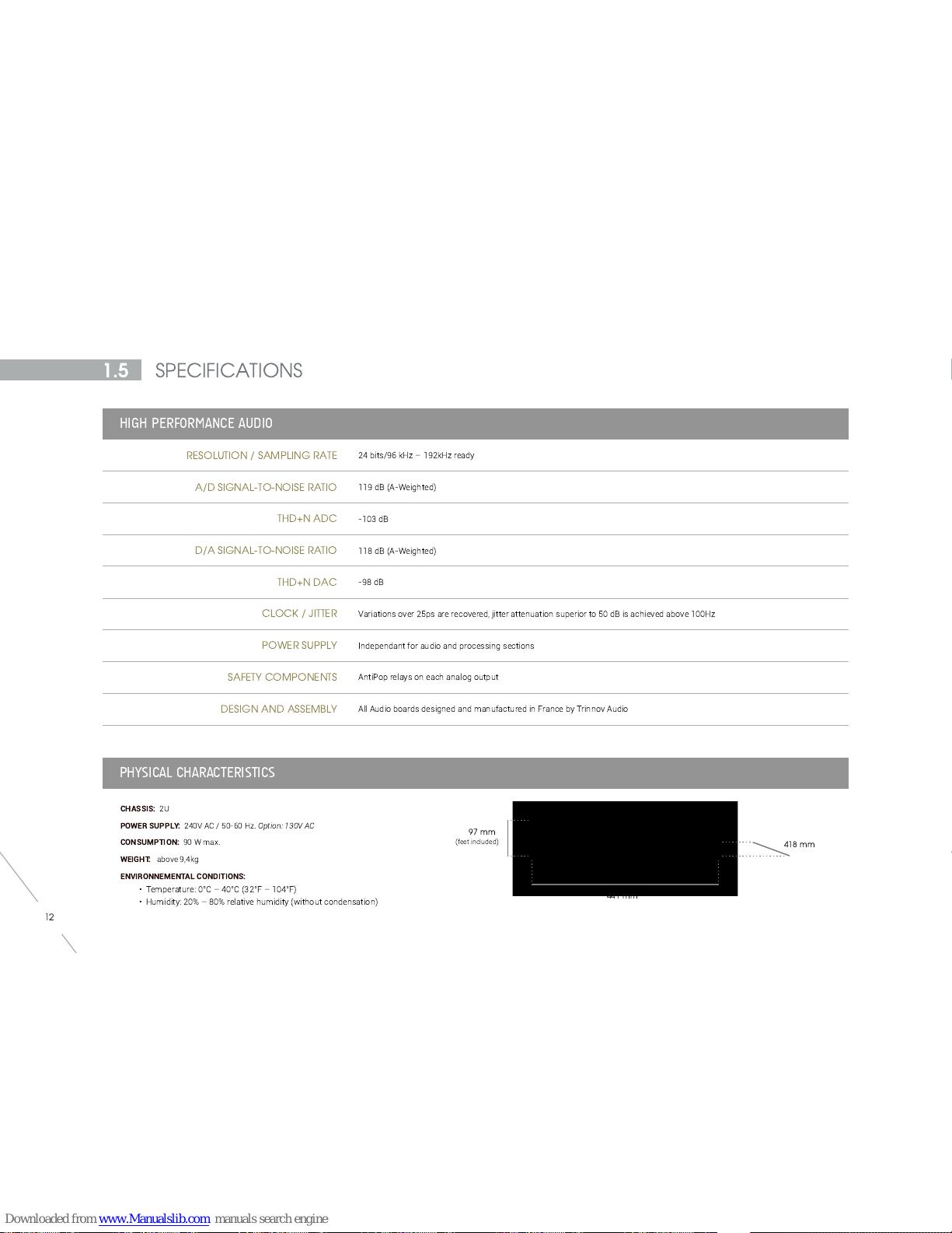
97 mm
(feet included)
41 8 mm
441 mm
1 3
CO ECTIVITY
ANALOG IN UTS/OUT UTS
• 4 single-ended channels inputs via 4 x cinch (1 0k Ohms)
• 4 single-ended channels outputs via 4 x cinch (1 0k Ohms)
• 4 balanced channels inputs via 4 x XLR (20k Ohms)
• 4 balanced channels outputs via 4 x XLR (20k Ohms)
AES IN UTS/OUT UTS
• 2 channels input via 1 x XLR (1 1 0 ohms)
• 2 channels output via 1 x XLR (1 1 0 ohms)
S DIF IN UTS/OUT UTS
• 2 channels inputs via 1 x cinch (75 ohms)
• 2 channels outputs via 1 x cinch (75 ohms)
IMPORTANT NOTE
SPDIF, AES, Single-Ended and Balanced Analog outputs are mirrored.
PROCESSI G SECTIO
ROCESSOR
DATA WIDTH
RAM
STORAGE
COOLING SYSTEM
MAX. NUMBER OF ROCESSING CHANNELS
Intel Dual-Core 1 ,8 GHz
64 bits, floating point
1 Go DDR3
Flash Drive 1 GB
Custom heat sinks + additionnal slow fans
4 channels at 96 kHz

1 4
Switching off
O
Powering on
Back side of the microphone
The measurement microphone is one of the most critical
component in the Trinnov calibration procedure.
The Optimizer’s sophisticated algorithms not only rely on very accurate acoustic measure-
ments but also on the ability to localize speakers positions and to detect early reflection origin.
The microphone consists of 4 capsules mounted at the top of thin brass tubes to avoid
diffraction.
The capsules form a tetrahedron figure, ideal to identify distance, azimuth and elevation
altogether with a spatial resolution below +/-2° in every direction.
Consequently, capsules are identified from 1 to 4 and the microphone cables are labelled
accordingly.
A led incorporated in the body of the microphone indicates the front of the microphone that
should be pointed at the center of the soundstage before proceeding with a measurement.
Flat response (within +/- 0,1 dB across the 20Hz-24kHz frequency range) is guaranteed
by individual compensation filters.
The microphone uses a standard 9V PP3 LR61 battery to power capsules and electronic.
The second purpose of the frond led is to indicate the battery level.
1 4
1 .5
THE TRINNOV 3D MEASUREMENT MICRO HONE
OFF
1
4
23
Front of the microphone
CAMERA STAND
THREAD
MICRO HONE STAND
THREAD (3/8E)
Bottom view
Top view
CA SULES NUMBERING SYSTEM
4
2
3
1

1 5
2.1
TY ICAL CONNECTIONS
2.2
CONNECTING A SOURCE
2.3
CONNECTING S EAKERS
2.4
CONNECTING THE MICRO HONE
1 6
1 7
1 8
1 9
1 6
SOURCES
ST2-HIFI
OWER AM S
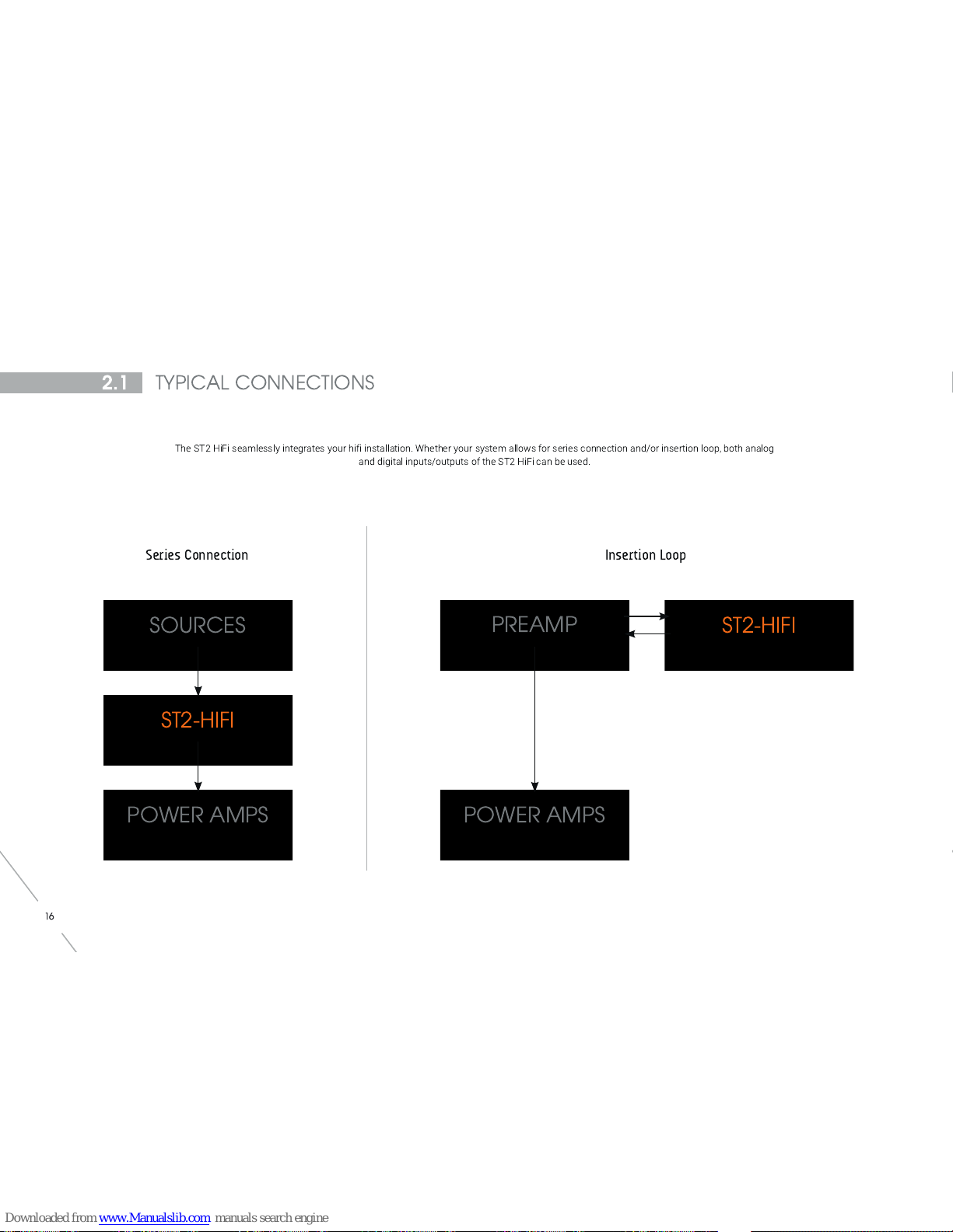
Series Connection
REAM ST2-HIFI
OWER AM S
Insertion Loop
2.1
TY ICAL CONNECTIONS
The ST2 HiFi seamlessly integrates your hifi installation. Whether your system allows for series connection and/or insertion loop, both analog
and digital inputs/outputs of the ST2 HiFi can be used.
1 6

1 7
2.2
CONNECTING A SOURCE
The ST2 HiFi allows you to connect and play any stereo source without any configuration.
This example shows how to connect the AES output from a CD player to the ST2 HiFi.
CD
LAYER
Connecting a CD Player
to the AES Input 1
1 7

1 8
STEREO OWER
AM LIFIER
2.3
CONNECTING S EAKERS
Default output connectors for a stereo system
This image shows that any first pair of outputs should be used as default stereo system output.
Please remind that these outputs play simultaneously.
Stereo System connection example
1 8
1 9
2.4
CONNECTING THE MICRO HONE
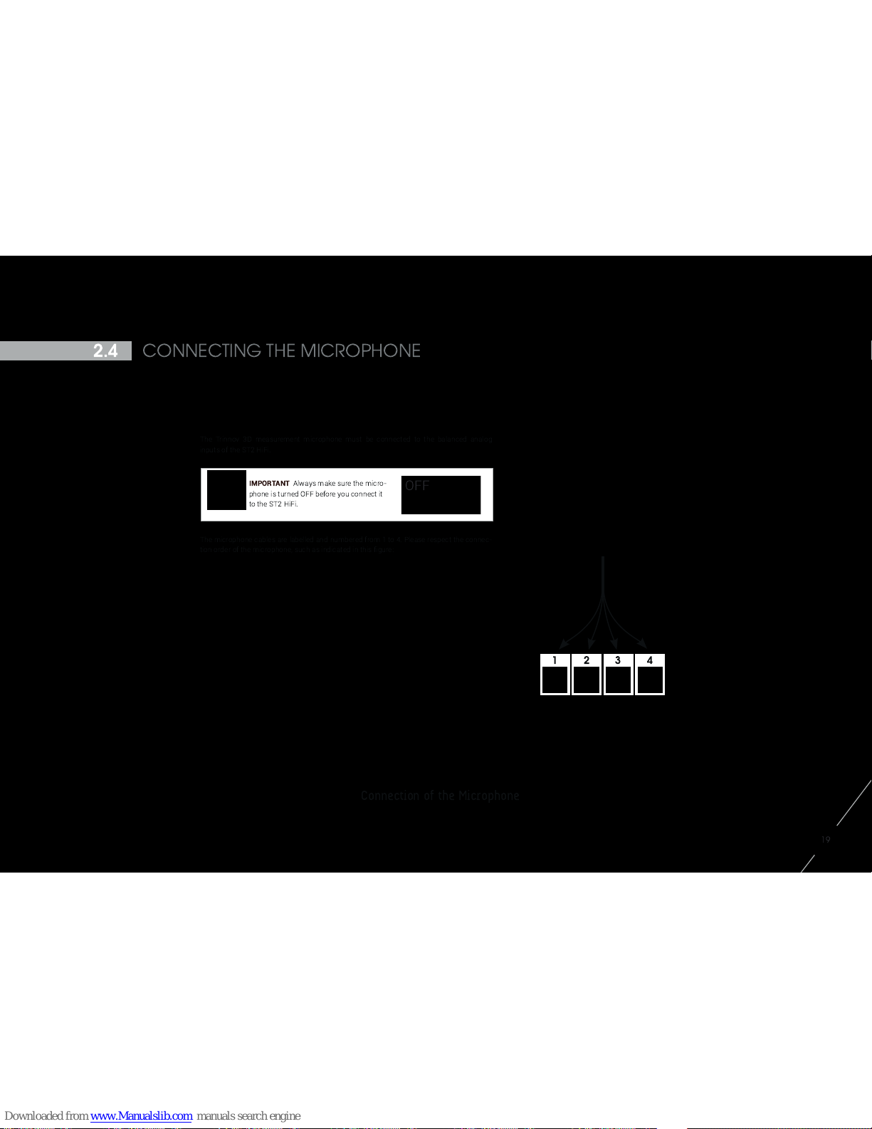
Connection of the Microphone
1 9
12 3 4
IMPORTANT
Always make sure the micro-
phone is turned OFF before you connect it
to the ST2 HiFi.
The Trinnov 3D measurement microphone must be connected to the balanced analog
inputs of the ST2 HiFi.
The microphone cables are labelled and numbered from 1 to 4. Please respect the connec-
tion order of the microphone, such as indicated in this figure:
OFF

Other manuals for ST2-HIFI
1
Table of contents
Other Trinnov Audio Recording Equipment manuals


