Trio CASA VT-150 User manual

IC~RISIRI
~~~h~b~S~e~t~!=n~
5~~~~~!!:o~
WWW.C3S3.CO.nz
Ph:
+64-4-9393
777
eMail:
2
CHANNEL
SOLID
STATE
VOLT
METER
VT-15[]
INSTRUCTION
MANUAL
~TRIO

I
I
I
I
I
I
"
I
I
I
I
I
I
I
I
I
I
I
I
I
I
"I
I
I
I
I
I
I
I
I
I
I
I
I
I
I
I
I
I
I
I
I
I
I
I
I
I
I
I
I
I
I

1.
2.
).
4.
CONTENTS
FEATURES
...........................................
SPECIFICATIONS .....................................
CIRCUIT DESCRIPTION
OPERATING
INSTRUCTIONS
.............................
Page
2
3
5
7
5.
CAUTION
ON
HANDLING
THE
SET
•••••••••••••..••••••.••
12
6.
BLOCK
DIAGRAM,
SCHEMATIC
DIAGRAM
&
DRAWING
OF
EXTERNAL
VIEW
....•••..•.........
13
FEATURES
2~~~~------------------------------------------------
FEATURES
The
model
VT-150
is
a
2-channel
solid-state
voltmeter
with
an
r.m.s.
scale.
It
provides
facilities
to
make
an
accurate
and
stable
voltage
measurement
from
a
minute
voltage
of
1
mV
up
to
300
V
with
'frequencies
of
10
Hz
to
500
kHz.
The
model
VT-150
has
an
extremely
high-sensitivity.
So,
it
may
also
be
used
for
measurement
of
the
noise
of
power
source
and
others,
not
to
speak
of
general
measurements.
Further,
it
may
be
used
as
a
high-gain
amplifier.
FEATURES
**
All
solid-state
circuitry
provides
minimum
warm-up
time
and
small
power
consumption.
**
2-pointer
meter
promises
more
effective
uses
of
a
space
com-
paring
with
those
provided
by
two
sets
of
conventional
voltmeter.
**
Frequency
bandwidth
of
10
Hz
to
500
kHz
and
voltage
range
of
1
mV
to
JOO
V
available
for
various
uses.
**
Metal-film
resistor
with
a
low
temperature
coefficient
and
less
secular
change
employed
as
attenuator
resistor.
**
Voltage
regulator
circuit
provided
in
power
supply
circuit.
**
Voltage
scale
graduated
in
r.m.s.
values
of
sine
wave
voltages,
dB
and
dBm
scales
-
easy
means
provided
specifically
for
measure-
ment
of
S/N
and
so
on.
**
Monitor
output
terminals
provided
for
connection
of
an
oscil-
loscope
and
the
likes.

VOLTMETER
Voltage
range
Accuracy
dB
dBm
Frequency
response
(Reference
of
1kHz)
Input
impedance
Change
due
to
power
Source
voltage
vari-
ation
Temperature
coef-
ficient
Operating
temper-
ature
Rated
Max.
input
voltage
Channel
isolation
SPECIFICATIONS 3
2 SPECIFICATIONS
1mV
full
scale
to
300V
full
scale
in
12
range
(0.001/0.003/0.01/0.03/0.1/0.J/1/3/10
30/100/300)
-80
to
+50 dB
(0
dB
= 1V)
-80
to
+52
dB
(0
dB =
1mW,
6oo
Q)
=3%
of
full
scale
reading
(At
1
kHz)
±10%
from
10Hz
to
500kHz
±
5%
from
20Hz
to
250kHz
=
3%
from
20Hz
to
100kHz
1M
Q
shunted
by
45
PF
or
less
Within
±0.5%
of
full
scale
reading
against
±10%
variation
of
power
source
voltage
DC
component
±400V
AC
component
300Vr.m.s.
for
0.3V
range
or
.:
lower
500Vr.m.s.
for
1V
range
or
higher
80
dB
or
more
(When
each
channel
operated
separately,
with
range
set
at
1V
and
one
of
channels
input
terminal
open)
50
dB
or
more
(When
both
channel
co-operated,
with
range
set
at
1V
and
one
of
channels
input
terminal
open)
MONITOR
OUTPUT
CHARACTERISTIC
Gain
Output
voltage
Approx.
40 dB
:
Approx.
1V

4
SPECIFICATIONS
Frequency
response
Output
impedance
Distortion
facter
S/N
POWER
REQUIREMENT
DIMENSIONS
WEIGHT
ACCESSORIES
Within
:2
dB
from
10Hz
to
500kHz
(Reference
of
1kHz)
Approx.
600Q
1o/o
or
less
at
full
scale
reading
(At
1kHz)
40
dB
or
more
at
full
scale
reading
AC100V,
117V,
2JOV (:10o/o)
50/60Hz
5W
MAX.
W140(144)
x
H200(225)
X
D235(277)mm
Dimensions
in
( )
are
those
which
contain
all
protrusions.
J.?Kg
(7
.lbs)
2
test
leads
(CA-36)
with
a
dual
banana
plug.
2
plugs
with
M
type
binding
post
Two
0.5A
and
0.2A
fuses
One
instruction
manual
CIRCUIT
DESCRIPTION 5
3
CIRCUIT
DESCRIPTION
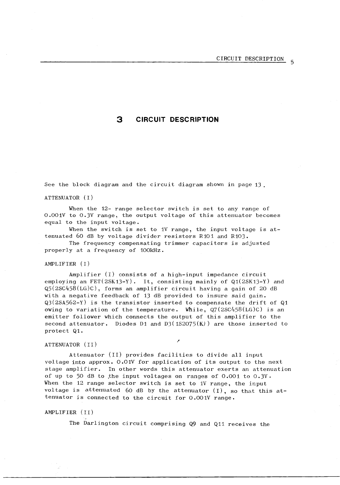
See
the
block
diagram
and
the
circuit
diagram
shown
in
page
13.
ATTENUATOR
(I)
When
the
12-
range
selector
switch
is
set
to
any
range
of
0.001V
to
O.JV
range,
the
output
voltage
of
this
attenuator
becomes
equal
to
the
input
voltage.
When
the
switch
is
set
to
1V
range,
the
input
voltage
is
at-
tenuated
60
dB
by
voltage
divider
resistors
R101
and
R10J.
The
frequency
compensating
trimmer
capacitors
is
adjusted
properly
at
a
frequency
of
100kHz.
AMPLIFIER
(I)
Amplifier
(I)
consists
of
a
high-input
impedance
circuit
employing
an
FET(2SK1J-Y).
It,
consisting
mainly
of
Q1(2SK1J-Y)
and
Q5(2SC458(LG)C),
forms
an
amplifier
circuit
having
a
gain
of
20
dB
with
a
negative
feedback
of
13
dB
provided
to
insure
said
gain.
QJ(2SA562-Y)
is
the
transistor
inserted
to
compensate
the
drift
of
Q1
owing
to
variation
of
the
temperature.
While,
Q7(2SC458(LG)C)
is
an
emitter
follower
which
connects
the
output
of
this
amplifier
to
the
second
attenuator.
Diodes
D1
and
DJ(1S2075{K))
are
those
inserted
to
protect
Q1.
ATTENUATOR
(
II)
Attenuator
(II)
provides
facilities
to
divide
all
input
voltage
into
approx.
0.01V
for
application
of
its
output
to
the
next
stage
amplifier.
In
other
words
this
attenuator
exerts
an
attenuation
of
up
to
50
dB
to
the
input
voltages
on
ranges
of
0.001
to
O.JV.
When
the
12
range
selector
switch
is
set
to
1V
range,
the
input
voltage
is
attenuated
60
dB
by
the
attenuator
(I),
so
that
this
at-
tenuator
is
connected
to
the
circuit
for
0.001V
range.
AMPLIFIER
(II)
The
Darlington
circuit
comprising
Q9
and
Q11
receives
the
6
CIRCUIT
DESCRIPTION
output
of
attenuator
(II)
with
a
high
impedance
and
delivers
its
out-
put
through
transistor
Q11
serving
as
an
emitter
follower
with
a
low
output
impedance
to
the
next
amplifier
stage.
This
amplifier
provides
a
gain
of
approx.J8
dB
at
1kHz
with
a
negative
feedback
of
about
22
dB
provided
to
insure
said
gain.
The
amplifier,
operating
in
combination
with
amplifier
(I),
forms
an
amplifier
circuit
providing
an
overall
gain
of
58
dB
and
an
overall
negative
feedback
of
35
dB.
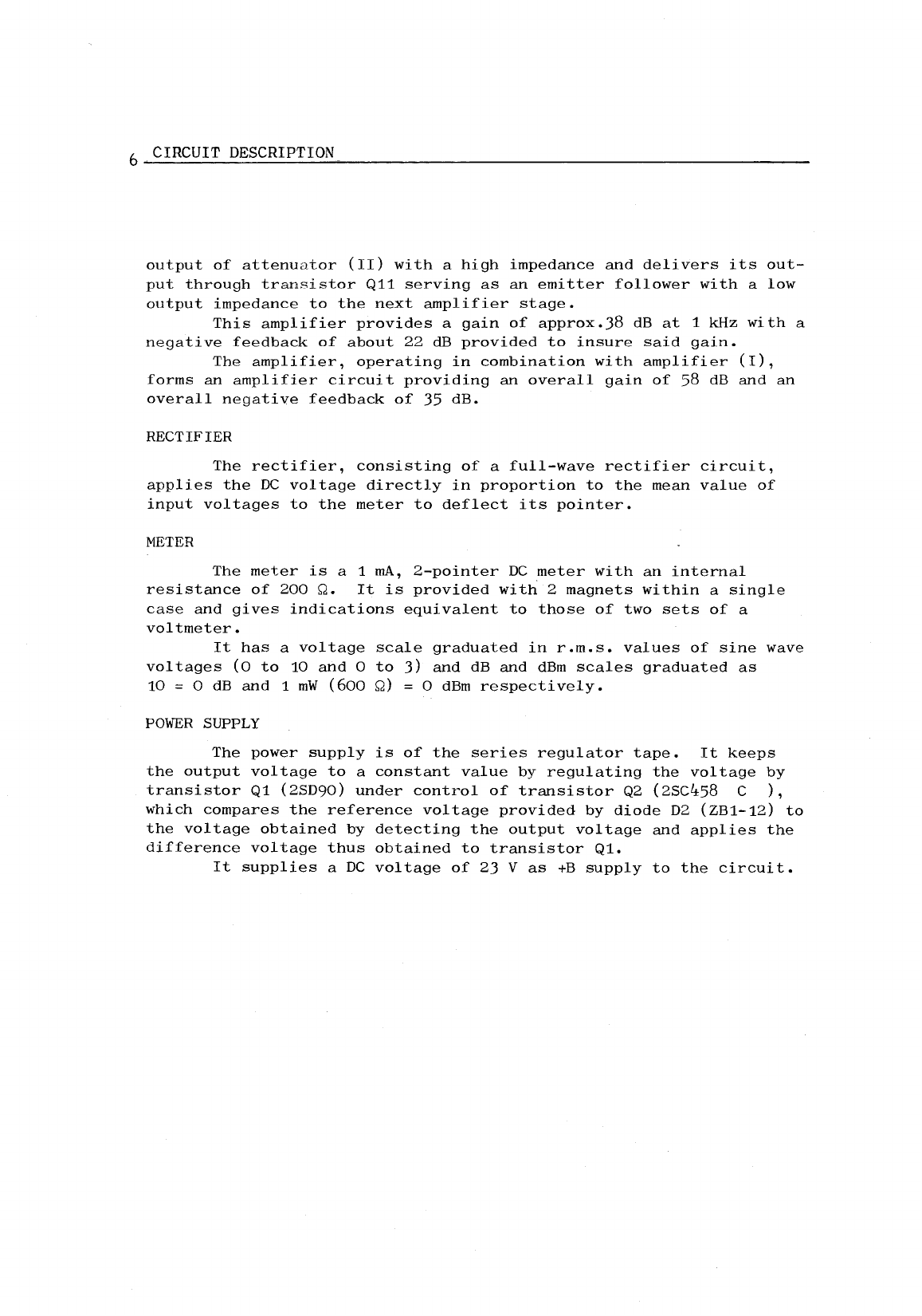
RECTIFIER
The
rectifier,
consisting
of
a
full-wave
rectifier
circuit,
applies
the
DC
voltage
directly
in
proportion
to
the
mean
value
of
input
voltages
to
the
meter
to
deflect
its
pointer.
METER
The
meter
is
a 1
rnA,
2-pointer
DC
meter
with
an
internal
resistance
of
200
Q.
It
is
provided
with
2
magnets
within
a
single
case
and
gives
indications
equivalent
to
those
of
two
sets
of
a
voltmeter.
It
has
a
voltage
scale
graduated
in
r.m.s.
values
of
sine
wave
voltages
(0
to
10
and
0
to
J)
and
dB
and
dBm
scales
graduated
as
10
= 0
dB
and
1
mW
(600
Q) = 0
dBm
respectively.
POWER
SUPPLY
The
power
supply
is
of
the
series
regulator
tape.
It
keeps
the
output
voltage
to
a
constant
value
by
regulating
the
voltage
by
transistor
Q1
(2SD90)
under
control
of
transistor
Q2
(2SC~58
C
),
which
compares
the
reference
voltage
provided
by
diode
D2
(ZB1-12)
to
the
voltage
obtained
by
detecting
the
output
voltage
and
applies
the
difference
voltage
thus
obtained
to
transistor
Q1.
It
supplies
a
DC
voltage
of
23
V
as
+B
supply
to
the
circuit.

OPERATING INSTRUCTIONS 7
4 OPERATING
INSTRUCTIONS
1.
OPERATING
OF
CONTROLS
ON
THE
PANEL
This
voltmeter
is
provided
with
the
controls
on
the
pe1nel
shown
in
the
table
below
and
external
view.
REF.
NO.
MARKING
ON
PANEL DESCRIPTION
(
1)
(NEON
LAMP)
Neon
lamp
which
lights
when
POWER
;:,",witch
is
turned
to
ON.
(2)
POWER
Power
ON-OFF
switch
Throwing
this
switch
in
the
upper
position
turns
on
the
set.
(3)
CH
1 & 2
Attenuator
having
12
positions
to
provide
an
attenuation
to
the
input
voltage
in
10
dB
step.
It
serves
as
the
voltage
range
selector
switch
for
CH1
and
CH2,
when
the
voltmeter
is
set
for
operating
CH1
and
CH2
co-operated.
(4)
CH
2
Attenuator
having
12
positions
to
provide
an
attenuation
to
the
input
voltage
in
10
dB
step.
It
serves
as
the
voltage
range
selector
switch
for
CH2.
(5)
INPUT 1
CHi
input
terminal
(6)
INPUT 2
CH2
input
terminal
·--····~····
"'
..
<
(
7)
GND
Grounding
terminal
(8)
GND
Grounding
terminal

S OPERATING INSTRUCTIONS
REF.
NO.
MARKING
ON
PANEL DESCRIPTION
(9)
CH
2 SELECTOR
In
the
right-
hand
position
of
this
switch
it
allows
the
CH2
attenuator
(4)
to
select
a
voltage
range
for
channel
2.
In
the
left-hand
position,
the
switch
causes
the
set
t_o
operate
CH1
and
CH2
simultaneously
and
allows
the
CH1 & 2
attenuator
(J)
to
select
a
voltage
range
for
both
CH1
and
CH2.
(
10)
Mechanical
zero
adjustment
for
the
pointer
provided
for
channel
CHi.
(
11)
Mechanical
zero
adjustment
for
the
pointer
provided
for
channel
CH2.
(
12)
CH
1
OUTPUT
Monitor
output
terminal
which
provided
for
connecting
CH1
signal
under
measurement
to
an
oscilloscope
and
others
to
observe
the
waveform.
(
13)
CH
2
OUTPUT
Monitor
output
terminal
which
provided
to
observe
CH2
signal
in
the
same
manner
as
CH1 OUTPUT.
(
14)
Power
source
selector
switch
for
AC
100,
117
or
230
v,
50
or
60
Hz.
(.15)
Fuse
(
16)
Power
cord
OPERATING INSTRUCTIONS
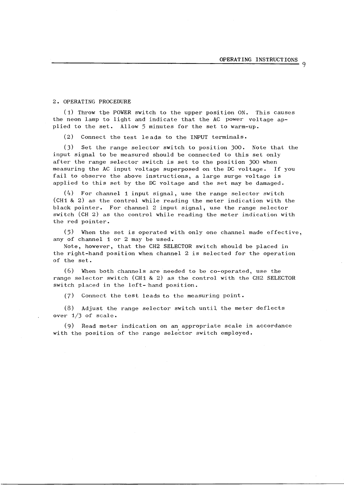
2.
OPERATING
PROCEDURE
(1)
Throw
tbe
POWER
switch
to
the
upper
position
ON.
This
causes
the
neon
lamp
to
light
and
indicate
that
the
AC
power
voltage
ap-
plied
to
the
set.
Allow
5
minutes
for
the
set
to
warm-up.
(
2)
Connect
the
test
leads
to
the
INPUT
terminals.
(J)
Set
the
range
selector
switch
to
position
300.
Note
that
the
input
signal
to
be
measured
should
be
connected
to
this
set
only
after
the
range
selector
switch
is
set
to
the
position
300
when
measuring
the
AC
input
voltage
superposed
on
the
DC
voltage.
If
you
fail
to
observe
the
above
instructions,
a
large
surge
voltage
is
applied
to
this
set
by
the
DC
voltage
and
the
set
may
be
damaged.
(4)
For
channel
1
input
signal,
use
the
range
selector
switch
(CH1 &
2)
as
the
control
while
reading
the
meter
indication
with
the
black
pointer.
For
channel
2
input
signal,
use
the
range
selector
switch
(CH
2)
as
the
control
while
reading
the
meter
indication
with
the
red
pointer.
(5)
When
the
set
is
operated
with
only
one
channel
made
effective,
any
of
channel
1
or
2 may
be
used.
Note,
however,
that
the
CH2
SELECTOR
switch
should
be
placed
in
the
right-hand
position
when
channel
2
is
selected
for
the
operation
of
the
set.
(6)
When
both
channels
are
needed
to
be
co-operated,
use
the
range
selector
switch
(CH1 &
2)
as
the
control
with
the
CH2
SELECTOR
switch
placed
in
the
left-'hand
position.
(7)
Connect
the
test
leads
to
the
measuring
point.
(8)
Adjust
the
range
selector
switch
until
the
meter
deflects
over
1/3
of
scale.
(9)
Read
meter
indication
on
an
appropriate
scale
in
accordance
with
the
position
of
the
range
selector
switch
employed.
9

lO
OPERATING INSTRUCTIONS
3.
READING
METER
INDICATION
Refer
to
the
scales
shown
below.
(1)
VOLTAGE
SCALE
5
VOLTS
DECIBELS
OdBm =1mW600!1
The
voltage
scale
is
the
black
scale
calibrated
doubly
over
ranges
(A)
0 -
10
and
(B)
0 - 3
with
the
black
graduations
and
figures.
When
the
range
selector
switch
is
set
at
position
1 V,
full
scale
graduation
10
of
scale
(A)
1-
10
corresponds
to
1
V.
If
the
switch
is
in
position
300
mV,
full
scale
graduation
3
of
scale
(B)
1
- 3
corresponds
to
300
mV.
The
above
also
applies
to
other
ranges
of
the
meter.
In
other
words,
the
setting
of
the
range
selector
switch
always
coin-
sides
with
the
full
scale
graduation
of
meter
scale
whose
range
corresponds
to
the
selector
switch.
The
reason
why
the
meter
is
provided
with
two
scales
having
an
overlap
range
is
to
supplement
scale
(A)
0 -
10,
which
may
offer
some
difficulties
to
you
when
reading
the
graduations
of
le.ss
than
3,
with
scale
(B)
0 - 3
which
is
an
enlarged
scale
corresponding
to
the
range
of
scale
(A)
from
0
to
3.
Therefore,
read
meter
indication
finely
on
scale
(B)
0 - 3
with
the
range
selector
switch
turned
to
the
next
higher
range
when
the
meter
indication
reads
on
scale
(A)
0 -
10
falls
below
3.
(2)
dB
SCALE
The
dB
scale
is
calibrated
over
a
range
of
-20
to
0
with
the
read
graduations
and
figures,
of
which
a
voltage
ratio
of
0 dB
is
corresponding
to
graduation
10
of
scale
(A).
The
range
selector
switch
has
12
ranges
in
10
dB
step,
so
that
it
provides
an
attenuation
ratio
of
110
dB
over
an
entire
ranges
from
range
1
mV
to
range
300
V.
So,
suppose.
that
the
reference
(0
dB)
equals
1
Von
the
scale
(A),
a
meter
indication
provides

OPERATING
INSTRUCTIONSll
readings
down
to
-60
dB
(1
mV)
through
switching
of
voltage
range
and
also
further
down
to
-20
dB
by
this
dB
scale.
Thus,
it
follows
that
the
meter
provides
facilities
to
continuously
measure
a
voltage
ratio
(1
V -
0.1
mV)
down
to
-80
dB.
For
larger
voltage
than
1 V,
the
meter
indication
provides
facilities
to
measure
a
voltage
ratio
(1
V-
300
V)
up
to
+50
dB.
(3)
dBm
SCALE
In
general,
an
average-responding
voltmeter
has
a
scale
calibrated
with
respect
to
the
reference
level
(i.e.
0 dB)
which
cor-
responds
to
a
voltage
of
0.775
V
generated
across
a
600
Q
resistance
load
(o~
a
power
of
1 mW).
For
this
reason,
the
power
level
of
the
circuit
under
measurement
to
the
reference
level
can
be
measured
through
the
use
of
this
dBm
scale,
provided
that
the
circuit
provides
an
impedance
of
pure
resistance
of
600
Q.
lZ
CAUTION
ON
HANDLING
THE
SET
S CAUTION
ON
HANDLING THE
SET
(1)
In
order
to
make
specifically
accurate
measurement,
allow
about
5
minutes
after
switching
on
for
the
set
to
warm
up.
(2)
Refrain
from
installing
this
set
in
a
place
where
extremely
heavy
magnetic
or
electric
field
prevails.
(J)
In
case
leads
other
than
test
leads
the
supplied
with
the
set
.is
to
be
used
as
the
input
lead,
use
a
lead
having
a
small
inter-
conductor
capacitance
between
the
shielding
and
conductors.
(4)
This
set
is
a
high
sensitivity
voltmeter.
So,
operate
the
set
with
sufficient
care
paid
for
prevention
of
the
noise
of
power
source
and
other
minute
noise.
(
5)
Do
not
leave
the
set
for
many
hours
ln
a
place
where
a
high
temperature
or
humidity
prevails.
(6)
This
set
is
provided
with
one
0.5A
(250
V)
and
0.2A
(250
V)
fuses.
Use
the'0.5A
(250
V)
fuse
when
the
set
is
to
be
operated
from
a
100
or
117
V AC.
For
the
AC
230
V
operation,
use
the
0.2A
(250
V)
fuse.
I
I I
I
lCH1812l
--------
I
I
I
1:~1111
\if'O-ts
'Y\J._,VO~"
~
;!
}~
Qg-
1
s.t9,zo
2SC458(t)
-
2r-v'2n...J'\
0
"
!j
Ju
:n,
-I
Ill
II
fJ'LJ
-~~
I~"
liTil'l.LY'
ro
lCH2
SELECTOR!
t!
POsitions of
S103a--d
are.
set for operation
of
CH1
r--------
7-
and
CH2
separately with 1 I
GH2
SELECTOR
in
the
/ I /
nght SI03Q /
SI03b
/
~
!
Q.l
n
~
~
,rs
~I
I
-~~:~~~7-~-~~~:d-1~7
CI08
330P
CliO
180P
Cll2
47P
R105,
106
6.84KO
Rl07,106
2.6 K0
RI09,110
6840
Rlll,ll22160
Rll3,ll4
68.40
Rll5,116
31.60
X68-IOOO-
00
r----------------,
I
32V
OI2SD90
Q
2
2SC4
58
~3V
I
~
""
Q
J,_j
~
.,
fC2
.I
600WV
Fi~
I 112J
""
@r
N Ul
" "
a:
<D
a:
R23
3.9K
R24 3.9K
D
1-4
182075@
05-8
IN60
I
~rw~~21
lOW
VI
I
I
l~--1
116wv
"'~-
L1Y~+w~n7+;
~
a:
,.
~
R83
2.2K
R84
2.2K
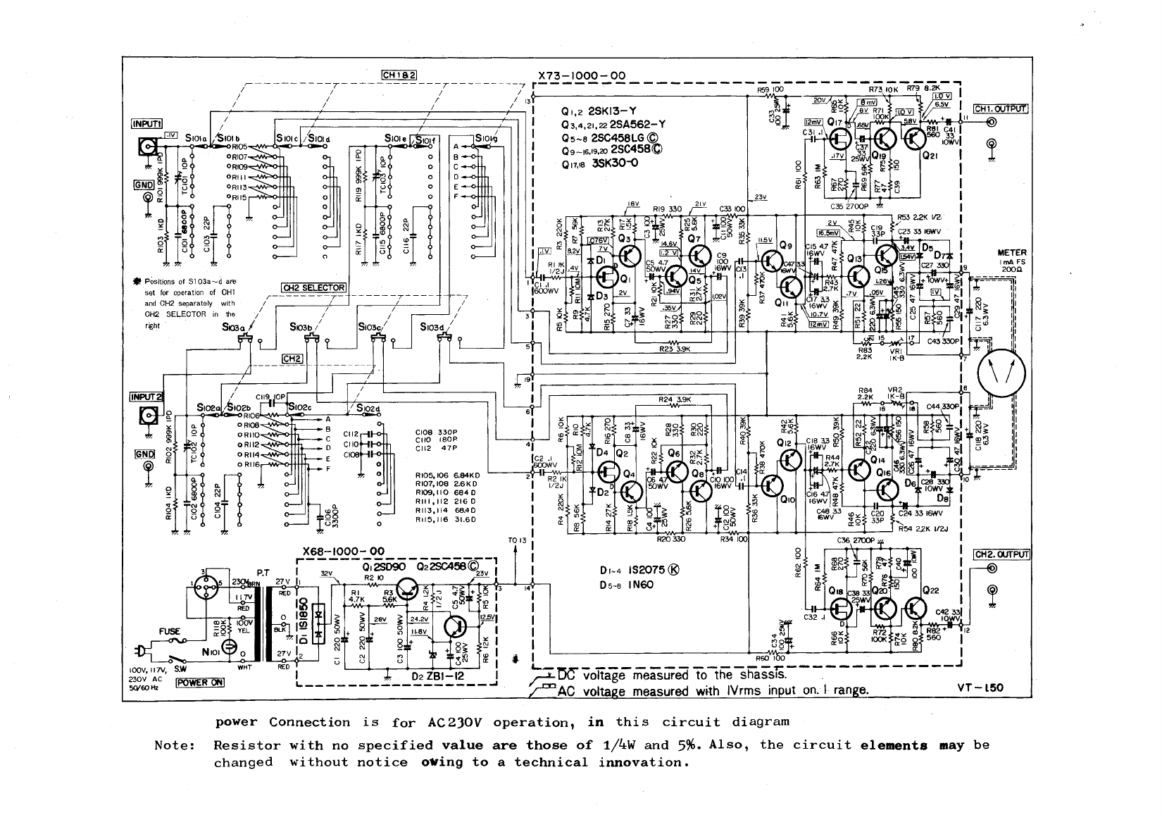
power
Connection
is
for
AC230V
operation,
in
this
circuit
diagram
~
Note:
Resistor
with
no
specified
value
are
those
of
1/4W
and
5%.
Also,
the
circuit
elements
may
be
changed
without
notice
o•ing
to
a
technical
innovation.
METER

Q)
.....,
0
z
BLOCK
DIAGRAM
of
VT-150
CH2
SELECTOR
------7----------,
I
I
I
,----
*
liWH2
SELECTOR
sw<tch
is positioned
for operation
of
CH
and
CH2 separately
I
I I
I I
6 6
100V,
117V
230V
AC
50/60Hz
CH1

A
product
of
TRIO-KENWOOD
CORPORATION
6-ll
3-chome. Aobadai. Meguro'ku. Tokyo153, Japan
@·6448
PRINTED
IN
JAPAN
BS0-0697-00
(KO)
~
Table of contents
Other Trio Measuring Instrument manuals


Popular Measuring Instrument manuals by other brands


Teledyne Lecroy
Teledyne Lecroy PCI Express 2.0 Mid-Bus Probe Installation and usage manual

Chauvin Arnoux
Chauvin Arnoux PAC 20 user manual

Endress+Hauser
Endress+Hauser Micropilot M FMR250 manual

Brymen
Brymen BM157s user manual

Azbil
Azbil 700 series user manual

YASKAWA
YASKAWA 1000 Series installation manual


 Original instruction")


