Trio PS-510 User manual
OPERATINGMANUAL
TRIO
PS-510
POWERSUPPLY
and
SPEAKERUNIT
SPECIAL
FEATURES
CIRCUIT
DESCRIPTION
1.
Designed
jj*n
A.C.powersupplyunitv%-
i-l
i••»•-!v
l.ir
'In-
-
Iir-.
I-I-.IT
1
V
i :i.
(:W
i-i Hi
II
.11.
ili_.it
PI
,|.j.i.vi:i
i:
iiiLi
i|rcC.
3Providedwith
ipa«r
supplycor
J
fin
connec-
i
:•ir•..! Ii
•
It.-I r II
••
>•.--.
1.
AC
p.:»v:i
•
•viccl'
is
Attached
tothe
i
r.ir
*-IVI--,
providing
»
yrt->
I
iiiiivviiiKiiii1
In
tltcopci-i;
i
When
fin
ip*c«
is
*v»iLblc,
the
I'j
I'-r
r
n
b«:
p
jeed
'.Trier
th.;n - .-n wli: i
I
I
.
I
i
..II
....-.'.. •
!:•
l:
.1
..I'..-.
I.
5,F.if.iliic,i vi
ih.ijji-
I.I
rri'r
I,-.il--ii-n-iI I.:r.
..r
i
in
use.
Mild
the
uniquedesigncl
the
srabilhed
|M-i»v-
"i|>|i'v
tymw
:iw»in*k
grvairr
xi.iiiiiit>.
'j.
Specialdesign
->••]•.
r,•nor^ivrn
vj i- to
ITiklill
IIn-' SjiI I : i
DM
I:I
.Cl.
ACLINE
Th«
AC
lin<
oi th<
pOWtT
I
r»n
*l
::-n;irm.iiy
winding
employsfilters
oi
th>e
n
type,thetefcy
pr»
Tenting
the
possibleemission
o(
unili-'in:;l
i lit;
trii
wivv
It:IIIhe
p.iwr
s.ii|l>I lie.
MX
I
VOLI
MM
For
the
800-vidc
current,
M
silicon
roll
ije
doublet
rectifiei
circuit
is
used.
To
withrti*."!
tlw
pc»L-
i-||.'iTO-
i : I -.
n:
r.il-.
in. •
In.Mil
:
'.A ICI
*
in
pBITf
.II
u
placedin
Kcifif.
Resistors
of
highmagnitude,
iii,i-.,.,I
in
pi-ilU-l
toI'M
•ll.iill
ri-illli::i
mi-,
chemical
LiMidcnaei,seive
to
*votd
un
overload
re-
sultingtrcnt
the
imbaJinceof
voltlgM
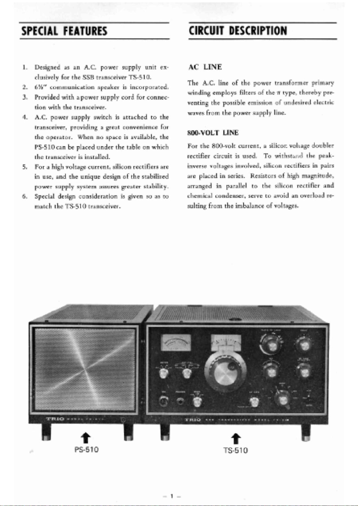
PS-510
-S-D10
i
CIRCUIT
DESCRIPTION
300-VOLT
LINE
To
minimizevariationsandrippleinthe
line,
a
silicon
bridgerectifier
circuit
andchalkinput
system
areemployedforthe300-voltB
line.
210-VOLT
LINE
Resistors
areplacedinseriesbetweenthe300-volt
line
andthe210-voltlineforthepurposeof
droppingthevoltage.
150-VOLT
LINE
If
the150-voltlinevoltagedropsduetoa
varia-
tion
ofload,thegridvoltageonthetriodsideof
V2oi
6BM8
will
alsodrop.
This
causestheplate
currenttodecrease,sincethecathodvoltageis
fixed.
When
theplatecurrentdecreases,thevoltage
drop
acrosstheR201470Kftbecomesless,
while
the
platevoltage
tends
torise.Accordingly,thegrid
biasonthe
pentode
sideof
6BM8
tends
tode-
crease,therebystabilizingthe150-volt
output
at
theoperatingpoint.
This
output
voltagecanbe
varied
byadjustingthe
VRi
half-fixed
resistor.
(-)
C LINE
FOR
BIAS
The
half-wavecurrentissuppliedtothe(-)C line
for
thebiasthrougha
silicon
diode.
12.6-VOLT
LINE
To
supplyheatervoltages,thepowertransformer
hastwo12.6-voltsecondarywindings;
that
is,
one
for
the
final
S2001
x 2 line
exclusively
forthe
transceiver
andtheotherforothervacuumtubes.
Taking
intoconsiderationa possiblevoltage
drop
atthepowersupplycordbetweenthePS-510and
the
TS-510,
thetransformerisprovided
with
two
13.5-volt
windings.
63-VOLT
LINE
A
6.3-voltwindingisusedforheatingthe
6BM8.
To
preventthebreakageoftheinsulationbetween
the
cathode
heaters,thiswindingisapplied
with
a
voltageof+150V.
SPEAKER
TERMINALS
The
powersupply
jack
incorporatesspeakerline
terminals.
Theon-offpower
switch
isattachedto
thetransceiver.Partofthelead
wire
tothetrans-
formerprimarywindingisconnected
with
the
powersupplysocket.
This
enablestheoperatorto
turnonoroffthemachinefromthetransceiver
side.
-
2 -
OPERATING
MAINTENANCE
1.
Accessories
The
PS-510isfurnished
with
thefollowingac-
cessories.
Power
supplyconnectingcord- 2m 1
(with
plugand
jack)
Hyzex
legs2
Fuse
(8A)1
OperationManual1
2.
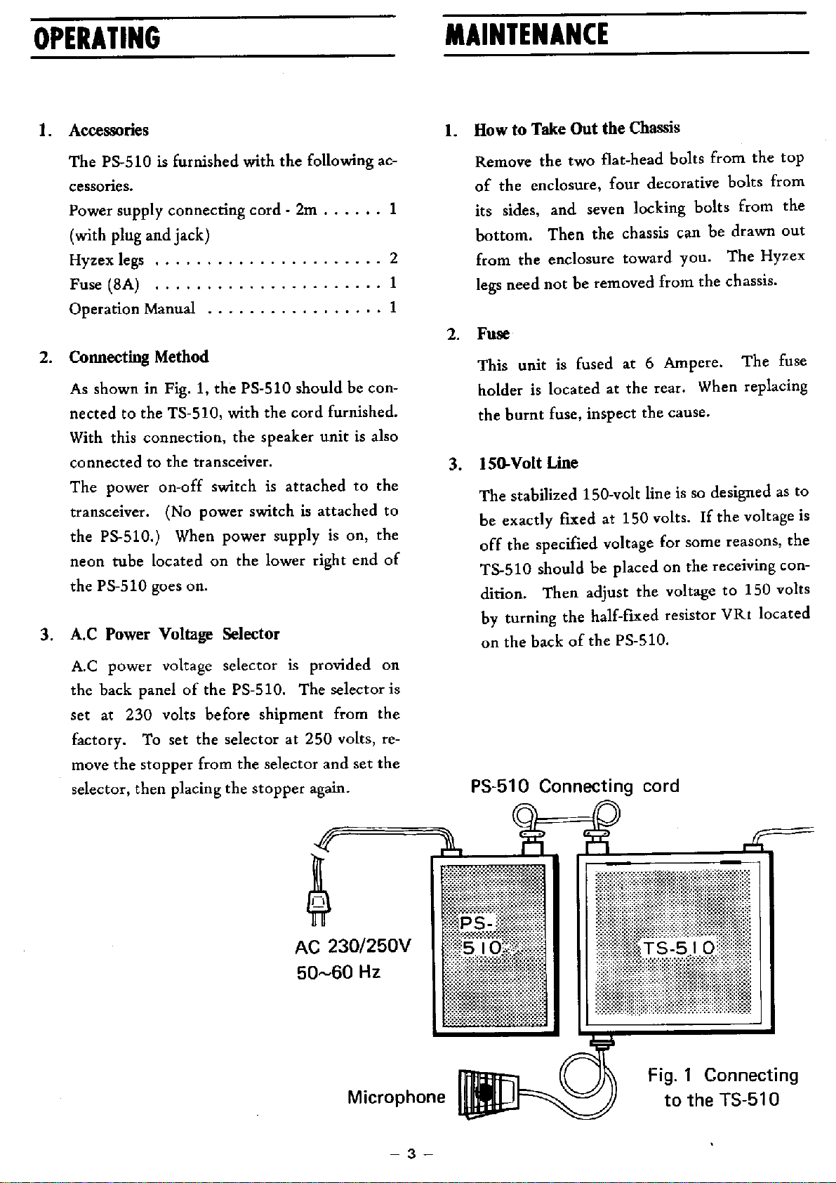
ConnectingMethod
As
showninFig.1,thePS-510shouldbecon-
nectedtothe
TS-510,
with
thecordfurnished.
With
thisconnection,thespeakerunitisalso
connectedtothetransceiver.
The
poweron-off
switch
isattachedtothe
transceiver.
(Nopower
switch
isattachedto
the
PS-510.)
Whenpowersupplyison,the
neon
tube
locatedonthelowerrightendof
the
PS-510
goes
on.
3.
A.CPowerVoltageSelector
A.C
powervoltageselectorisprovidedon
thebackpanelofthe
PS-510.
Theselectoris
setat230voltsbeforeshipmentfromthe
factory.
Tosettheselectorat250volts,re-
movethe
stopper
fromtheselectorandsetthe
selector,thenplacingthe
stopper
again.
AC
230/250V
50-60
Hz
1.
Howto
Take
Outthe
Chassis
Remove
thetwoflat-head boltsfromthetop
of
theenclosure,fourdecorativeboltsfrom
its
sides,andsevenlockingboltsfromthe
bottom.
Then
thechassiscanbedrawnout
from
theenclosuretowardyou.The
Hyzex
legs
neednotberemovedfromthechassis.
2.
Fuse
This
unitisfusedat6 Ampere.Thefuse
holderislocatedattherear.Whenreplacing
theburntfuse,inspectthecause.
3.
150-Volt
Line
The
stabilized150-voltlineissodesignedasto
beexactly
fixed
at150volts.Ifthevoltageis
off
thespecifiedvoltageforsomereasons,the
TS-510
shouldbeplacedonthereceivingcon-
dition.
Then
adjustthevoltageto150volts
by
turningthe
half-fixed
resistor
VRi
located
onthebackofthe
PS-510.
PS-510
Connecting
cord
Microphone
Fig.
1
Connecting
to
the
TS-510
-
3 -
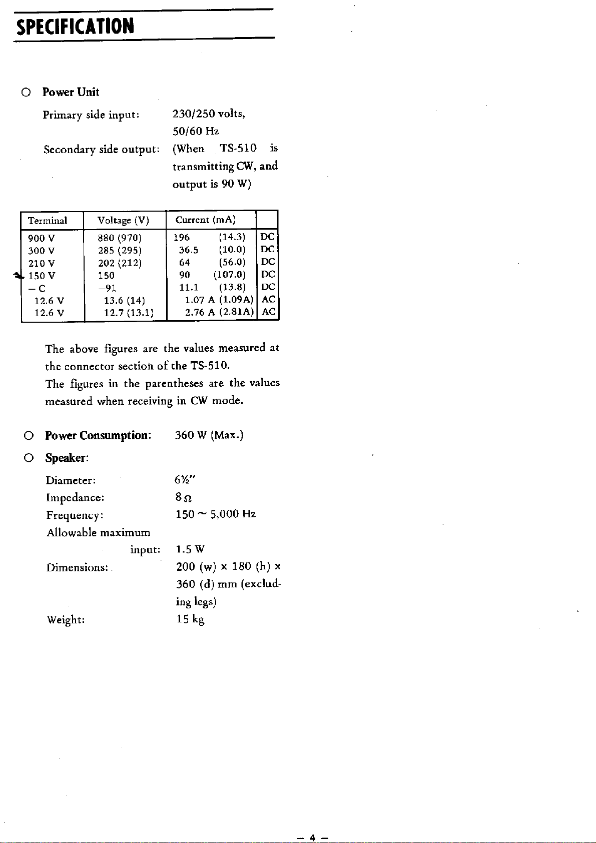
SPECIFICATION
PowerUnit
Primary
sideinput:230/250volts,
50/60Hz
Secondaryside
output:
(When
TS-510
is
transmitting
CW,
and
output
is90W)
Terminal
Voltage(V)
Current
(mA)
900V 880(970) 196(14.3)
DC
300V 285(295) 36.5(10.0)
DC
210V 202(212) 64(56.0)
DC
.
150V 150 90
(107.0)
DC
-
C
-91
11.1(13.8)
DC
12.6V 13.6(14) 1.07A (1.09A)
AC
12.6V 12.7(13.1) 2.76A (2.81A)
AC
The
abovefiguresarethevaluesmeasuredat
theconnectorsectionofthe
TS-510.
The
figuresinthe
parentheses
arethevalues
measuredwhenreceivinginCW
mode.
Power
Consumption:
360W
(Max.)
Speaker:
Diameter:6V2"
Impedance:8fi
Frequency:150~ 5,000Hz
Allowable
maximum
input:1.5W
Dimensions:.200(w)x 180(h)x
360(d)mm
(exclud-
ing
legs)
Weight:15kg
_
4 _
Table of contents
Popular Power Supply manuals by other brands

Videx
Videx 520MR Installation instruction

Poppstar
Poppstar 1008821 Instructions for use

TDK-Lambda
TDK-Lambda LZS-A1000-3 Installation, operation and maintenance manual

TDK-Lambda
TDK-Lambda 500A instruction manual

Calira
Calira EVS 17/07-DS/IU operating instructions

Monacor
Monacor PS-12CCD instruction manual


