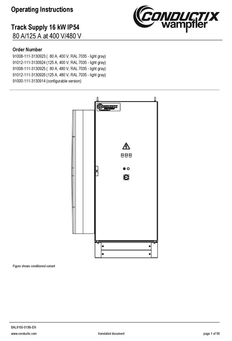
Conductix-Wampfler 91008-111-3090873 User manual

Operation Manual
Track Supply 6 kW
80 / 125 A at 400 / 480 V
BAL9100-0124c-EN
www.conductix.com Page 1 of 44
Order Number
91008
-111-3090873 ( 80 A, 400 V, RAL 7016)
91012
-111-3090875 (125 A, 400 V, RAL 7016)
91008
-111-3090876 ( 80 A, 480 V, RAL 7016)
91012
-111-3090878 (125 A, 480 V, RAL 7016)
91000
-111-3090877 (Configurable version)

Operation Manual
Track Supply 6 kW
80 / 125 A at 400 / 480 V
BAL9100-0124c-EN
www.conductix.com Page 2 of 44
Index Page
1Understanding........................................................................................................................................................................5
2Symbols and hints.................................................................................................................................................................5
3Advisory information for the user........................................................................................................................................6
4Brief technical description....................................................................................................................................................7
5Appearance ............................................................................................................................................................................7
6Technical data........................................................................................................................................................................9
6.1 Electrical data - specifications..................................................................................................................................................9
6.1.1 Electrical output data – specifications for 400 V and 480 V versions ......................................................................................9
6.1.2 Electrical input data – specifications for 400 V versions ..........................................................................................................9
6.1.3 Electrical input data – specifications for 480 V versions ........................................................................................................10
6.2 Physical data..........................................................................................................................................................................10
6.3 Environmental data ................................................................................................................................................................11
6.4 Mechanical data.....................................................................................................................................................................12
6.5 Interfaces ...............................................................................................................................................................................13
6.6 General features ....................................................................................................................................................................13
6.7 Design standards...................................................................................................................................................................14
6.7.1 Design standards for 400 V versions.....................................................................................................................................14
6.7.2 Additional design standards for 480 V versions.....................................................................................................................14
6.8 Safety features of Track Supply.............................................................................................................................................14
6.9 Grounding ..............................................................................................................................................................................14
7Control board hardware and failure indication.................................................................................................................15
7.1 Track Supply Control Board...................................................................................................................................................15
7.1.1 Control board LED indication.................................................................................................................................................15
7.2 Track Supply Display Board...................................................................................................................................................16
7.2.1 LED indication........................................................................................................................................................................16
7.2.2 Software Version Number......................................................................................................................................................17
7.2.3 Modes of Operation ...............................................................................................................................................................18
7.2.4 Setting Language, Time and Date .........................................................................................................................................18

Operation Manual
Track Supply 6 kW
80 / 125 A at 400 / 480 V
BAL9100-0124c-EN
www.conductix.com Page 3 of 44
7.2.5 Warning Messages ................................................................................................................................................................19
7.2.6 Error Codes............................................................................................................................................................................19
8Fuses.....................................................................................................................................................................................22
9Transport and storage.........................................................................................................................................................22
10 Installation............................................................................................................................................................................23
10.1 Who is authorized to carry out the installation? .....................................................................................................................23
10.2 General advice for the installation..........................................................................................................................................23
10.3 Place and conditions of installation........................................................................................................................................24
10.4 Electrical regulations..............................................................................................................................................................24
10.5 Electrical connection ..............................................................................................................................................................25
10.5.1 Mains connection ...................................................................................................................................................................25
10.5.2 Configuration of control plug..................................................................................................................................................26
10.5.3 Connection track cable (X1)...................................................................................................................................................27
10.5.4 Arrangement external connections (X2, X3, X4)....................................................................................................................27
10.5.5 Wiring of the Track Supply.....................................................................................................................................................28
10.5.6 Wiring of the Track Supply.....................................................................................................................................................29
11 Warnings and cautions .......................................................................................................................................................30
12 Commissioning....................................................................................................................................................................31
12.1 System conditions..................................................................................................................................................................31
12.2 System protection ..................................................................................................................................................................31
13 Start and operation..............................................................................................................................................................32
14 Switching-off ........................................................................................................................................................................33
15 Actions in case of emergency ............................................................................................................................................33
16 Fault diagnosis.....................................................................................................................................................................34
17 Maintenance .........................................................................................................................................................................35
18 Repair....................................................................................................................................................................................36
19 Disassembly / Re-use..........................................................................................................................................................37
19.1 Safety advice for disassembly and disposal ..........................................................................................................................37
19.2 Recycling ...............................................................................................................................................................................37
20 Spare parts ...........................................................................................................................................................................38

Operation Manual
Track Supply 6 kW
80 / 125 A at 400 / 480 V
BAL9100-0124c-EN
www.conductix.com Page 4 of 44
21 Tools .....................................................................................................................................................................................39
Adjustments during the commissioning and start-up..................................................................................................................40
Inspection report _____________________ ...................................................................................................................................41
Inspection report _____________________ ...................................................................................................................................42
Inspection report _____________________ ...................................................................................................................................43
Important:
Company names mentioned in this manual that are registered and protected trade names by copyright do remain the
property of the companies themselves.
We reserve the right to carry out technical modifications of illustrations and statements in these operating instructions, in
order to improve the energy supply system and its function.
System related details please find in the system manuals. Refer always to the system documentation before starting any
work on the system or components within the system or before operating the system.
Reprint and duplication (as well as extracts) are only allowed with permission from Conductix-Wampfler GmbH.
Conductix-Wampfler GmbH 2009

Operation Manual
Track Supply 6 kW
80 / 125 A at 400 / 480 V
BAL9100-0124c-EN
www.conductix.com Page 5 of 44
1Understanding
This document (BAL) describes the component specified on the cover only. The manual does not include details about the
interaction of this component with other IPT®components within a system.
For information relating to the system please read the system and project documentation. Follow these instructions during any
work on the system or operation of the system.
All given values are based on the metric system. Given dimensions without any measuring unit are generally in millimeters (mm).
2Symbols and hints
Warning of voltage
This symbol can be found in several places in the operating instructions where special care has to be taken
due to a voltage presence which is hazardous to people. Please observe these instructions and be careful in
those cases. Please apply all health and safety regulations to other users as well. Always disconnect the
system from the main supply prior to carrying out any work on the energy supply system.
Attention - some hints
This sign draws the attention to parts of the operating instructions where the regulations, advice and correct
operational sequence must be observed to avoid any damage or destruction to the energy supply system
and its components.
Temperature
This sign draws the attention to parts of the operating instructions, where special care must be taken
because of hot surfaces or where inductive heating of ferromagnetic material may occur and where special
measures have to be taken.
Please pass on the advice to other users as well.

Operation Manual
Track Supply 6 kW
80 / 125 A at 400 / 480 V
BAL9100-0124c-EN
www.conductix.com Page 6 of 44
3Advisory information for the user
When the Track Supply is open it can contain live voltage and hot surfaces, depending on its protection class
and state of operation.
Non-permissible removal of required covers, improper operation, faulty installation or operation involve risk
of severe injuries to a person and damage to components.
The Track Supply has a weight of approx. 56 kg and must not be lifted or moved by an individual person. To
move and position it use only suitable equipment and follow the according instructions (see chapter 6
“Technical data”).
All electric installation and commissioning work as well as repair work and disassembly have to be carried
out by qualified staff (IEC 364 respectively CENELEC HD 384 or DIN VDE 0100 and IEC 664 or DIN VDE
0110 and national safety rules).
All installation and commissioning work as well as repair work and disassembly have to be done according to
the present operation manual. The specifications of this document have to be strictly observed. In addition,
national regulations and whenever they apply regulations specific to the industry are to be taken into
account.
Qualified staff, according to the safety regulations, are persons who are familiar with the installation,
assembly, commissioning and operation of the energy supply system and who have the appropriate
qualifications.
Conductix-Wampfler GmbH cannot be responsible for damage or breakdowns that have been caused by not
observing the instruction manual.
These operating instructions contain exclusively details of the Track Supply component.
We reserve the right to carry out technical modifications of illustrations and statements in this instruction
manual. References to other IPT®documents specifying the document number do not include the revision
index. Refer to the project handbook for a list of relevant documents.

Operation Manual
Track Supply 6 kW
80 / 125 A at 400 / 480 V
BAL9100-0124c-EN
www.conductix.com Page 7 of 44
4Brief technical description
The Track Supply serves to supply energy to the secondary components of the IPTsystem in a defined
segment.
The Track Supply converts the 400 V 50 Hz or 480/277 V 60 Hz mains voltage to a constant 20 kHz
sinusoidal current. The alternating output current into the primary track of an IPTsystem produces a local
magnetic field over which power is transferred. So the galvanically isolated power transfer to the consumers
is possible (e.g. to the pickups).
5Appearance
Display-Window
Status-LED’s
Access fuses
Main air outlet
Air outlets
Access Track Cable
Power and Control Plugs

Operation Manual
Track Supply 6 kW
80 / 125 A at 400 / 480 V
BAL9100-0124c-EN
www.conductix.com Page 8 of 44
View without front lid
Note that the picture above may not in some cases correspond exactly to the delivered component (for example color or wiring
positions). If you have concerns you have not been delivered the correct item please contact a Conductix-Wampfler representative.
Display Board
Bolt terminals for track (max. 10 Nm)
Track Cable
Transformer
24 V Supply
Control Plug
RS232 Diagnosis Plug
Power Plug
AC line fuse disconnect
Control Board

Operation Manual
Track Supply 6 kW
80 / 125 A at 400 / 480 V
BAL9100-0124c-EN
www.conductix.com Page 9 of 44
6Technical data
6.1 Electrical data - specifications
6.1.1 Electrical output data – specifications for 400 V and 480 V versions
•Continuous output power 6 kW
•Overload capability 137% (8 kW) for max. 1 minute / 10 minute at 40°C,
with average load derating to 4.9kW
•Output current 80 A or 125 A ±2A @ 20 kHz ±50 Hz
•Optimal load track inductance 58 µH +2 µH for 80 A Track Supplies
26 µH +2 µH for 125 A Track Supplies
•Nominal output voltage range 560 - 665 V rms (80 A), 380 - 475 V rms (125 A). Overloads will increase the voltage.
•Impedance output to PE 180 Ohm (center capacitively referenced)
•Connection to primary cable Stainless Steel M8 bolts for 35 mm² and 20 mm² HF Litz cables. Torque range 9-10 Nm.
6.1.2 Electrical input data – specifications for 400 V versions
•Input nominal supply voltage 400 V / 50 Hz, 3-phase symmetric, neutral grounded
•Supply voltage tolerance -10% to + 10%, with proportional cont. power de-rating for input
voltages other than nominal value
•Efficiency at rated load 94%
•Power factor (cos ϕ) 0.78
•Supply current 12 A at rated power / voltage
•Input connector Supplied HAN-6HSB in Han-16B connector with PG 21 or M25
cable gland. Maximum outside cable diameter is 18 mm. Use
flexible cable 6 mm2.
•Input leakage current 16 mA rms in standby. Occasional 200 mA peak pulses for 250 µsec
at rated load. Ground leakage equipment must be rated accordingly if
used.
•Internal fuses 16 A gS or gRL. Semiconductor and wiring protection.
•Harmonic currents (rated load) 5th -4.5dB, 7th -9dB, 11th -21.6dB, 13th -21.7dB (on fundamental)

Operation Manual
Track Supply 6 kW
80 / 125 A at 400 / 480 V
BAL9100-0124c-EN
www.conductix.com Page 10 of 44
6.1.3 Electrical input data – specifications for 480 V versions
•Input nominal supply voltage 480 V / 60 Hz, 3-phase symmetric, neutral grounded
•Supply voltage tolerance -10% to + 10%, with proportional cont. power de-rating for input
voltages other than nominal value
•Efficiency at rated load 94%
•Power factor (cos ϕ) 0.78
•Supply current 10 A at rated power / voltage
•Input connector Supplied HAN-6HSB in Han-16B connector with PG 21 or M25
cable gland. Maximum outside cable diameter is 18 mm. Use
flexible cable 6 mm2.
•Input leakage current 19 mA rms in standby. Occasional 200 mA peak pulses for 250 µsec
at rated load. Ground leakage equipment must be rated accordingly if
used.
•Internal fuses 12A JKS, HSJ, DFJ Fast Class J
•Harmonic current (rated load) 5th -4.3dB, 7th -9.1dB, 11th -18.7dB, 13th -19.7dB (on fundamental)
6.2 Physical data
•Noise levels During operation 65 dBA at 1m distance in front
•Air volume moved 50 m³ / hour (air recirculation)
•Fan 3 axial fans

Operation Manual
Track Supply 6 kW
80 / 125 A at 400 / 480 V
BAL9100-0124c-EN
www.conductix.com Page 11 of 44
6.3 Environmental data
•Ambient temperature +5°C to +40°C, power de-rating 3% / °C between 40°C and 55°C
•Humidity < 90% non-condensing
•Ambient air No salt water, no conductive dry or wet dust! (e.g.
carbon fibers). Avoid extreme environment conditions
(e.g. very dusty, Oily and/or chemical influences)!
•Altitude de-rating 1% of power / 100 m above 1000 m, up to a max. of
3000 m above sea level
•IP classification IP 20 (limited by exhaust vents on top and other ventilation openings)
•Pollution Degree PD = 2. Non conducting pollution present, that may become temporarily conducting if
moisture is present after switching off.
•Storage temperature -20°C to +60°C
•Transport temperature -20°C to +70°C
•Maximum Vibration 3 mm at 2 - 9 Hz, max. acceleration 0,5 g at 9 - 200 Hz
•Maximum operating shock 8 g, 11 ms
•Maximum shipping shock 15 g, 11 ms in packaging / transport box
The Track Supply requires for correct cooling a sufficient air flow.
Ensure free air flow at all times and if Track Supply is mounted in a
cabinet inspect filters for dust and oil blockage regularly.
Shielded control cables are not strictly required but to improve the
EMC are recommended.
In order to avoid induced voltages at 20 kHz, the control cables and
other cables should not be run close to the IPT®track cable and
especially not over distances > 5 m. Shielded twisted pair cable will
help reduce the capacitive coupling effect. The shield should be
grounded at one end only.
•Space around cabinet Sufficient air flow has to be guaranteed!
Recommended clearances:
200 mm over the Track Supply
200 mm in front of the Track Supply
100 mm sides of the Track Supply
Air in
Air out

Operation Manual
Track Supply 6 kW
80 / 125 A at 400 / 480 V
BAL9100-0124c-EN
www.conductix.com Page 12 of 44
6.4 Mechanical data
•Cabinet Sheet metal housing
•Dimensions see the following drawing
•Nom. color housing (outside) RAL XXXX; delivered color see type plate on Track Supply *
•Weight ~ 56 kg
Dimensions
* = Colors are configurable prior to production.

Operation Manual
Track Supply 6 kW
80 / 125 A at 400 / 480 V
BAL9100-0124c-EN
www.conductix.com Page 13 of 44
6.5 Interfaces
Track connection (X1)
Pin
Function
Remarks
1
Track cable 1
20 (80 A) - 35 (125A) mm² lug
HF Litz cable *
2
Track cable 2
* = cable shoes with M8 hole, Soldered only!
Connection to AC mains supply (X2); Harting HAN-6HSB / Han-16B Housing
Pin
Function
Rating
Remarks
1
L1
12 / 10 A
I depending on load and input voltage
2
L2
12 / 10 A
I depending on load and input voltage
3
L3
12 / 10 A
I depending on load and input voltage
PE
PE
Control and synchronization (X3); Harting HAN-10E
Pin
Function
Rating
Remarks
1
Start +
24 V
24 V present = start
2
Start -
0 V
3
/Reset +
24 V
0 V = reset
4
/Reset -
0 V
5
ErrorRelay
1 A
24 V
Normally closed, open on error
6
Error Relay
7
24 V supply
100 mA Not for external distribution!
8
0 V
9
Synchronization
+15 V
10
Synchronization
For more details on X1, X2 and X3 and their connection refer to chapter 10.5 “Electrical connection”.
6.6 General features
•Input line chokes will drop 4% from the mains voltage at rated load
•EMC filtering Built in line filter included
•Start-up inrush current < 10 A
•Mains to output isolation High frequency isolation transformer
•Internal cooling fans 3 axial fans

Operation Manual
Track Supply 6 kW
80 / 125 A at 400 / 480 V
BAL9100-0124c-EN
www.conductix.com Page 14 of 44
6.7 Design standards
6.7.1 Design standards for 400 V versions
•EN 50178
•EN 61000-6-2
•EN 55011
6.7.2 Additional design standards for 480 V versions
•UL 508A Standards for Industrial Control Panels
6.8 Safety features of Track Supply
•Over temperature 4 In-built temperature sensors and switches
•Over load Output load monitoring
•Over current Internal current monitoring
•Over voltage Output voltage monitoring
•Ground fault detection Level adjustable
•Current sensor failure detect Detects if track current sensor is not functioning correctly
•Track detuning Monitors track and detects if the tuning is out of range
•Input line loss Detects if line phase is missing
•Fuses Integrated fast fuses
•Input to output isolation 2500 V AC for 1 min
6.9 Grounding
The Track Supply has to be grounded professionally at the installation place and connected preferably to a symmetrical neutral
grounded three-phase WYE supply. Although the Track Supply may well function in supply systems with other grounding, such as
grounded delta, the electromagnetic compatibility and reliability may be compromised.
Metal structures which run close and parallel to the IPT®primary track cable over significant distances have to be grounded
professionally too. For best results multiple grounding should be applied. In order to avoid induced voltages at 20 kHz, the control
cables and other cables should not be run close to the IPT®track cable and especially not over distances > 5 m. Shielded twisted
pair cable will help reduce the capacitive coupling effect, but the shield should be grounded at one end only.

Operation Manual
Track Supply 6 kW
80 / 125 A at 400 / 480 V
BAL9100-0124c-EN
www.conductix.com Page 15 of 44
7Control board hardware and failure indication
7.1 Track Supply Control Board
The control board is located in the upper part of the Track Supply and is visible if the door of the cabinet is open.
There are two PCB’s:
• The control board
• The display board sitting on top of the
control board
refer to section 7.2
7.1.1 Control board LED indication
The control board LEDs are normally only visible when the door is open and/or the protective covers have been removed.
Therefore these LEDs are intended for advanced error analysis only.
The two green LEDs (V503 and V504) indicate the correct functioning of the on-board power supplies (12 V and 5 V) and should
always be on.
The 4 LEDs on the control board inform the user of
the state of operation of the Track Supply:
•SYNC (green LED)
•ON (green LED)
•WARNING (yellow LED)
•ERROR (red LED)
The indication of the ‘On’, ‘Warning’ and ‘Error’ LEDs corresponds to the one of the three LEDs located on the Track Supply
display board (refer to section 7.2.1).
In addition the ‘Sync’ LED indicates whether an external 20 kHz synchronization signal is present or not.

Operation Manual
Track Supply 6 kW
80 / 125 A at 400 / 480 V
BAL9100-0124c-EN
www.conductix.com Page 16 of 44
7.2 Track Supply Display Board
The Track Supply display board has a backlit 3x16
character display, 3 LEDs and two push buttons for
user interaction assembled.
7.2.1 LED indication
The behavior of the three display board LEDs is as follows:
LED green
Status
Cause
Off Track Supply not powered or
error see red LED
Possible causes:
•Track Supply is disconnected from the mains power
•
Problem with control board
Flashing Track Supply in standby
mode
Normal condition due to absence of START signal on HAN-10E
On Track Supply is running
Normal condition: START and RESET signals are present on
HAN-10E
LED red
Status
Cause
Off Track Supply not powered or
no error see green LED
Normal condition if there is no error.
Flashing
Track Supply in reset mode
Normal condition due to absence of RESET signal on HAN-10E
On Track Supply error see
yellow LED / LCD
See display for error code. Error codes are described in
section 7.2.6 below.
The yellow LED warns the user of critical operating conditions. No warning will stop operation of the Track Supply, however, a
persistent warning may subsequently lead to an error if left unattended. If more than warning is present at a time, only the most
‘Mode’ button
‘Set’ button
3x16 LCD

Operation Manual
Track Supply 6 kW
80 / 125 A at 400 / 480 V
BAL9100-0124c-EN
www.conductix.com Page 17 of 44
important one will be shown (in the table below importance increases from top to bottom). Example: if tuning and overload warning
both are present, the warning LED will be on. The LCD, however, will display both warnings (see section 7.2.5).
LED yellow
Status
Cause
Off
No warnings
1 brief flash
every 2 s Real Time Clock warning
Real Time Clock has stopped due to weak battery and may be out
of date. Track Supply will continue to operate, however, errors will
no longer be time stamped correctly.
2 brief flashes
every 2 s Tuning warning
Track inductance is too low or too high. Track Supply can continue
to operate, however, an over temperature condition may result.
Causes:
•Incorrect commissioning
•Pickups added after commissioning
•Damaged track tuning capacitors
•Track/ Feeds repositioned or lengthened
Flashing slowly
Over temperature warning
One or more of the following causes:
•Air intake or exhaust blocked
•Fan(s) blocked by dust or defect
•Heat sink blocked by dust
•Overloading, too many loads
•Ambient temperature too high
Track Supply will continue to operate, however, an over
temperature condition may result.
On Overload warning
Too many loads on track. Track Supply will continue to operate,
however, an over temperature, over current or over voltage
condition may result.
7.2.2 Software Version Number
After powering up the LCD displays for 5 seconds a welcome screen with software
revision number and compilation time and date.
The Track Supply may start operation prior to the expiry of 5 s delay depending on the
START input.
Version 1234567a
13:07
17-Mai-09

Operation Manual
Track Supply 6 kW
80 / 125 A at 400 / 480 V
BAL9100-0124c-EN
www.conductix.com Page 18 of 44
7.2.3 Modes of Operation
During operation the LCD provides basic information about the operating mode of the Track Supply. The following modes have
been defined:
The Track Supply is powered but does not receive a high level signal on its RESET
input. Output is disabled.
The Track Supply is powered but does not receive a high level signal on the START
input. Output is disabled.
The Track Supply is operating normally.
The Track Supply detected an error. Error code with time and date of occurrence are
displayed. Refer to section 7.2.6 below for details on error codes
Output is disabled.
7.2.4 Setting Language, Time and Date
There are two buttons located beneath the LCD that allow the user to change basic settings. Settings may be changed in any
mode, except in RESET mode. If the RESET mode is entered (RESET input low) while settings are being changed, any changes
made are lost!
To start changing settings, the MODE key must be held down for 5 seconds. Once
this delay has expired the right hand screen will be displayed. Subsequent presses of
the SET key will step through the four available display languages:
•English
•German
•French
•Italian
Pressing the MODE key will advance to the next setting screen shown below.
The time setting is displayed in 24 h hh:mm format. The keys function as follows:
•Pressing or holding the SET key will increase the setting marked by the cursor.
•Pressing the MODE key will advance the cursor to the minute setting or the next
screen respectively.
SET TIME
15:01
hh:mm
SELECT LANGUAGE
English
-----ERROR------
E001 15:01
26.05.09
------RUN-------
No warnings
----STANDBY-----
No warnings
-----RESET------
No warnings

Operation Manual
Track Supply 6 kW
80 / 125 A at 400 / 480 V
BAL9100-0124c-EN
www.conductix.com Page 19 of 44
The date is displayed in dd.mm.yy format. The keys function as follows:
•Pressing or holding the SET key will increase the setting marked by the cursor.
•Pressing the MODE key will advance the cursor to the next setting or the next
screen respectively.
If any changes were made, the user is prompted to confirm or discard these.
•Pressing the MODE key will discard any changes.
•
Pressing the SET key will save the new settings, which is confirmed by the right
hand screen.
7.2.5 Warning Messages
While in modes RESET, STANDBY and RUN, additional warning messages may be displayed. These are reflected in the
indication of the yellow LED. If more than one warning is present at a time, warning messages will alternate every second. The
following warning messages are available:
•No warnings
•Warning Over load (Overload)
•Warning Over Temperature (Overtemp)
•Warning Tuning
•Warning RTC
Refer to section 7.2.1 for a detailed description and possible causes.
7.2.6 Error Codes
Note that one and the same problem can lead to different error codes, depending on the time of occurrence. This is because the
error detection methods and reaction times differ for each type of error and also due to the mainly sequential processing by the
microprocessor. Once an error is detected, subsequent errors are ignored.
Error code
Description
Meaning/Cause
E001 Phase loss
•Input line phase missing or weak
•Blown line fuse(s)
•
Fuse receptacle is not shut or screwed down properly
E002 IGBT error
•IGBT or IGBT driver board defective
•EMC disturbance
•
400 V TS used on 480 V supply
E003 Internal current hardware limit
•High peak load
•Track is open circuited
•
Track is detuned
Settings saved!
SAVE ?
Yes No
SET DATE
26:05.09
dd:mm:yy

Operation Manual
Track Supply 6 kW
80 / 125 A at 400 / 480 V
BAL9100-0124c-EN
www.conductix.com Page 20 of 44
Error code
Description
Meaning/Cause
E004 Ground fault
•Isolation of Track Supply or track installation damaged.
•Water present on track
•
Ground fault level set too low.
E005 Door open
•Pins 11 and 12 of X104 not bridged
•
Loose connection
E006
No track current
•Track current sensor defect or wire broken
E007 Temperature high on sensor 1
•Air intake or exhaust blocked
•Overloading, too many loads
•Ambient temperature too high
•Damaged track tuning capacitors
•
Axial fan defect / Fan fuse blown
E008
Temperature high on sensor 2
See E007
E009 Temperature sensor 1 defect
•Defect sensor
•
Loose connection
E010 Temperature sensor 2 defect
•Defect sensor
•
Loose connection
E011
Temperature high on heat sink sensor 1
See E007
E012
Temperature high on heat sink sensor 2
See E007
E013 Heat sink temperature sensor 1 short
circuited
•Temperature sensor wiring problem
E014 Heat sink temperature sensor 1 open
circuited
•Temperature sensor wiring problem
E015 Heat sink temperature sensor 2 short
circuited
•Temperature sensor wiring problem
E016 Heat sink temperature sensor 2 open
circuited
•Temperature sensor wiring problem
E017 Temperature switch 1 open circuited
•Loose connection
•
See E007
E018 Temperature switch 2 open circuited
•Loose connection
•
See E007
E019 LCD
•LCD defect
•
Loose connection between display and control boards
E020
Output (Track) voltage high
•Track is detuned
E021
Output (Track) current high
•Control board failure
E022
Output power high
•
Too many pickup loads on track
E023
Soft-start error
•Soft-start circuit failure
E024
Watchdog
•
Software problem
E025 Brownout
•Control board supply voltage failure
•
Control board on-board power supply failure
This manual suits for next models
4
Table of contents
Other Conductix-Wampfler Power Supply manuals