Trio JR900 User manual
J-Series Ethernet Radio
User Manual

Page 2
J-Series Data Radio – User Manual
Issue 09-10
Part F – Quick Reference Guide 34
Introduction 34
Mounting and Installation Instructions 35
Physical Dimensions - Remote Ethernet Data Radio 35
Connecting Antennas and RF Feeders 36
J-Series Connections Layout 36
Power Supply Requirements 36
Communication Ports 37
Cable Termination 37
Serial Port A & B Ports 38
LED Indicators 39
J-Series Conguration (Web Interface) 40
Resolving Ethernet Conguration Problems 41
Multi Master Synchronisation 43
Text User Interface (TUI) 44
Spectrum Analyzer 48
SNMP 50
eDiagnostics 52
Part G – Quick Start Guide 54
Point to Point Ethernet Link Setup 54
Point to Point - TCP Serial Device Server Setup Guide 57
Point to Point - UDP (Unicast) Serial Device Server Setup Guide 58
Point to Multi-Point - UDP (Multicast) Serial Device Server Setup
Guide 59
Point to Multi-Point with Peer to Peer - UDP (Multicast to Multicast)
Serial Device Server Setup Guide 61
Part H – Installation & Commissioning 63
Optimizing the Antenna for Rx Signal 65
Commissioning 66
Part I – Firmware Updating 68
Part J – FCC Approved Antennas 70
Part K – Support Options 71
Website Information 71
E-mail Technical Support 71
Contents
Part A – Preface 3
Warranty 3
Important Notice 3
FCC Compliance Notices 3
Australian Compliance Notices 3
EU (ETSI) Compliance Notices 3
Part B – J-Series Overview 5
Introduction 5
Product Range 5
Features and Benets 5
Ordering Information 7
Standard Accessories 8
Part C – Network Types 9
Introduction 9
Point-to-Point Networks (PTP) 9
Point-to-Multipoint Networks (PTMP) 10
Point-to-Multipoint via KwikStream™ Repeater 11
Point to Point with LinkXtend™ Bridge (PTP/B) 12
Point to Multipoint via LinkXtend™ Bridge (PTMP/B) 13
Part D – Features 14
Features Useful for Optimizing Performance. 14
Multi-Access Point Synchronization 16
Digital Collision Avoidance 17
Retries and Retransmissions 17
Ethernet Trafc Filtering 18
Security 18
SmartPath™ 20
Diagnostics Tools 26
Text User Interface (TUI) 27
Spectrum Analyzer and Channel Lockout Facility 27
Legacy Serial Support 28
Part E – RF Planning and Design 31
Understanding RF Path Requirements 31
Examples of Predictive Path Modelling 31
Antennas 32
RF Feeders and Protection 33
Band Pass Filter (900MHz Only) 33

Page 3
J-Series Data Radio – User Manual
Part A - Preface
Part A – Preface
Warranty
All equipment supplied by Trio DataCom Pty Ltd (As of 1 January
2009) is covered by warranty for faulty workmanship and parts
for a period of three (3) years from the date of delivery to the
customer. During the warranty period Trio DataCom Pty Ltd shall,
at its option, repair or replace faulty parts or equipment provided
the fault has not been caused by misuse, accident, deliberate
damage, abnormal atmosphere, liquid immersion or lightning
discharge; or where attempts have been made by unauthorised
persons to repair or modify the equipment.
The warranty does not cover modications to software. All
equipment for repair under warranty must be returned freight paid
to Trio DataCom Pty Ltd or to such other place as Trio DataCom
Pty Ltd shall nominate. Following repair or replacement the
equipment shall be returned to the customer freight forward. If it is
not possible due to the nature of the equipment for it to be returned
to Trio DataCom Pty Ltd, then such expenses as may be incurred
by Trio DataCom Pty Ltd in servicing the equipment in situ shall be
chargeable to the customer.
When equipment for repair does not qualify for repair or
replacement under warranty, repairs shall be performed at the
prevailing costs for parts and labour. Under no circumstances shall
Trio DataCom Pty Ltd’s liability extend beyond the above nor shall
Trio DataCom Pty Ltd, its principals, servants or agents be liable
for the consequential damages caused by the failure or malfunction
of any equipment.
Important Notice
© Copyright 2008 Trio DataCom Pty Ltd All Rights Reserved
This manual covers the operation of the J-Series of Digital Ethernet
Data Radios. Specications described are typical only and are
subject to normal manufacturing and service tolerances.
Trio DataCom Pty Ltd reserves the right to modify the equipment,
its specication or this manual without prior notice, in the interest
of improving performance, reliability or servicing. At the time of
publication all data is correct for the operation of the equipment
at the voltage and/or temperature referred to. Performance data
indicates typical values related to the particular product.
This manual is copyright by Trio DataCom Pty Ltd. All rights
reserved. No part of the documentation or the information supplied
may be divulged to any third party without the express written
permission of Trio DataCom Pty Ltd.
Same are proprietary to Trio DataCom Pty Ltd and are supplied
for the purposes referred to in the accompanying documentation
and must not be used for any other purpose. All such information
remains the property of Trio DataCom Pty Ltd and may not be
reproduced, copied, stored on or transferred to any other media or
used or distributed in any way save for the express purposes for
which it is supplied.
Products offered may contain software which is proprietary to Trio
DataCom Pty Ltd. However, the offer of supply of these products
and services does not include or infer any transfer of ownership
of such proprietary information and as such reproduction or reuse
without the express permission in writing from Trio DataCom Pty
Ltd is forbidden. Permission may be applied for by contacting Trio
DataCom Pty Ltd in writing.
FCC Compliance Notices
FCC Part 15 Notice
This device complies with Part 15 of the FCC Rules. Operation
is subject to the following two conditions: (1) this device may
not cause harmful interference, and (2) this device must accept
any interference received including interference that may cause
undesired operation.
This device must not be modied in any way or FCC compliance
may be void.
FCC Approved Antennas
This device can only be used with Antennas listed in Appendix I
of this J-Series User Manual. Please Contact Trio Datacom if you
need more information or would like to order an antenna.
RF Exposure
To satisfy FCC RF exposure requirements for mobile transmitting
devices, a separation distance of 26 cm or more should be
maintained between the antenna of this device and persons during
device operation. To ensure compliance, operations at closer
than this distance is not recommended. The antenna used for this
transmitter must not be co-located in conjunction with any other
antenna or transmitter.
MAXIMUM EIRP
FCC Regulations allow up to 36 dBm effective isotropic radiated
power (EIRP). Therefore, the sum of the transmitted power (in
dBm), the cabling loss and the antenna gain (in dBi) cannot exceed
36 dBm.
FCC Point to Point : More EIRP may be allowed for xed point to
point links. With the transmitter set to 27dBm, an antenna gain
(subtracting cable loss) of up to 15 dBi is allowed. For antenna
gains of more than 15 dBi in a xed point to point link, the power
must be backed off from 27dBm by 1dB for every 3dB the antenna
gain exceeds 15dBi.
Australian Compliance Notices
MAXIMUM EIRP
ACMA Regulations allow up to 30 dBm (1 Watt) of effective
isotropic radiated power (EIRP) in the 915MHz license free band
and 36 dBm (4 Watts) of EIRP in the 2.4GHz band. Therefore, the
sum of the transmitted power (in dBm), the cabling loss and the
antenna gain cannot exceed the above stated EIRP limits.
EU (ETSI) Compliance Notices
RF Exposure
2.4GHz Model : To satisfy EU (ETSI) requirements, a separation of
3cm should be maintained between the antenna of this device and
persons during operation.
MAXIMUM EIRP
ETSI Maximum EIRP for the 2.4GHz band is +20dBm.
SAFETY
Warning: Where a JR240 is to be operated above 65oC ambient, it
must be installed in a restricted access location.

Page 4
J-Series Data Radio – User Manual
Issue 09-10
Part A - Preface
WEEE Notice (Europe)
This symbol on the product or its packaging indicates that this
product must not be disposed of with other waste. Instead, it is
your responsibility to dispose of your waste equipment by handing
it over to a designated collection point for the recycling of waste
electrical and electronic equipment. The separate collection and
recycling of your waste equipment at the time of disposal will help
conserve natural resources and ensure that it is recycled in a
manner that protects human health and the environment. For more
information about where you can drop off your waste equipment
for recycling, please contact the dealer from whom you originally
purchased the product.
Dieses Symbol auf dem Produkt oder seinem Verpacken
zeigt an, daß dieses Produkt nicht mit anderer Vergeudung
entledigt werden darf. Stattdessen ist es Ihre Verantwortlichkeit,
sich Ihre überschüssige Ausrüstung zu entledigen, indem es
rüber sie zu einem gekennzeichneten Ansammlungspunkt
für die Abfallverwertung elektrische und elektronische
Ausrüstung übergibt. Die unterschiedliche Ansammlung und
die Wiederverwertung Ihrer überschüssigen Ausrüstung zu der
Zeit der Beseitigung helfen, Naturresourcen zu konservieren
und sicherzugehen, daß es in gewissem Sinne aufbereitet wird,
daß menschliche Gesundheit und das Klima schützt. Zu mehr
Information ungefähr, wo Sie weg von Ihrer überschüssigen
Ausrüstung für die Wiederverwertung fallen können, treten Sie
bitte mit dem Händler in Verbindung, von dem Sie ursprünglich das
Produkt kauften.
Low Voltage Safety (Europe)
In order to comply with the R&TTE (Radio & Telecommunications
Terminal Equipment) directive 1999/5/EC Article 3 (Low Voltage
Directive 73/23/EEC), all radio modem installations must include an
external in-line lightning arrestor or equivalent device that complies
with the following specications:
• DC Blocking Capability - 1.5kV impulse (Rise Time 10mS,
Fall Time 700mS) (Repetition 10 Times) or 1.0kV rms 50Hz
sine wave for 1 minute.
The JR240 has been classied as SELV throughout. All ports
shall be connected to like circuits and shall not extend beyond the
building boundary of the host equipment unless connected via
an isolation unit compliant with the requirements of section 7 of
EN60950-1.
Important Notices for Class I, Division 2,
Groups A, B, C & D Hazardous Locations
Applies to models JR900-xxxxx-xHx(CSA Marked)
This product is available for use in Class I, Division 2, Groups
A, B, C & D Hazardous Locations. Such locations are dened in
Article 500 of the US National Fire Protection Association (NFPA)
publication NFPA 70, otherwise known as the National Electrical
Code and in Section 18 of the Canadian Standards Association
C22.1 (Canadian Electrical Code).
The transceiver has been recognised for use in these hazardous
locations by the Canadian Standards Association (CSA)
International. CSA certication is in accordance with CSA Standard
C22.2 No. 213-M1987 and UL Standard 1604 subject to the
following conditions of approval:
1. The radio modem must be mounted in a suitable enclosure so
that a tool is required to gain access for disconnection of antenna,
power and communication cables.
2. The antenna, DC power and interface cables must be routed
through conduit in accordance with the National Electrical Codes.
3. Installation, operation and maintenance of the radio modem
should be in accordance with the radio modem’s user manual and
the National Electrical Codes.
4. Tampering or replacement with non-factory components may
adversely affect the safe use of the radio modem in hazardous
locations and may void the approval.
5. A power connector with locking screws as supplied by Trio
Datacom MUST be used.
WARNING EXPLOSION HAZARD

Page 5
J-Series Data Radio – User Manual
Part B – J-Series Overview
Introduction
The advanced TRIO Datacom J-Series frequency hopping Ethernet
Data Radio sets the standard for professional high speed serial
data communications in the license free 900MHz and 2.4GHz
bands.
With maximum range and virtually unlimited system coverage due
to its unique LinkXTend™ network bridging and KwikStream™
high speed repeater capabilities, the industrial strength J-Series is
ideally suited for the most demanding point to multipoint and point
to point wireless SCADA and Telemetry applications.
The highly versatile J-Series also offers dual Ethernet ports with
TRIO TVIEW+ network wide diagnostics compatibility.
Product Range
The TRIO J-Series comprises of the following models:
- the JR900, which operates within the 915MHz license
free frequency band (country specic models apply),
and
- the JR240 that can be congured for use in the
2.4GHz license free bands available throughout the
world.
Part B – J-Series Overview
J-Series Ethernet Data Radio
Features and Benets
Outstanding and highly versatile operational
capability:
• Point to point and point to multi-point operation
• Congurable personality – access point-remote-bridge-repeater
• KwikStream™ high speed single radio repeater mode *
• Unlimited coverage networks
• No restriction on the number of radios in any system
• Unique dual antenna LinkXtend™ technology increases
usable range
• Repeater and Bridge units support locally connected user
devices
• ChannelShare™ collision avoidance for unsolicited
remote transmissions allowing simultaneous polling and
spontaneous reporting
* Up to 140km (90 miles) single repeater system range with
6dB antennas (900MHz)
A Radio and Modem that extends performance
boundaries:
• License free operation in 900MHz & 2.4GHz ISM frequency
bands
• 512k high speed over-air data rate [900MHz version only] (can
be reduced to 256k for longer range)
• Robust, frequency hopping spread spectrum technology for
superior interference immunity
• Ultra Long Range high performance receiver *
• 1 Watt maximum allowable transmitter power (900MHz version
only)
• Advanced error free data delivery with CRC plus selectable
FEC and ARQ
• Multi-Access Point synchronization mode for interference
reduction with co-located Access Point radios
• High VSWR protection (900MHz version only)
* Up to 70km (45 miles) maximum single hop line-of-sight range
with 6dB antennas (900MHz)

Page 6
J-Series Data Radio – User Manual
Issue 09-10
Part B – J-Series Overview
Comprehensive and adaptable Ethernet
interfacing, control and transmission:
• 2 x Independent Ethernet ports (Auto MDI/MIDX)
• 10/100Mbps Interface (auto-detecting)
• Suitable for most Ethernet/IP protocols (including UDP, TCP,
DHCP, ARP, ICMP, STP, IGMP, SNTP & TFPT)
• IEEE 802.3 including dual port Ethernet Bridging functionality
• Flexible Ethernet routing providing optimum radio channel
efciency
• Auto or Manual DHCP conguration
• NTP Client/Server Time Synchronization Support
• Legacy RS-232 serial support via embedded terminal servers
(UDP/TCP)
Total command of the radio system with embedded
HTML web server:
• Network Management and Remote Diagnostics with no software
installation required!
• All conguration via secure embedded HTML interface (HTTP &
HTTPS)
• Network wide access from any radio modem
• Over-the-air reconguration & diagnostics
• Powerful system commissioning and troubleshooting tools
• Compatible with Trio TVIEW+ Diagnostics for stand alone
network management.
• Local and Remote eld upgradeable rmware
Securing your network through Trusted Access
Control:
• 256-bit AES data encryption (export restrictions may apply)
• Proprietary multi-level scrambled over-the-air protocol
• Optional Trusted Access Point/Remote checklist
A Ethernet Data Radio for the harshest
environments and places:
• Reliable operation in environmental extremes (-40oC to +70oC)
• Hazardous Environment Certication – CSA Class I, Division II
• FCC & ETSI certication - accepted in multiple regions
• Compact, rugged alloy housing
• 10-30Vdc power supply
• Dual industry standard TNC antenna connectors
Page 7
J-Series Data Radio – User Manual
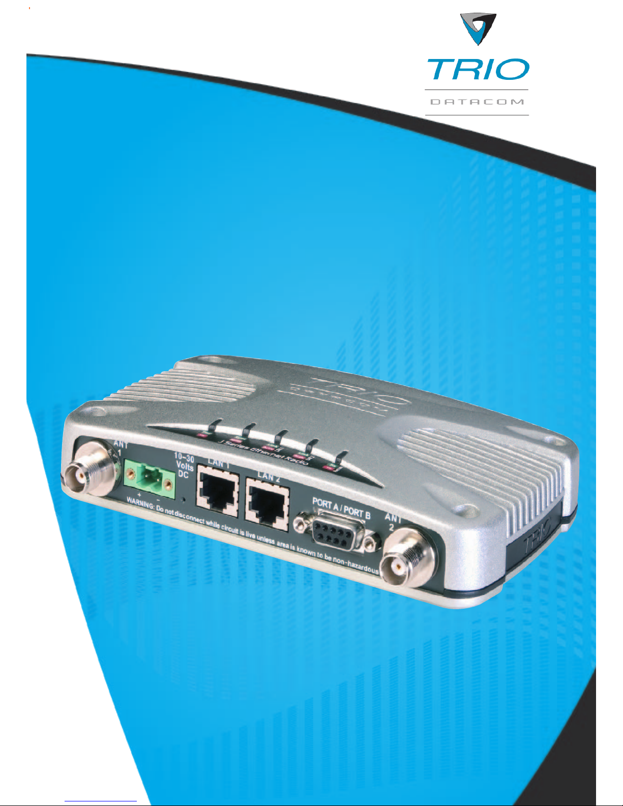
Ordering Information
J, K & O Series License Free Data Radios - Part Number Matrix = Tyxxx-aabbb-cde
T y xxx
-aa bbb
-cd e
Options 3
J&K Series
0= No Options
O Series
0= O Series configured for OEM
1= O Series configured for K Series
2= O Series configured for J Series
Options 2
0= No Options
H= Hazardous Environment Class 1, Div 2 (Standard on JR900, KR900 & OM900)
A= ATEX II 3G, Ex nA IIC T4 compliance (Standard on JR240, KR240 & OM240)
Options 1
D= Diagnostics (Inc. remote firmware update)
E= Diagnostics and Encryption (Inc. remote firmware update) ***
RF Channel Data Rate & Bandwidth (Internal Modem)
K&O Series
J Series
001
= 32kbps to 256kbps
002
= 256kbps to 512kbps
Frequency Range (900MHz) Frequency Range(2.4GHz)
00 = License Free Band 902 to 928MHz (FCC) 00 = License Free Band 2.4Ghz (FCC/IC/Aust/NZ & others)
01 = License Free Band 915 to 928MHz (Aust/Brasil) 01 = License Free Band 2.4Ghz (ETSI)
02 = License Free Band 921 to 928MHz (NZ)
Note: Other frequency bands available upon request.
Generic Frequency Band
900 = 900MHz
240 = 2.4GHz
Unit Type NOTES:
R= Remote Station (J&K Series Only) [ ] Items in [ ] parenthesis refer to actual Trio part numbers
M= OEM Module (O Series Only) ** Consult factory for availability.
*** Export Restrictions May Apply
`Standards: ACA - Australian Communications Authority
FCC - Federal Communications Commission
Model Type ETSI - European Telecommunication Standards Institute
J= J Series Family
K= K Series Family
O= O Series Family
Example:
K R 900
-00 001
-DH 0
Dwg / Ver: 194-56-0000-H
The example shown specifies: K Series, Remote Radio, 900MHz band, FCC,
configurable 32kbps to 256kbps modem, with diagnostics and Class 1, Div 2
Hazardous Approval (standard).
Part B – J-Series Overview

Page 8
J-Series Data Radio – User Manual
Issue 09-10
Part B – J-Series Overview
Standard Accessories
Part Number Description
Antennas
ANT9AL Antenna Yagi 6 Element 9dBd Alum 850-
930MHz
ANT9SS Antenna Yagi 6 Element 9dBd S/S 850-930MHz
ANT13AL Antenna Yagi 15 Element 13dBd Alum 850-
930MHz
ANT13AL Antenna Yagi 15 Element 13dBd S/S 850-
930MHz
ANT900WHIP Antenna Omni-Dirn Whip TNC - Demo Use 902-
928MHz
ANT915OMNI Antenna Omni-Dirn Unity Gain 902-928MHz
ANT2G4/13A Antenna Yagi Enclosed 13dBd Gain 2.4GHz
ANT2G4/16A Antenna Grid Reector 16dBd Gain 2.4GHz
ANT2G4/24A Antenna Grid Reector 24dBd Gain 2.4GHz
ANT2G4WHIP Antenna Omni-Dirn Whip TNC - Demo Use
2.4GHz
ANT2G4OMNI Antenna Omni-Dirn Unity Gain 2.4GHz
ANT2G4/6OM Antenna Omni-Dirn 6dBd Gain 2.4GHz
Note:
1. Frequencies must be specied at time of order.
Power Supplies
PS13V82A Power Supply 13.8V 2A 240VAC
PS13V82ASW Power Supply Switch Mode 13.8V 2A 110-
240VAC
Part Number Description
RF Cables and Accessories
RFCAB5M2 5.0m RG-213 type Antenna Feeder Cable
terminated with N type Male Connectors
RFCAB10M 10.0m RG-213 type Antenna Feeder Cable
terminated with N type Male Connectors
RFCAB20M4 20.0m LDF4-50 type (1/2” foam dialectric)
Antenna Feeder Cable terminated with N type
Male Connectors
LGHTARRST Lightning Surge Arrestor In-line N Female to N
Female DC<1000MHz
LGHTARRST2 Lightning Surge Arrestor In-line N Female to N
Female 2 to 6GHz
Software
TVIEW+ E,M&J-Series Conguration Programmer and
Cables

Page 9
J-Series Data Radio – User Manual
Introduction
Fundamental to understanding the use of J-Series Ethernet Data Radios in your system is the need for a basic understanding of the different types
of radio network topologies (known as NETWORK TYPES) and the function of each radio within them (known as RADIO TYPES).
The following table provides a brief overview of each:
Network Types:
Point to Point (PTP): One Access Point radio is congured to communicate with a REMOTE radio in PTP mode.
Point to Point via Bridge (PTP/B): As per PTP mode but with additional network range extension using a LinkXtend™ Bridge.
Point to Multipoint (PTMP): One Access Point radio is congured to communicate with multiple REMOTE radio(s) a PTMP network
Point to Multipoint with Bridges (PTMP/B): As per PTMP network but with additional network range extension using a LinkXtend™ Bridge.
Radio Types:
Access Point: Denes the Access Point radio in a network. The function of the Access Point is to provide synchronization of the network and
management of the radio protocol. There is always one Access Point per network.
Remote: A remote radio in the network. The function of a remote is to communication with the Access Point either directly or via one or more
Bridges.
Bridge: A radio that provides network extension between an Access Point or another BRIDGE and additional REMOTES. A BRIDGE is a
device with dual personalities, behaving as a REMOTE to its Access Point for 50% of the time, and then behaving as an Access Point for its
REMOTES for the remaining time.
Each type of network is described in the following diagrams.
Point-to-Point Networks (PTP)
A Point to Point (PTP) network has one Access Point and one Remote radio. The available data bandwidth is shared between the two radios in
each direction. Because a PTP network only has two radios, the over-the-air protocol can be optimized to provide best possible bandwidth, latency
and security.
Each hop is divided into two halves. The Access Point can transmit in the rst half and the Remote in the second half. This mode of operation is
called Pseudo Full Duplex due to the shared division of available bandwidth. Due to the well dened nature of channel access in PTP mode, data
collisions due to the Access Point and Remote trying to access the channel at the same time do not occur.
Pseudo Full Duplex has the advantage that it appears to the connected device to be a full duplex cable with a specic bandwidth (i.e: even if
one devices transmits continuously it will not block the other device from sending data). This is useful for applications that expect full duplex
communications or that are not designed to be radio modem friendly. The disadvantage of Pseudo Full Duplex is that the bandwidth is divided
equally for each direction, even if one direction does not use it’s available bandwidth.
Receipt of data (in either Access Point to Remote OR Remote to Access Point directions) is acknowledged by the receiving radio. This provides the
most efcient means of guaranteed data delivery as data does not need to be blindly “re-transmitted” which decreases the available bandwidth. For
more information on data acknowledgements and retransmissions refer to Part D - Features.
It is also possible to create a Point to Point (PTP) network using the Point to Multipoint (PTMP) Network Type and using only one Remote. In the
PTMP mode, system bandwidth is not shared equally, but when additional REMOTE sites are added at a future date, the existing radios will not
need to be re congured making additional Remote site deployment easier.
Part C – Network Types
Part C – Network Types

Page 10
J-Series Data Radio – User Manual
Issue 09-10
Point-to-Multipoint Networks (PTMP)
A Point to Multipoint (PTMP) network is normally chosen when one site (i.e.: The HOST) needs to broadcast messages to multiple REMOTE sites.
Point to Multipoint (PTMP) operation requires the Access Point site to have adequate RF coverage of all Remote sites which need to synchronize to
the Access Point. A PTMP offers the best available bandwidth and data latency when multiple remote sites are required.
Part C – Network Types
If used in conjunction with an exception reporting protocol (i.e.: DNP3) or when multiple applications are used on the network (i.e.: A DNP3 RTU on
Port A and a MODBUS PLC on Port B) it is possible for more than one Remote radio to attempt to access the Access Point at the same time. This
will cause data collisions, which requires the Remote radios to re-try their access to the Access Point. The result is a reduction in bandwidth and an
increase in latency.
To optmize the access to the Access Point in this scenario, it is strongly recommended to enable the ChannelShare™ collision avoidance
feature. The ChannelShare™ feature will minimize data collisions and increase effective throughput using a smart channel access strategy. More
information on ChannelShare™ digital collision avoidance technology can be found in Part D - Features of this manual.
The Access Point radio needs to be located at a site which has adequate RF coverage of all Remote sites. If this is not possible, then Point to
Multipoint via KwikStream™ Repeater is the preferred network topology.
The bulk of network specic radio conguration parameters are congured in the Access Point radio. Remote radios in the network “learn” these
conguration options from the Access Point. Remote radios can be added to the network without need to recongure the Access Point.
System wide diagnostics is available from any one remote to any other radio in the network.
It is recommended that omnidirectional antennas are used for the Access Point site and directional yagi antennas are used for REMOTE radio sites
as this will provide maximum system gain legally allowed.
Page 11
J-Series Data Radio – User Manual
Part C – Network Types
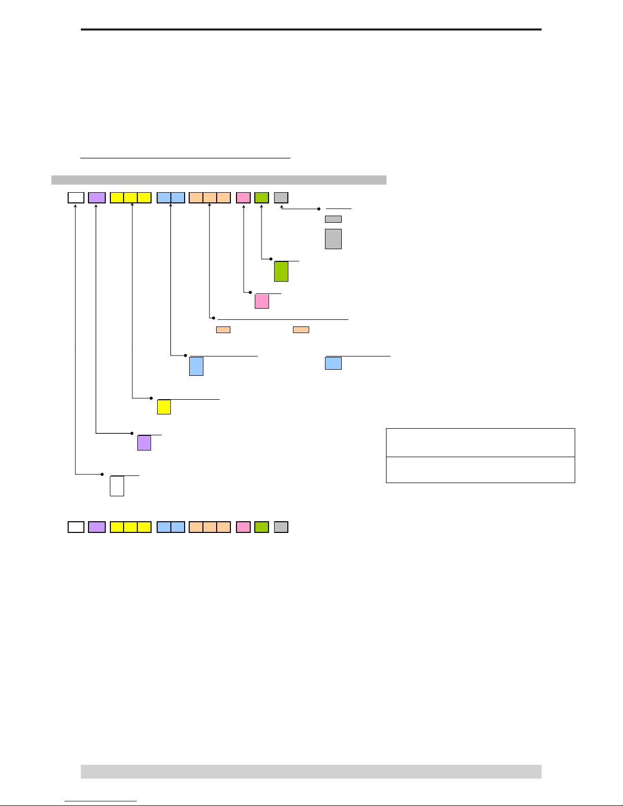
Point-to-Multipoint via KwikStream™ Repeater
A Point to Multipoint via KwikStream™ Repeater network is a variation of the Point To Multipoint network. It is normally chosen when the site where
the SCADA (i.e.: data) entry point does not have adequate RF coverage of other Remote sites in the network. The network diagram is shown below.
In this network topology, the Access Point radio is congured as a Repeater. The repeater should be located at a site with adequate RF coverage
to each of the remotes. The Repeater still behaves as an Access Point to the Remotes as in a Point to Multipoint network, but the Repeater is
congured to repeat data messages between remotes in the network. It therefore allows peer to peer communication to occur between remotes.
Because the Access Point radio now needs to “Repeat” data, data latency for messages from the Host Application to/from the Remotes will be
longer. However, the Repeater implements a smart repeating technology called KwikStream™ which allows the Repeater to perform multiple
transactions within any one hop, ensuring available bandwidth remains high and data latency is kept low. KwikStream™ technology is achieved
using a virtual “loop-back” plug ensuring data is repeated quickly and no user port with physical loop back plug is required. A key advantage is that
a local RTU/PLC device can be located at the Repeater site and peer to peer communication is supported for this unit.
For more information on KwikStream™ technology please refer to the appropriate section in Part D - Features of this user manual.
All other aspects of the Point to Multipoint network apply to this network topology.

Page 12
J-Series Data Radio – User Manual
Issue 09-10
Point to Point with LinkXtend™ Bridge (PTP/B)
The typical range of the Point to Point (PTP) Network Type can be extended using the Trio Datacom unique dual antenna LinkXtend™ technology.
This is achieved using a special radio mode called BRIDGING. A dual antenna LinkXtend™ bridge allows the maximum range possible from a
single radio store and forward technology whilst remaining within legal antenna EIRP limits. A typical Point to Point with Bridge network is shown
below.
The Point to Point with LinkXtend™ Bridge (PTP/B) type of network requires one Access Point, one or more Bridges and one Remote radio. The
Bridge operates in two different modes which alternate depending on what hop (odd or even) the hopping pattern is currently on.
During even numbered hops, the Bridge functions as a Remote to the network Access Point. Using the location of the Bridge in the network as a
reference point, any data sent from the Bridge to the Access Point is sent “Upstream”.
During odd numbered hops, the Bridge functions as an Access Point for the Remote radio. Using the location of the Bridge in the network as a
reference point, any data sent from the Bridge to the Remote is sent “Downstream”.
Thus a Bridge is a radio which functions both as a REMOTE and an Access Point in a time division multiplexed network.
When implementing this network it is important that the NETWORK TYPE is selected as Point to Point via Bridge (PTMP/B). This ensures the
network is divided up into multiple Sub-nets that supports the time division multiplexing of the system required by the Bridge. Each Sub-Net uses a
completely different hopping pattern so that multiple Bridges in the network will not interfere with each other.
Access Point to Bridge communication occurs on one Sub-Net whilst Bridge to Remote communication occurs on another Sub-Net. The Access
Point radio is responsible for network timing so that the Bridge is always operating in the correct mode ensuring data is not lost due to collisions
between Access Point and Remote.
Each additional bridge in the network requires the denition of a new Sub-net. For more information on Sub-Nets, refer to Section D of this user
manual. Network latency is doubled when compared to the latency of a network without bridges but due to the high speed nature of the J-Series
family, network latency is seldom an issue.
When Bridge mode is selected the radio can be congured for either a single antenna or dual antenna. Only on sites that require dual antenna
LinkXtend™ technology does a bridge need to operate in dual antenna mode. There are no limits to the number of bridges allowed in any one
network but additional Bridges will result in extra latency due to the time taken to transport data through the bridge.
It is recommended that omnidirectional and yagi antennas are used for BRIDGES (depending on network design) and directional yagi antennas are
used for Access Point and REMOTE radio sites as this will provide maximum system gain legally allowed. However, some sites where Bridges may
be located may not require the use of dual antennas and in these situations a single omnidirectional antenna can be used. For more information the
dual antenna port feature please refer to Part D of this User Manual.
All other aspects of the Point to Point (PTP) network previously mentioned apply to this type of network.
Part C – Network Types
Page 13
J-Series Data Radio – User Manual
Part C – Network Types
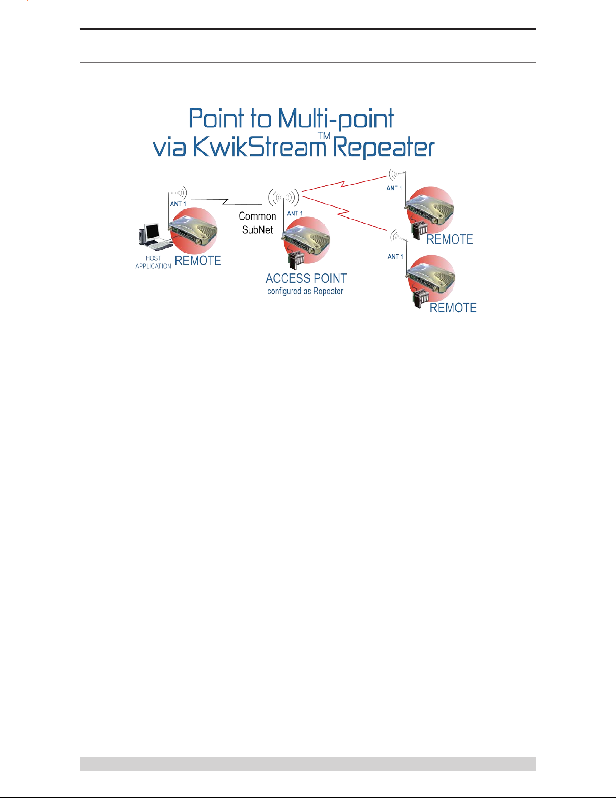
Point to Multipoint via LinkXtend™ Bridge (PTMP/B)
Note: It is recommended that you rst read Part C - Point to Multipoint (PTMP) Networks and Part C - Point to Point with LinkXtend™
Bridges before reading this section.
The typical range of the Point to Multi Point (PTMP) Network Type can also be extended using dual antenna LinkXtend™ technology. This is
achieved using Bridges which operate in the same way as described in Point to Point with LinkXtend™ Bridges (PTMP/B) networks. A typical Point
to Multi-Point with Bridge network is shown below.
This type of network includes an Access Point, two or more multiple Bridges and multiple Remote radios.
If used in conjunction with an exception reporting protocol (i.e.: DNP3) or when multiple applications are used on the network (i.e.: A DNP3 RTU
on Port A and a MODBUS PLC on Port B) it is possible for more than one Remote radio to attempt to access the same Bridge at the same time.
This will cause data collisions, and as such the it is recommended to use the ChannelShare™ collision avoidance feature. More information on
ChannelShare™ digital collision avoidance technology can be found in Part D of this manual.
The Point to Multipoint via Bridge network topology should only be chosen when two or more Bridges are required. If only one “Store and Forward”
site is required then the Point to Multipoint with KwikStream™ Repeater network topology offers more bandwidth and lower latency. However, the
LinkXtend™ dual antenna feature is only available when a Bridge network is selected.
Remote radios can synchronize to any Bridge or the Access Point in the network. The actual device the remote will synchronize to depends on the
Sub-Net ID specied in the remote radio. For more information on Sub-Net refer to Part D of this User Manual.
The bulk of network specic radio conguration parameters are congured in the Access Point radio. Remotes and Bridges in the network “learn”
these conguration options from the Access Point. Remotes and Bridges can be added to the network without need to recongure the Access
Point.
System wide diagnostics is available from any one remote to any other radio in the network.

Page 14
J-Series Data Radio – User Manual
Issue 09-10
Part D – Features
Features Useful for Optimizing
Performance.
In addition to the settings made to establish Radio Type, Network
Type and Subnet ID there are a number of parameters congured
in the Access Point radio that can optimize the performance of the
J-Series Ethernet radio network.
Over the Air Data
All Ethernet data sent over the air is packaged into data packets.
These data packets are transported over the network together with
a small amount of overhead (or management data).
The total amount of data sent in one single hop depends on the
hop interval, RF data rate and the amount of data that is waiting to
be sent. The larger the total amount of data, the smaller the ratio
overhead compared to user data.
In almost all situations the default settings of the radio will provide
the adequate performance. However, under some circumstances,
it may be necessary to ne tune specic features so an
understanding of how these features work is important.
Radio Data Rates
The radio data date determines the over the air speed of the
modem. Essentially it denes how much bandwidth is available.
The J-Series 900MHz version offers two selectable data rates.
256kbps with BER of 1E-6 @ -102dBm
512kbps with BER of 1E-6 @ -92dBm
The choice of radio data rates will depend on the level of RF
signal strength, but will also depend on other factors like RF noise.
In general, higher RF signal levels are required when using the
512kbps RF data date, otherwise an unreliable link may result.
It may be preferable to start at the lower speed of 256kbps and
change to 512kbps once the network is congured correctly.
The J-Series also provides the ability to have mixed data rates
in one system as shown in the diagram below. In this mode of
operation, the J-Series Access Point is congured for “Auto Radio
Data Rate”. Remote radios that have weak signal strength are
then congured for 256kbps data rates while those remotes with
stronger signal strength are congured for 512kbps data rates.
The conguration setting for radio Data Rates can be found in the
“Unit Parameters” section of the Radio conguration area of the
web programmer.

Page 15
J-Series Data Radio – User Manual
Part D – Features
Hopping Intervals
Frequency Hopping Spread Spectrum (FHSS) radios like the
J-Series operate in an unlicensed shared frequency band and
collisions can be expected when multiple radios are operating in
the same area.
Due to the hopping nature of the radio, the radio “hops” between
a specic number of distinct frequencies in a specic pattern. The
length of time that the radio remains on any one frequency is called
the “Hopping Interval”. Data is transferred between radios during
this time.
Once the hopping interval has expired, the transmitter (if active) is
stopped, and all radios in the system “hop” to the next frequency in
the hopping pattern. Whilst the radios are hopping, no data can be
transferred between radios.
When two radios in the same area are transmitting on the same
unique frequency, a data collisions may occur and this will prevent
successful data transfer until one or both radios “hop” onto another
frequency.
Shorter hop intervals will reduce the amount of time that any such
collisions may impact on the radio link and as such will make the
radio link less susceptible to interference. However, the usable
bandwidth of the radio will be reduced because the ratio of time
spent hopping to a new frequency vs time spent transmitting data
is higher.
Longer hop intervals will increase the amount of time that any such
collisions may impact on the radio link and as such will make the
radio link more susceptible to interference. However, the usable
bandwidth of the radio will be increased because the ratio of time
spent hopping to a new frequency vs time spent transmitting data
is lower.
The radio will default to a Hopping Interval of 100mS. For
most systems, this setting provides a good balance between
susceptibility to interference vs usable bandwidth.
Page 16
J-Series Data Radio – User Manual
Issue 09-10
Multi-Access Point
Synchronization
When more than one J-Series network shares the same physical
site (i.e: antennas for each network are in close proximity)
the Access Point radios can interfere with each other. This
interference may occur when one AP is transmitting while the
other AP is receiving. The problem is caused by receiver blocking
and desensitization.
To avoid this problem, all collocated Access Point radios can
be synchronised to transmit and receive at the same time using
a special multiple “Access Point” synchronisation feature. This
feature is enabled by conguring one Access Point radio as the
“multi-Access Point primary” Access Point and all other Access
Point radios as the “multi-Access Point secondary” Access Point.
A cable is installed between all APs which connects Pin 9 on
the Port A/Port B data port of all APs. Conguration jumpers
on the “primary” Access Point set it’s Pin 9 as an output. This
allows the “primary” AP to generate a synchronization pulse for
all “secondary” Access Points, dictating to them when they can
transmit and when they must return to receive mode. In this mode
of operation, the transmit/receive duty cycle is 50%.
When operating in this mode, all Access Point radios must have
the same hopping interval and have the appropriate conguration
for the General Purpose Pin 9 on Port B (See Port B - Advanced).
Multi-Access Point synchronisation divides each hop interval into
half - the rst half is a dedicated Access Point transmit time slot
and the second half is a dedicated receive timeslot. Because the
Access Points each have the same hop interval and each hop
interval begins at the same time (as synchronised by the primary
Access Point), no Access Point will transmit when the others are in
receive mode.
As such, there is no opportunity for desensitization and
interference is limited to a very low statistical probability of two
radios transmitting on the same frequency at the same time
Multi-Access Point synchronisation can also be used in a PTMP
system by itself (i.e.: even if there is only one Access Point) for the
purpose equally sharing the bandwidth in each direction (Access
Point to Remotes and Remotes to Access Point).
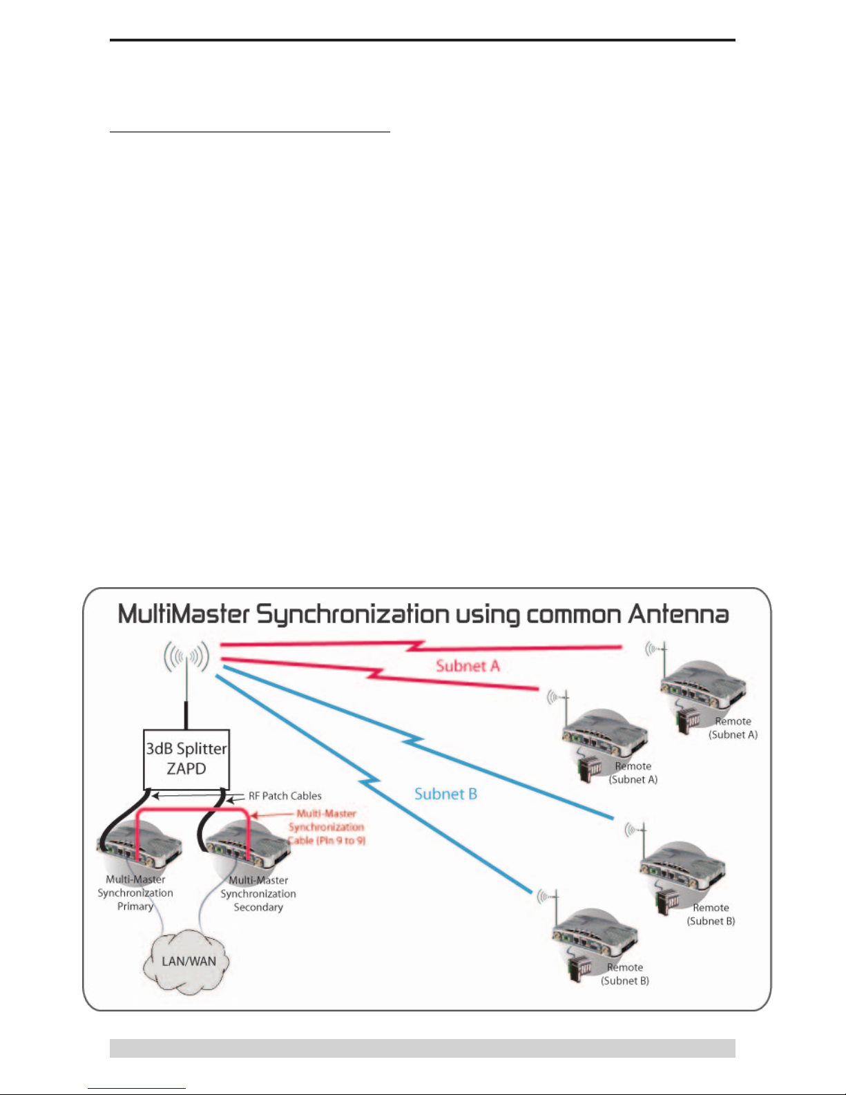
In some applications it is not possible to mount separate antennas
for each Access Point. This may be due to physical (ie: tower is
already loaded to capacity) or economic reasons (ie: too expensive
to mount multiple omnidirectional antennas) or for antenna
radiation pattern reasons (ie: best location for omni antennas being
at top of tower). In the above scenarios, it is desirable for multiple
Access Points to share one common antenna.
This can also be achieved by using a 3dB combiner/splitter as
shown in the diagram below. The 3dB combiner/splitter (Mini-
Circuits ZAPD-1 or similar) much provide >25dB of isolation
between ports and be capable of handling 1W (+30dBm EIRP) RF
input powers.

Page 17
J-Series Data Radio – User Manual
Digital Collision Avoidance
ChannelShare™
In some network applications there exists the potential for over the
air data collisions between REMOTE radios. This can occur when
an exception reporting type of protocol is used (such as DNP3) or
when multiple applications are being transported over the radio
network (such as MODBUS and DNP3).
In both of these scenarios, the possibility exists for two or more
REMOTE radios attempting to access the channel (i.e.: talk to
the Access Point) at exactly the same time. If this occurs, both
REMOTE radios are unaware of the other trying to access the
Access Point and both will attempt to transmit their data. As such,
the Access Point will received a corrupted message from both
radios and a re-try will be required.
ChannelShare™ digital collision avoidance is a type of Access
Point controlled channel access scheme that decreases the
possibility for over the air data collisions to occur. It achieves this
by having any REMOTE (or BRIDGE) with data that needs to
be transmitted request permission from the Access Point before
transmitting the data. The mechanism which is used to achieve this
is called a Token Grant.
Token Grants
When ChannelShare™ digital collision avoidance is enabled, the
Access Point radio (or BRIDGE that is behaving as an Access
Point for its DOWNSTREAM network) issues “Tokens” to each
REMOTE (or BRIDGE) radio that needs to transmit data.
When a REMOTE (or BRIDGE) radio has data packets that need
to be sent to an Access Point, it rst requests a TOKEN from the
Access Point (or BRIDGE) radio. When a TOKEN is requested,
the requesting radio includes the amount of data that needs to be
transmitted.
When the Access Point radio receives the TOKEN request, it
determines a suitable time when the requesting radio can access
the channel and transmit its data. The Access Point then grants a
TOKEN to the radio wants to access the channel, and the TOKEN
includes the serial number of the radio being granted, the starting
time and length for which the TOKEN applies. All other radios not
granted the TOKEN remain silent during the TOKEN period.
The function of the Access Point is to consider and manage all
TOKEN requests and only grant TOKENS in such a way that no
two devices accessing the channel will cause a collision.
TOKENs are granted to specic radios, based on their serial
number. As such, their is no opportunity for multiple radios to
become confused about what TOKEN has been granted.
The process of requesting “permission” to send data and receiving
the “OK to Send” response does result in increased data latency
and slightly slower data throughput. However, the practical reality
of systems where large amounts of exception reporting data need
to be handled mean the actual throughput perceived by the user is
much higher because the number of over the air data collisions is
signicantly lower.
All radios in the network also employ a small amount of random
channel access backoff timing so that when a TOKEN has expired,
requests for TOKENs to be granted are not themselves the subject
of a large number of over the air data collisions.
Retries and Retransmissions
No Ack Retries
Data transmitted from a REMOTE to an Access Point is
acknowledged by the Access Point. No Ack Retry Limit denes
how many times the REMOTE attempts to transmit data to an
Access Point if NO acknowledgement arrives from the Access
Point for the previous attempt by the REMOTE.
Once the No Ack Retry Limit is reached, the data is discarded by
the REMOTE. The important point to note is that the No Ack Retry
mechanism does not have any bandwidth penalties as it is only
required when interference prevents the successful delivery of data
to the Access Point radio.
Retransmissions
Except in PTP modes, data transmitted from an Access Point (or
BRIDGE) to a REMOTE is not acknowledged by the REMOTE.
Data Retransmissions dene how many times the Access Point
(or BRIDGE) duplicates (or re-transmits) data to the REMOTES.
The theory is that even if the REMOTE is subject to interference,
at least one of the messages will be received. Duplicate messages
are discarded by the REMOTE. Each data re-transmission results
in less usable bandwidth in the Access Point to REMOTE direction.
However, in a practical system it is a more efcient method of
preventing lost data than waiting for the SCADA system to timeout
and try again.
Force Retransmissions Across Hops
For increased reliability and protection from other radios operating
in the vicinity, it is possible to force the re-transmissions to occur in
different hops. The data is rst transmitted in one hop and then the
second re-transmission takes place on the next hop. This method
ensures that each re-transmission will be sent on a different
frequency within the hop pattern of the radio and so avoids xed
frequency interference. However, there is a larger decrease in
usable bandwidth in the Access Point to REMOTE direction when
re-transmissions are spread across multiple hops. To minimise
the loss of bandwidth, it is recommended to choose a shorter hop
interval.

Page 18
J-Series Data Radio – User Manual
Issue 09-10
Security
Frequency Hopping Spread Spectrum radios offer a high level
of security because it is not possible to eaves drop on data
transactions without knowing the hopping pattern being used and
having proprietary knowledge about how the data is encoded.
Unlike 802.11 and WiFi equipment which can be purchased “off the
shelf” the Trio J-Series employs many levels of defence against
security potential security threats.
Security Layers
The J-Series Radio employs several layers of security. Each layer
is detailed below.
(1) Network Name : The Network Name is used to derive the
hopping pattern. The Network Name must be identical in all
radios in the Network.
(2) Trusted Remotes/Access Points : If enabled, only serial
numbers in the Trusted Remotes/Access Points list can be
communicated with. Serial numbers are unique and factory
set. They can not be manipulated by the user.
(3) Encryption : All data is encrypted with a 256-bit AES
encryption key. If enabled, the same key MUST be used in all
radios.
Password Protected Web site Interface
When enabled the user will be required to enter a password to
enter the web site interface to access the conguration of the radio.
Trusted Access Points and Trusted Remotes
Trusted Remotes:
Access Point radios can be congured to communicate only
with a list of trusted REMOTE radios. If any serial numbers of
trusted remotes are entered into the “Trusted Remote List” then
communications will only occur with radios entered on this list. If
the list is empty, then communication can occur with any remote
and this security feature is disabled. Up to 63 trusted remotes can
be specied.
Trusted Access Points:
REMOTE radios can be congured to communicate only with a
list of trusted Access Point radios. If the Access Point radio serial
number is in the “Trusted Access Point” list the communication
can only occur to this Access Point. If the list is empty, then
communication can occur with any Access Point that has the
correct Network Name. Up to 4 trusted Access Points can be
specied.
By entering any serial number into either the “Trusted Remote” or
“Trusted Access Point” lists, this security feature is enabled and the
radios will only communicate with radios dened on their trusted
list, if these lists are empty the radios will communicate with any
radio having the correct network name.
Ethernet Trafc Filtering
As of rmware release V3.1, the J-Series radios implement several
features to reduce the amount of redundant on air trafc so that
higher actual bandwidths may be achieved. These features add no
additional latency to the network, they require no conguration and
improve bandwidth. As such they are always enabled.
Peer to Peer Repeat Filtering:
This feature greatly improves the available bandwidth in systems
where peer to peer connectivity is required. The ltering is
implemented in within the Access Point (or Bridge) of PTMP
or PTMP/B systems. Essentially it prevents the unnecessary
repeating of Ethernet trafc which is inherently point to point in
nature (ie: a TCP session).
When two remote radios need to communicate with each other
(often referred to as Peer to Peer), the Access Point (or Bridge) will
repeat the trafc to provide peer to peer connectivity.
However, if the trafc is from a Remote to an AP (or Bridge), then
peer to peer repeating is not required and the AP (or Bridge) does
not repeat the trafc. The AP (or Bridge) learns what devices (MAC
addresses) do not require repeating. Broadcast trafc is always
repeated. By learning where devices are located on the network,
the route table does not require any special conguration or setup.
Unicast Transmissions & Data Acknowledgements
This feature provides an improvement in downstream
bandwidth (ie: From AP to Remote) as it prevents unnecessary
retransmissions of data from AP to Remote (ie: retransmission
blindly transmit data multiple times). When the AP (or Bridge)
detects that data is being unicast (ie: sent to one remote device
only), the AP (or Bridge) swaps from retransmission of data (ie:
blindly sending data multiple times) to data acknowledgement
mode (No Ack Retires).
Essentially the AP (or Bridge) briey swaps to a PTP mode
of operation during the transmission of this unicast data. The
remote radio acknowledges this unicast data from AP which in
turn allows AP to send data to remote without the need for blind
retransmissions. The acknowledge process is described earlier in
this user manual. Refer to “No Ack Retries” in Part D.
When the AP (or Bridge) detects the trafc is of a broadcast or
multicast type, the AP (or Bridge) returns to normal PTMP mode
where trafc is retransmitted as per the normal process.
Upstream and Downstream Filtering for Bridge
Radios
This feature prevents unnecessary transmission of data either
upstream or downstream of a bridge. It is useful for systems where
Ethernet devices are connected to bridges. The bridge learns
which direction (either upstream or downstream) the trafc needs
to ow and lters out the trafc accordingly.

Page 19
J-Series Data Radio – User Manual
Part D – Features
Encryption
When encryption is enabled in a network, all data sent over the air
is protected from eavesdropping and can only be read by radios
sharing the same Encryption Key.
Encryption must be enabled in each radio in a network. The
encryption key is 256 bits long and is entered as string or a
hexadecimal number. For maximum security the key chosen
should be one that is difcult for an intruder to guess.
Once written into the radio using the programmer, it is not possible
to read the encryption key so care must be taken to record the key
in a safe place.
Encryption Key : String
For a string type of key, use up to a maximum of 32 printable
characters. Please note that the key is case sensitive.
Some examples are:
TRIO2008
Murray River Region
Encryption Key : Hexadecimal Number
Hexadecimal numbers can have a value of 0 to 15 and are
represented by 0-9 and A, B, C, D, E or F
A hexadecimal key begins with 0x and has up to 64 digits following
Some examples are:
0x123
0x123456789ABCDEF
0x11111111222222223333333344444444 up to 64 digits
Page 20
J-Series Data Radio – User Manual
Issue 09-10
Part D – Features
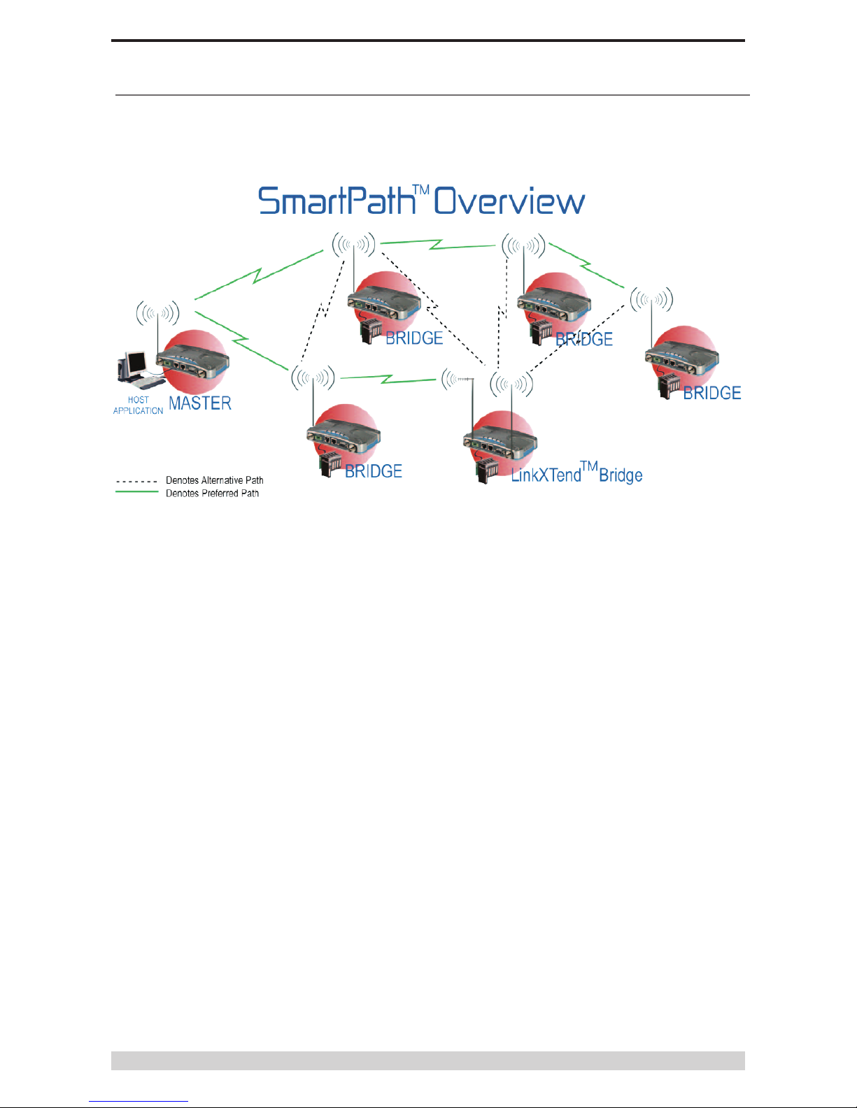
SmartPath™
The J-Series radio provides unique features to enhance connectivity and redundancy in both xed and mobile applications. Typical SCADA and
Telemetry systems require a high degree of radio link reliability. Using SmartPath™ features together with a small amount of system planning, the
system designer can create a network topology that provides for multiple alternative radio link paths. This type of network is often referred to as a
MESH network and a typical example is shown below. Note that the “Master” of the network for J-Series is referred to as the Access Point.
SmartPath™ has been optimized for SCADA and Telemetry systems, providing an ideal balance between connectivity (ie: link reliability), latency,
bandwidth and system design effort. Many peer to peer MESH networks are optimized for short range, high density networks. As a result, much
of their over-the-air bandwidth can be consumed in radio protocol management overhead (ie: keeping track of where peers are in the network, re-
conguration of priority paths, etc).
SmartPath™ only re-congures the network topology when it is required. During normal operation, the system designer can utilise all of the
over-the-air bandwidth and minimise message latency. Should one of the critical path radios fail, those radios dependent on that failed radio will
search for alternative paths via other radios. The system designer can optimise radio path connectivity using a preferred/alternative arrangement.
In applications where radios are mobile or roaming, SmartPath™ can provide an unlimited number of coverage areas including the ability to reliably
hand-over coverage from one radio to another based on usable received signal strength.
This manual suits for next models
1
Table of contents
Other Trio Radio manuals


