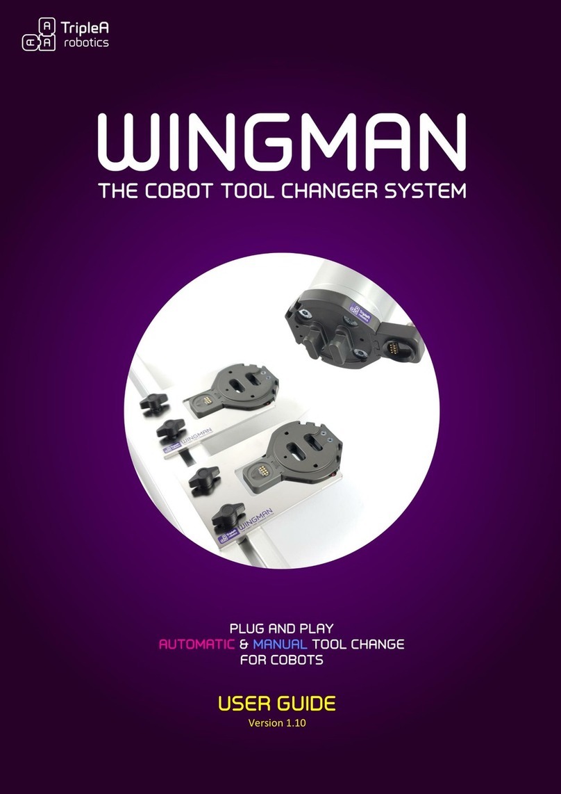
TripleA robotics Wingman User manual

Version 1.0

QUICK GUIDE
version 1.0
2 | P a g e
TripleA robotics makes flexible automation possible and profitable for high mix and low volume
production companies through Applicable, Adaptable and Affordable robotic tools.
1 Unboxing your kit
1.1 Manuel kit
The manual kit enables you to complete quick and easy manual exchange between two cobot tools and is
provided with all the necessary parts for installation on a cobot that is featured with the ISO 9409-1-50-4-
M6 tool flange like cobots from Universal Robots.
The manual kit is featured with pneumatic pass-through connections build into the housing. If additional
pass-through connectivity is needed, pass-thought modules are available for purchase. See available pass-
through modules in chapter Product Data in the end of the user guide.
Copyright © 2020 by TripleA robotics ApS. All rights reserved.

QUICK GUIDE
version 1.0
3 | P a g e
TripleA robotics makes flexible automation possible and profitable for high mix and low volume
production companies through Applicable, Adaptable and Affordable robotic tools.
1.2 Automatic kits
The automatic kits enables you to complete quick and easy manual and automatic exchange between two
cobot tools and is provided with all the necessary parts for installation on a cobot that is featured with the
ISO 9409-1-50-4-M6 tool flange like on cobots from Universal Robots.
The kits are featured with pneumatic pass-through connections build into the housing and can be included
with additional modules for electricity and for pneumatic/vacuum pass-through. See available automatic
kits and pass-through modules in chapter Product data in the end of the user guide.
(Example pictures of one of our standard kits(
Copyright © 2020 by Tr
ipleA robotics ApS. All rights reserved.

QUICK GUIDE
version 1.0
4 | P a g e
TripleA robotics makes flexible automation possible and profitable for high mix and low volume
production companies through Applicable, Adaptable and Affordable robotic tools.
2 Safety
WARNING! This quick guide only partly includes the safety information and other information necessary for correct and
safe install, setup and operation of the WINGMAN Tool Changer System. The full safety information is found in the user
guide which must always be read, understood, and followed in full. The product may not be used in any way based only
on the instructions found in this quick guide.
The user guide’s safety information is listed throughout the user guide where appropriate and in the dedicated
chapters: 1. Important safety notes and 9. Safety.
Before use, you must read, understand and comply with the safety instructions provided in the user guide. Among other
make sure that your cobot is certified for collaborative operation, that you have setup the cobot’s collaborative safety
settings correctly and that a full risk assessment of the whole robot application has been completed to local
legislation/standards.
Always ensure to use the product within its intended use. (User guide chapter: 6.1-6.4)

QUICK GUIDE
version 1.0
5 | P a g e
TripleA robotics makes flexible automation possible and profitable for high mix and low volume
production companies through Applicable, Adaptable and Affordable robotic tools.
3 Installing
Step 1. Bolt the tool changer robot part onto to the cobot arm and the tool parts onto the end-effectors.
(User guide chapter: 6.1-6.4)
Step 2. Install pneumatic and electrical connections for the end-effectors to test the end-effectors functionality
with connectivity through the tool changer parts. Make sure that the end-effectors work as expected and
that cables and hoses can be installed after good practice for such.
(User guide chapter: 6.4-6.5)
Step 3. Install the tool part holders and place the tool part and end-effector assemblies in the tool part holders to
make sure that there is space as appropriate. The tool part holders must be installed as instructed in the
user guide. (User guide chapter: 6.6)

QUICK GUIDE
version 1.0
6 | P a g e
TripleA robotics makes flexible automation possible and profitable for high mix and low volume
production companies through Applicable, Adaptable and Affordable robotic tools.
4 Manual use
WARNING! Before engage/disengage the tool changer’s robot part and tool part, make sure that all energy and control
to the end-effector has been turned off. Failing in doing so can cause serious injury and even death.
Step 1. Unlocked: Move both levers on the tool part (one on each side) with your fingers to the unlocked position
where the red markers on the levers are visible, and the green markers are not visible.
(Only one lever is shown in above illustration)
Step 2. Pre-locked: Engage the tool part with the robot part and PRESS on both levers with your fingers so that
they move to the pre-lock position where the red marker and the green marker are both visible on both
levers.
PRESS
Pre-locked position
WARNING! It is not allowed to deploy the tool changer when in pre-locked position as the tool changer
will not have full strength.
Step 3. Locked: PRESS again on both levers with your fingers to the locked position where only the green markers
are visible, and you feel a “click” as the levers move into place.
PRESS again
Locked position
Step 4. Unlocking is in the reversed order.
ATTENTION! Do not use hand tools of any kind such as screw drivers etc. to move the levers as this will
permanently damage the levers.
Copyright © 2020 by TripleA robotics ApS.
All rights reserved.

QUICK GUIDE
version 1.0
7 | P a g e
TripleA robotics makes flexible automation possible and profitable for high mix and low volume
production companies through Applicable, Adaptable and Affordable robotic tools.
5 Automatic use
WARNING! Before engage/disengage the tool changer’s robot part and tool part, make sure that all energy and control
to the end-effector has been turned off. Failing in doing so can cause serious injury and even death.
WARNING! Before you start programming and testing automatic tool changes, you must ensure to do it in a safe way.
Failing in doing so can cause hardware damage, injury and even death. Among other you must:
adjust the cobot’s robot limits (collaborative safety limits) to a setting that correspond to your risk assessment,
adjust the cobot’s speed to a low setting that allow you time to move free from moving parts,
prevent unintended/unexpected movement of the cobot and of the end-effector(s),
prevent incorrect energy levels to reach the end-effector (e.g. 24 volts to an end-effector designed for 12 volts)
and
ensure that the end-effectors you plan to deploy are suitable for automatic tool change.
In general, the user guides chapter “8.4 Good practice for setting up tool changes” must be followed.
Step 1. Uninstall all the cables, hoses and pass-through modules so you can proceed to setting up automatic tool
change without the risk of damage to cables, hoses and pass-through modules. Then program/teach the
cobot with the three waypoints (W1, W2 and W4) for each individual end-effector to achieve automatic
tool change (see next page). You might also consider programming/teaching waypoint W0, W3 and W5
depending on your application. See scheme in the next page.
Waypoint W2 is the reference point for the other waypoints, so program/teach waypoint W2 first and
from there move the cobot linear in the axial direction to program/teach W1 and from W2 in the radial
direction to teach/program W4 (and W3). Waypoint W4 can be programmed/teached with a slight incline
to lift the tool part free of the tool part holder.
Test the automatic tool change for each end-effector. Test at low cobot speed and in general be aware that
high speed will decrease life span and increase safety risks. Among other, the cobot’s speed must be
considered in the Integrators/users risk assessment.
(User guide chapter: 8.1 and 8.2)
Universal Robots users can deploy the optional URcap software provided by TripleA robots, which provide
1-minute automatic tool change setup as only waypoint W2 must be teached for each end-effector.
Follow the instructions provided in the URcap and in the user guide.
(User guide chapter: 8.5)

QUICK GUIDE
version 1.0
8 | P a g e
TripleA robotics makes flexible automation possible and profitable for high mix and low volume
production companies through Applicable, Adaptable and Affordable robotic tools.
WAYPOINTS
W0
ENTER PATH
(optional)
Use a waypoint to ensure free passage of the cobot arm into
and away from the tool space.
W1
DISENGAGED
(mandatory):
Robot part and tool part aligned on the same axis ready to
engage.
W2
TOOL HOLDER
(mandatory):
Robot part, tool part and tool part holder are FULLY
engaged. W2 is the reference waypoint for all other
waypoints. Fully engagement is important to ensure smooth
tool change.
WARNING! Energy and control (electricity,
vacuum, air pressure) for the end-effector must
be turned off before moving from W1 to W2
and before moving from W2 to W1.
W3
P
RE
-
LOCKED
(mandatory):
The tool changer is in pre-lock position. In this position the
payload and COG are toggled to fit the end-effector.
Default distance between W2 and W3 is 12 mm.
W4
Locked position
(mandatory):
The tool changer is in locked position. In this position other
end-effector parameters are toggles such as power supply,
TCP, Tool Voltage, Tool I/O’s etc.
W5
EXIT PATH
(optional):
Use a waypoint to ensure free passage of the cobot arm into
and away from the tool space.
Step 2. After testing that tool changes executes correctly, re-install the pass-through modules, cables and hoses to
provide connectivity to the end-effectors. Then setup the cobot to toggle parameters like voltage,
pneumatic and vacuum OFF before tool change takes place and ON after tool change has taken place. You
should toggle these parameters in waypoint W4 or W5.
WARNING! Before tool change takes place all electrical, pneumatic and vacuum must be turned OFF and
with no residual electricity, air pressure, vacuum etc. in the system. This is important to prevent hardware
damage and end-effectors unexpected movement which pose a risk of injury or even death.
The optional URcap software provide functionality to toggle power supply, TCP, Tool Voltage, Tool I/O’s
etc. (User guide chapter: 8.5.4)
Step 3. Now test the tool change and if necessary, adjust until you are satisfied with the tool change execution.
Then implement the remaining robot program to complete your application. Deploy the checklists
provided in the user guide before deploying your application into production. (User guide chapter: 9.8)
If you encounter issues, please consult the troubleshooting in the end of the user guide.
Other manuals for Wingman
1
Table of contents
Other TripleA robotics Robotics manuals
