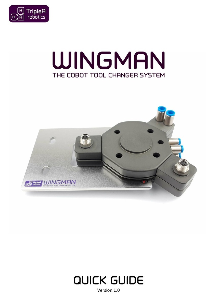
TripleA robotics Wingman User manual

USER GUIDE
Version 1.10

USER GUIDE
version 1.10
2 | P a g e
TripleA robotics makes flexible automation possible and profitable for high mix and low volume
production companies through Applicable, Adaptable and Affordable robotic tools.

USER GUIDE
version 1.10
3 | P a g e
TripleA robotics makes flexible automation possible and profitable for high mix and low volume
production companies through Applicable, Adaptable and Affordable robotic tools.

USER GUIDE
version 1.10
4 | P a g e
TripleA robotics makes flexible automation possible and profitable for high mix and low volume
production companies through Applicable, Adaptable and Affordable robotic tools.

USER GUIDE
version 1.10
5 | P a g e
TripleA robotics makes flexible automation possible and profitable for high mix and low volume
production companies through Applicable, Adaptable and Affordable robotic tools.
Table of Contents
TABLE OF CONTENTS ..................................................................................................................................................... 5
1IMPORTANT SAFETY NOTES ................................................................................................................................. 7
1.1 SIGNS.......................................................................................................................................................................... 7
1.2 MAIN WARNINGS...........................................................................................................................................................8
2DEFINITIONS ........................................................................................................................................................ 9
3TOOL CHANGER COMPONENTS AND ORDERING.................................................................................................11
4UNBOXING YOUR KIT ..........................................................................................................................................12
4.1 MANUEL KITS.............................................................................................................................................................. 12
4.2 AUTOMATIC KITS ......................................................................................................................................................... 13
5INTENDED USE ....................................................................................................................................................14
6INSTALLATION.....................................................................................................................................................15
6.1 INSTALLATION ENVIRONMENT,SPECIFICATIONS AND SAFETY ................................................................................................. 15
6.2 PRE-INSTALLATION PREPARATION....................................................................................................................................15
6.3 INSTALLING THE ROBOT PART..........................................................................................................................................15
6.4 INSTALLING THE TOOL PART............................................................................................................................................ 17
6.5 INSTALLING PASS-THROUGH MODULES .............................................................................................................................18
6.6 INSTALLING THE TOOL PART HOLDER ................................................................................................................................ 20
7MANUAL USE ......................................................................................................................................................23
7.1 LOCKING AND UNLOCKING ............................................................................................................................................. 23
8AUTOMATIC USE.................................................................................................................................................24
8.1 IMPORTANT ABOUT WAYPOINTS .....................................................................................................................................25
8.2 IMPORTANT ABOUT COBOT SPEED ................................................................................................................................... 26
8.3 IMPORTANT ABOUT END-EFFECTOR SELECTION AND PARAMETERS..........................................................................................26
8.3.1 The end-effector’s automatic tool change capability....................................................................................... 26
8.3.2 The end-effector’s energy requirements .......................................................................................................... 27
8.3.3 The end-effectors weight and center of gravity ............................................................................................... 27
8.4 GOOD PRACTICE FOR SETTING UP TOOL CHANGES ...............................................................................................................28
8.5 PROGRAMMING TOOL CHANGE ON UNIVERSAL ROBOTS COBOTS........................................................................................... 28
8.5.1 Preparation....................................................................................................................................................... 30
8.5.2 How the URcap software works ....................................................................................................................... 30
8.5.3 Basic setup of tool change movement.............................................................................................................. 32
8.5.4 Basic setup of end-effector parameters ........................................................................................................... 35
8.5.5 Powerful TEST feature and good programming practice ................................................................................. 37
8.5.6 Advanced: Setup of tool change movement..................................................................................................... 40
8.5.7 Advanced: Setup of end-effector settings......................................................................................................... 42
8.5.8 Advanced: Setup of odd orientation of the robot part ..................................................................................... 44
8.5.9 Advanced: Sharing end-effectors between more Robot Programs and cobots................................................ 45
8.5.10 Advanced: Remote activated automatic tool change ................................................................................... 46
8.6 PROGRAMMING TOOL CHANGE ON OTHER COBOTS............................................................................................................. 47
9SAFETY ................................................................................................................................................................48
9.1 LIMITATION OF LIABILITY: .............................................................................................................................................. 48
9.2 RESPONSIBILITY OF THE SYSTEM INTEGRATOR.................................................................................................................... 48
9.3 RESPONSIBILITY OF THE USER..........................................................................................................................................48
9.4 MAIN HAZARDS........................................................................................................................................................... 49
9.5 THE TOOL SPACE.......................................................................................................................................................... 50
9.6 COBOT REQUIREMENTS................................................................................................................................................. 51

USER GUIDE
version 1.10
6 | P a g e
TripleA robotics makes flexible automation possible and profitable for high mix and low volume
production companies through Applicable, Adaptable and Affordable robotic tools.
9.7 LOAD LIMITING AND COLLABORATIVE SAFETY SETTINGS........................................................................................................ 51
9.8 CHECKLISTS,RISK REDUCTION AND RESIDUAL RISKS .............................................................................................................51
9.8.1 Pre-deployment checklist and residual risk ...................................................................................................... 52
9.8.2 Startup checklist ............................................................................................................................................... 53
9.8.3 Interval checklist............................................................................................................................................... 53
9.9 ID TAG SYSTEM............................................................................................................................................................ 54
9.10 WARNING SIGNS ......................................................................................................................................................54
10 REPAIR AND MAINTENANCE ...............................................................................................................................55
10.1 LIFE SPAN AND MAINTENANCE.....................................................................................................................................55
10.1.1 Wear.............................................................................................................................................................. 55
10.1.2 Cleaning......................................................................................................................................................... 55
10.1.3 Lubing the tool changer ................................................................................................................................ 56
10.1.4 Lubing the pass-through modules ................................................................................................................. 56
10.2 DAMAGE AND REPAIR ................................................................................................................................................ 57
11 TROUBLESHOOTING............................................................................................................................................58
12 WARRANTY AND LIABILITY..................................................................................................................................62
12.1 PATENTS................................................................................................................................................................. 62
12.2 PRODUCT WARRANTY ................................................................................................................................................ 62
12.3 DISCLAIMER............................................................................................................................................................. 62
EC - DECLARATION OF INCORPORATION ......................................................................................................................63
DATASHEETS ................................................................................................................................................................64
DATASHEET -TOOL CHANGER..............................................................................................................................................70
DATASHEET -TOOL PART HOLDER .......................................................................................................................................74
DATASHEET -ELECTRIC PASS-THROUGH MODULE .............................................................................................................. 76
DATASHEET –HIGH FLOW PASS-THROUGH MODULE..........................................................................................................78
DATASHEET –URCAP SOFTWARE ............................................................................................................................................. 80

USER GUIDE
version 1.10
7 | P a g e
TripleA robotics makes flexible automation possible and profitable for high mix and low volume
production companies through Applicable, Adaptable and Affordable robotic tools.
1Important safety notes
1.1 Signs
Warning texts are important instructions to ensure human safety and must always be complied with.
Attention texts are important guidelines for best practice that will prevent hardware damage and ensure a long life
span of your product.
Tip texts are tips that will ensure you the best user experience.
Copyright © 2020 by TripleA robotics ApS. All rights reserved.

USER GUIDE
version 1.10
8 | P a g e
TripleA robotics makes flexible automation possible and profitable for high mix and low volume
production companies through Applicable, Adaptable and Affordable robotic tools.
1.2 Main warnings
WARNING! You must read, understand, and follow all safety information in this user guide, and the robot
manual and all associated equipment before initiating robot motion. Failure to comply with safety
information could result in serious injury or even death.
WARNING! The information in this user guide does not cover designing, installing, and operating a
complete robot application, nor does it cover other peripheral equipment that can influence the safety of
the complete system. It is the system integrators responsibility that the complete system is designed and
installed in accordance with the safety requirements set forth in the standards and regulations of the
country where the product covered in this user guide is installed.
WARNING! Any safety information provided in this manual must not be construed as a warranty, by
TripleA robotics ApS, that the robot application will not cause injury or damage, even if the robot
application complies with all safety instructions.
WARNING! TripleA robotics ApS disclaims any and all liability if any of TripleA robotics ApS products are
damaged, changed or modified in any way. TripleA robotics ApS cannot be held responsible for any
damages caused to any of TripleA robotics ApS products, the robot, or any other equipment due to
programming errors or malfunctioning of any of TripleA robotics ApS products.
WARNING! The system integrator and user must observe and comply with the “SAFETY” chapter before
the robot application is deployed.

USER GUIDE
version 1.10
9 | P a g e
TripleA robotics makes flexible automation possible and profitable for high mix and low volume
production companies through Applicable, Adaptable and Affordable robotic tools.
2Definitions
cobot
Cobots, or collaborative robots, are robots intended to interact with humans in a shared
space or to work safely in close proximity. Cobots are usually also very easy and fast to
setup and program.
collaborative applications
A collaborative application is a cobot application where the cobot is installed and
deployed without a physical safety guard protecting humans.
collaborative operation
Collaborative operation is a state in which purposely designed cobots work in direct
cooperation with a human within the defined workspace.
collaborative workspace
Collaborative workspace is the space within the safeguard space where a cobot and a
human can perform tasks simultaneously during production operation.
Controller
A controller is an electrical devise with terminals for I/O’s and a computer logic between
the Input(I) and the outputs(O). Usually a cobot is delivered with a controller. A controller
can also be a separate control unit that provide control of pneumatic flow etc.
End-effector
An end-effector is a robot tool / service specially designed for attachment to a cobot’s
mechanical interface (tool flange) to enable the cobot to perform its task. Example:
Gripper, nutrunner, welding gun, dispenser, screwdriver etc.
I/O’s
“I” stands for Input and “O” stands for Output. I/O is a brad term covering all electrical
Input and Output connectivity and control between a controller and an end-effector.
Installed Center of Gravity
(ICoG)
The ICoG is the center of gravity for the tool part(WINGMAN Tool Changer part) and the
end-effector assembly perceived as one body as this is installed in the tool part
holder(WINGMAN Tool Changer part). The location of the tool part + end-effector body's
ICoG will depend on the angle in which the tool part holder is installed.
System integrator
A System Integrator is a person or an entity who installs and deploys a robot application,
such as a collaborative application. In case the end-user (person or entity) installs and
deploys a robot application, the end-user will be the System Integrator and have the
System Integrators’ responsibilities among other to safety approve the application.
Pass-through connectivity
Pass-through connections
Pass-through modules
Pass-through connectivity are means (pass-through modules) that allow energy and
control such electricity, pneumatic and vacuum to flow to/from the end-effector. Tool
changers for automatic use will need to facilitate the necessary pass-through
connectivity.
Robot limits
A cobot’s robot limits is a set of threshold limits that will result in a protective stop of the
cobot if exceeded. Robot limits can be but is not limited to threshold limits associated
with:
- Power limit.
- Force limit.
- Speed limit.
protective stop
A protective stop is a type of interruption of a cobot's operation that allows a cessation of
motion for safeguarding purpose and which retains the program logic to facilitate a
restart.

USER GUIDE
version 1.10
10 | P a g e
TripleA robotics makes flexible automation possible and profitable for high mix and low volume
production companies through Applicable, Adaptable and Affordable robotic tools.
Quasi-static contact
Transient contact
Quasi-static contact and transient contact are two types of potentially harmful (human
injury) contact that are defined and handled in standard ISO/TS 15066:2016.
Quasi-static contact is a human limb being pinching between a fixed object and a moving
object such as a cobot.
Transient contact is a human being hit by a moving object such as a cobot.
residual risk
Residual risk is the risk that remains after all planned risk reducing initiatives have been
ensured. A collaborative application will have a residual risk that must be accepted by the
System Integrator and the user before the collaborative application can be deployed.
teach-in
Teach-in is a feature that some cobots have and that allow the user to program the
cobot's motion in a simple way by moving the cobot to waypoints by hand.
teach pendant
A cobot teach pendant is a computerized control panel that allows a user to set up and
program the cobot. A teach pendant is usually connected to the cobot wia a cable.
tool changer system
Atool changer system is a complete system of parts, that allow a user to complete
manual or automatic tool changes in a quick and easy way.
tool space
The tool space is a space surrounding the rack that stores the end-effectors when these
are not attached to the cobot. The tool space is safeguarded by robot limits only. As the
user is NOT allowed to access the tool space while the cobot is in operation, the tool
space cannot be perceived as part of the collaborative workspace.
URcap software
An URcap software is a piece of software that can be use with Universal Robots (UR) only
and provides an intuitive graphic user interface (GUI) that runs directly on the UR teach
pendant in the original UR software named Polyscope.
Waypoint
A waypoint is a X, Y, Z coordinate and RX, RY, RZ rotation of a cobot's tool flange in space.
A cobot moves between such waypoints.

USER GUIDE
version 1.10
11 | P a g e
TripleA robotics makes flexible automation possible and profitable for high mix and low volume
production companies through Applicable, Adaptable and Affordable robotic tools.
3Tool changer components and ordering
In this chapter, you will find a brief presentation of each component in the WINGMAN Tool Changer System. To find
more details on components, please visit the chapter Product data in the end of this user guide.
To order components:
1. Identify the part number(s) you need.
2. Contact your local distributor or visit TripleA robotics website and fill out the online quote form.
www.TripleA-robotics.com
Copyright © 2020 by TripleA robotics ApS. All rights reserved.

USER GUIDE
version 1.10
12 | P a g e
TripleA robotics makes flexible automation possible and profitable for high mix and low volume
production companies through Applicable, Adaptable and Affordable robotic tools.
4Unboxing your kit
4.1 Manuel kits
The manual kit enables you to complete quick and easy manual exchange between cobot tools and is
provided with all the necessary parts for installation on a cobot that is featured with the ISO 9409-1-50-4-
M6 tool flange like cobots from Universal Robots, Techman robots and other.
The manual kit is featured with pneumatic pass-through connections built into the housing. If additional
pass-through connectivity is needed, pass-thought modules are available for purchase. See available pass-
through modules in chapter Product data in the end of this user guide.
Copyright © 2020 by TripleA robotics ApS. All rights reserved.

USER GUIDE
version 1.10
13 | P a g e
TripleA robotics makes flexible automation possible and profitable for high mix and low volume
production companies through Applicable, Adaptable and Affordable robotic tools.
4.2 Automatic kits
The automatic kits enable you to complete quick and easy manual and automatic exchange between
cobot tools and is provided with all the necessary parts for installation on a cobot that is featured with the
ISO 9409-1-50-4-M6 tool flange like on cobots from Universal Robots, Techman robots and other.
The kits are featured with pneumatic pass-through connections build into the housing and can be included
with additional modules for electricity and for pneumatic/vacuum pass-through. See available automatic
kits and pass-through modules in chapter Product data in the end of this user guide.
Example picture of one of our standard kits (case is optional)

USER GUIDE
version 1.10
14 | P a g e
TripleA robotics makes flexible automation possible and profitable for high mix and low volume
production companies through Applicable, Adaptable and Affordable robotic tools.
5Intended use
The WINGMAN Tool Changer System is intended for industrial use with collaborative robots from Universal
Robots and other cobot brands. The WINGMAN Tool Changer System is intended for easy exchange
between end-effectors either manually by the user or automatic by the cobot it is installed onto.
The WINGMAN Tool Changer System can be deployed in combination with collaborative robots (cobots)
for use in collaborative operation when all requirements in this user guide have been complied with.
The WINGMAN Tool Changer System is not allowed to be used in applications that poses a risk to human
life in case the WINGMAN would fail.
Any kind of use that deviates from the intended use described in this user guide is misuse and is not
allowed. This includes but is not limited to:
•Use in explosive environments, offshore installations and aircraft operation.
•Use in medical and food production lines or in combination with vital equipment.
•Use before a full risk assessment has been performed to local legislation/standards by the system
integrator.
•Use as lifting equipment on cranes.
•Use outside of declared specifications and parameters.
•Use close to a human’s head, face and eye area.
•Use before all requirements in this user guide have been complied with and residual risks are
understood and accepted.
Copyright © 2020 by TripleA robotics ApS. All rights reserved.

USER GUIDE
version 1.10
15 | P a g e
TripleA robotics makes flexible automation possible and profitable for high mix and low volume
production companies through Applicable, Adaptable and Affordable robotic tools.
6Installation
6.1 Installation environment, specifications and safety
A stress free and clean environment surrounding the work area will promote safety and long product life
span. Please read chapter 9 Safety for information on safety before commencing the installation and read
chapter 10 Repairs and maintenance for information on the topic of life span.
6.2 Pre-installation preparation
The tool changers maximum allowed payload must be evaluated using the equations or graphs provided in
the tool changer datasheet chapter Data sheet –TOOL CHANGER.
Investigate if the end-effector(s) you plan to deploy is suitable for automatic tool change applications. If in
doubt, please ask the end-effector manufacturer or do your own preliminary test by simulating an
automatic tool change as described in chapter 8.3 Important about end-effector selection and
parameters.
TIP! A few electrical end-effectors are installed with a failsafe feature that will stop the robot program if
the end-effector is disconnect from the cobot while the robot program is running. Ask your end-effector
vendor how to bypass this failsafe feature.
WARNING! Deploying the WINGMAN Tool Changer System outside the framework of intended use and
technical specifications such as maximum allowed payload can result in hardware damage, serious injury
and even death.
6.3 Installing the robot part
The robot part fits directly onto cobots from Universal Robot and other cobots with a standard ISO 9409-1-
50-4-M6 flange. If your cobot does not have this flange, you can install an adaptor flange in between (not
provided by TripleA robotics).
Step 1. Install the pin in the robot part.
Step 2. Install the robot part on the cobot using all four provided bolts (ISO 10642 M6x12mm). Tighten all four
bolts with the torque specified for your cobot.
Copyright © 2020 by TripleA robotics ApS. All rights reserved.

USER GUIDE
version 1.10
16 | P a g e
TripleA robotics makes flexible automation possible and profitable for high mix and low volume
production companies through Applicable, Adaptable and Affordable robotic tools.
TIP for Universal Robots! In the UR-cap software provided by TripleA robotics, you can adjust the
orientation of how the robot part is installed on the UR cobot. If you have used the pin as per step 1, no
adjustment of the orientation is needed.
Step 3. Install the pass-through modules you need for your application if any and install the necessary
cables/hoses between your chosen controller and the pass-through modules. See chapter 6.5 Installing
pass-through modules to learn about pass-through modules.
ATTENTION! It is important that all cables/hoses are fixed securely to the cobot arm and cannot be caught
and damaged while the cobot moves.
Copyright © 2020 by TripleA robotics ApS. All rights reserved.

USER GUIDE
version 1.10
17 | P a g e
TripleA robotics makes flexible automation possible and profitable for high mix and low volume
production companies through Applicable, Adaptable and Affordable robotic tools.
6.4 Installing the tool part
You can fit the tool part on most cobot end-effectors that have the standard ISO 9409-1-50-4-M6 flange. If
your cobot end-effector does not have this flange, you can install an adaptor flange in between (not
provided by TripleA robotics).
Step 1. Install your end-effector on the tool part using the bolts provided with your end-effector and tighten the
bolts as per instructed in the end-effector documentation (maximum 8 Nm).
ATTENTION! Do not install bolts that protrudes more than maximum 7 mm into the tool part. If too long
bolts are attempted installed, the tool part can be damage beyond repair.
Step 2. Install the pass-through modules onto the tool part that mates with the pass-through modules you
installed onto the robot part. See chapter 6.5 Installing pass-through modules to learn about pass-through
modules. Make sure to locate the pass-through modules in the correct place to mate correctly with the
counterpart pass-through module on the robot part. Install your end-effector’s cables/hoses to the pass-
through module.
TIP!If a pass-through module and/or cable cannot be installed because the end-effector is taking up too
much space, you can install a 30 mm distance adaptor between the end-effector and the tool part (not
provided by TripleA robotics).
ATTENTION! Locating pass-through modules incorrectly can result in hardware damage.
Step 3. Attach and lock the robot part and the tool part to each other (see chapter 7 MANUAL USE) and test all the
end-effector’s functions on the cobot in a controlled test environment before starting programming and
deployment into production.
WARNING! Connecting and disconnecting an end-effector from its source of energy and control can in
some cases pose a risk to human health if the end-effector reacts unintentionally/unpredictably. Therefor
make sure that energy and control is turned off before connection/disconnecting end-effectors.
Copyright © 2020 by TripleA robotics ApS. All rights reserved.

USER GUIDE
version 1.10
18 | P a g e
TripleA robotics makes flexible automation possible and profitable for high mix and low volume
production companies through Applicable, Adaptable and Affordable robotic tools.
6.5 Installing pass-through modules
Pass-through modules are installed and uninstalling WITHOUT use of tools simple by “clicking” them into
place. The pass-through modules are a tight fit and requires you to wiggle carefully with the modules to
install and uninstall while applying even pressure on the module as close to the tool part / robot part as
possible.
The pass-through modules for the robot part will ONLY fit to the robot part and pass-through modules for
the tool part will ONLY fit to the tool part. The blue and orange dots guide’s for correct fit.
Tool part
Robot part
The pass-through modules are correctly installed when they align with the tool part / robot part surface.
ATTENTION! Never use tools of any kind to install or uninstall a pass-through module and never try to
force a pass-through module into place or out of place.
ATTENTION! Never touch delicate parts of pass-through modules such as electrical terminals etc. as these
can get damaged easily.
ATTENTION! A little silicone-based grease must be applied on all rubber parts such as O-rings and gaskets,
on the pass-through modules to ensure long lift span and prevent leaks.
WARNING! Do not install a pass-through module on the robot part without also installing the matching
pass-through modules on ALL the tool parts you deploy. If you are not using a pass-through module
located on a tool part, install the provided plug on the connector(s) of the pass-through module. Failing in
doing so will result in the cobot performing its tasks with exposed open connectors (electrical, pneumatic
etc.) which can result in hardware damage and injury.
WARNING! Always ensure before deployment that end-effectors are provided with the correct type and
level of energy/control that they are intended for. An end-effectors provided with incorrect energy/control

USER GUIDE
version 1.10
19 | P a g e
TripleA robotics makes flexible automation possible and profitable for high mix and low volume
production companies through Applicable, Adaptable and Affordable robotic tools.
can pose a risk of hardware damage and injury. The pass-through modules do not provide protecting
against such errors and injury.
WARNING! Do not use the pass-through modules outside their specifications and NEVER use the electrical
pass-through modules for voltage level that can be harmful for humans such as 110/220 volts.
WARNING Energy (electricity, vacuum, air pressure) to a pass-through module must be turned off and any
residual electricity, air pressure, vacuum etc. in the system must be eliminated before tool change takes
place. Failing in doing so will result in hardware damage (e.g. damage to electrical connectors) and can
result in injury.

USER GUIDE
version 1.10
20 | P a g e
TripleA robotics makes flexible automation possible and profitable for high mix and low volume
production companies through Applicable, Adaptable and Affordable robotic tools.
6.6 Installing the tool part holder
The tool part holder supports an end-effector of up to 5 kg (rated couple payload) installed in the tool part
holder with a center of gravity that results in up to 1 Nm of torque between the tool part holder and the
tool part (Rated couple torque).
The tool part holder has two elongated holes intended for 6 mm bolts for installation. The two mounting
holes makes installation easy on a tabletop or on standard aluminum profiles such as: 50*100 mm / 50*50
mm / 40*80 mm / 40*40 mm.
Installation options for a rigid installation:
TIP! Tool change with heavier tools then 5 kg is possible but will require a custom-made solution to
support the tool weight as coupling and decoupling takes place, to ensure that the weight on the tool part
holder does not exceed the tool part holder’s rated couple payload and rated couple torque.
Copyright © 2020 by TripleA robotics ApS. All rights reserved.
Other manuals for Wingman
1
Table of contents
Other TripleA robotics Robotics manuals
