Triplex SPX Universal Lobe 420/520UL Series User manual

Universal Lobe 420/520UL Series
ROTARY POSITIVE DISPLACEMENT PUMP
FORM NO.: 95-03034 REVISION: 03/1998 READ AND UNDERSTAND THIS MANUAL PRIOR TO OPERATING OR SERVICING THIS PRODUCT.
INSTRUCTION MANUAL
Triplex Sales
1-847-839-8442
www.triplexsales.com

Triplex Sales
1-847-839-8442
www.triplexsales.com

395-03034
SAFETY
Warnings, cautions and notes are contained in this manual. To avoid serious injury and/or
possible damage to equipment, pay attention to these messages.
WARNINGHazards or unsafe practices which COULD result
in severe personal injury or death and how to avoid it.
CAUTION Hazards or unsafe practices which COULD result
in minor personal injury or product or property damage.
NOTE Important information pertaining directly to the subject.
(Information to be aware of when completing the task.)
REPLACEMENTLABEL REPLACEMENTLABEL
WARNING
To avoid electrocution, ALL electrical should be
done by a registered Electrician, following
IndustrySafetyStandards.
All power must be OFF and LOCKED OUT
duringinstallation. WARNING
TO AVOID SERIOUS INJURY, DO NOT
INSTALL OR SERVICE PUMP UNLESS
ALL POWER IS OFF AND LOCKED OUT.
WARNING
TO AVOID POSSIBLE SERIOUS INJURY,
SHUT OFF AND DRAIN PRODUCT FROM
PUMP PRIOR TO DISCONNECTING PIPING.
WARNING
DO NOT OPERATE
WITHOUT GUARD IN PLACE
Because all pump parts are
extremelyheavy,appropriate
lifting equipment is required.
WARNING
Read and understand this manual prior to installing,
operating or maintaining this pump.
Triplex Sales
1-847-839-8442
www.triplexsales.com

4 95-03034
Safety ................................................................... 3
Receiving and Warranty......... ......................... 5
Inspection
Loss or Damage
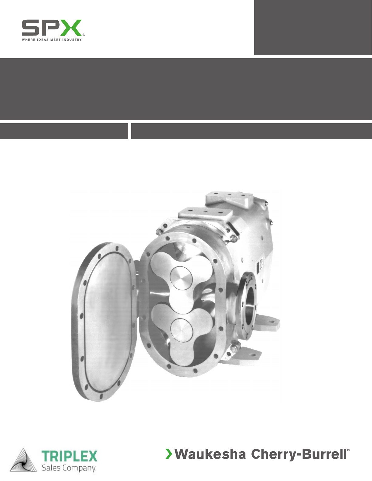
Introduction ........................................................ 6
Installation
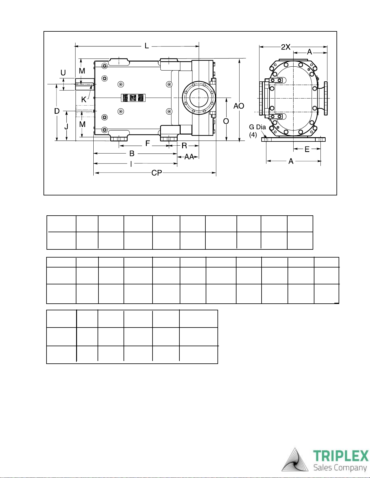
Basic Dimensions....................................... 7
Capacity ratings .......................................... 7
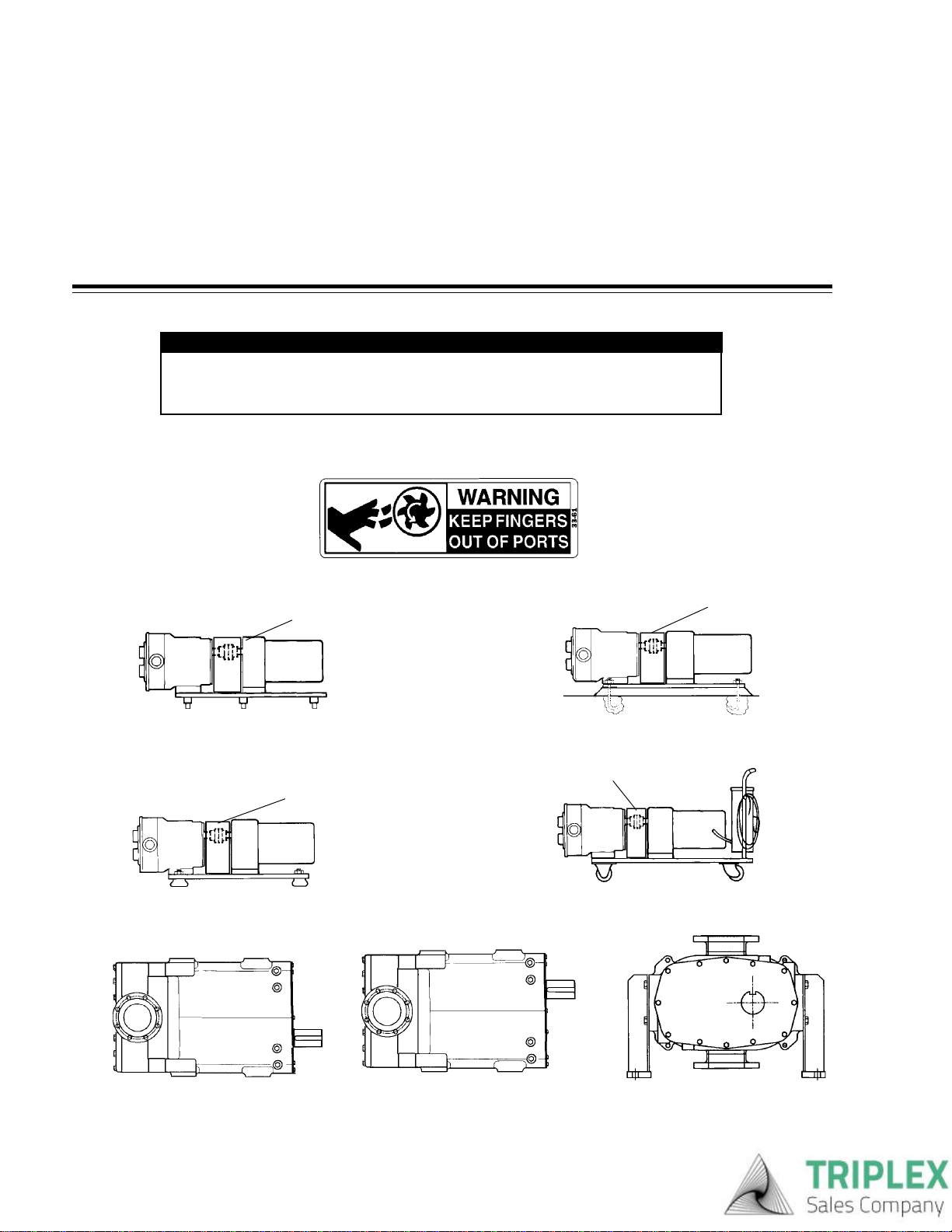
Pump and Drive Unit................................... 8
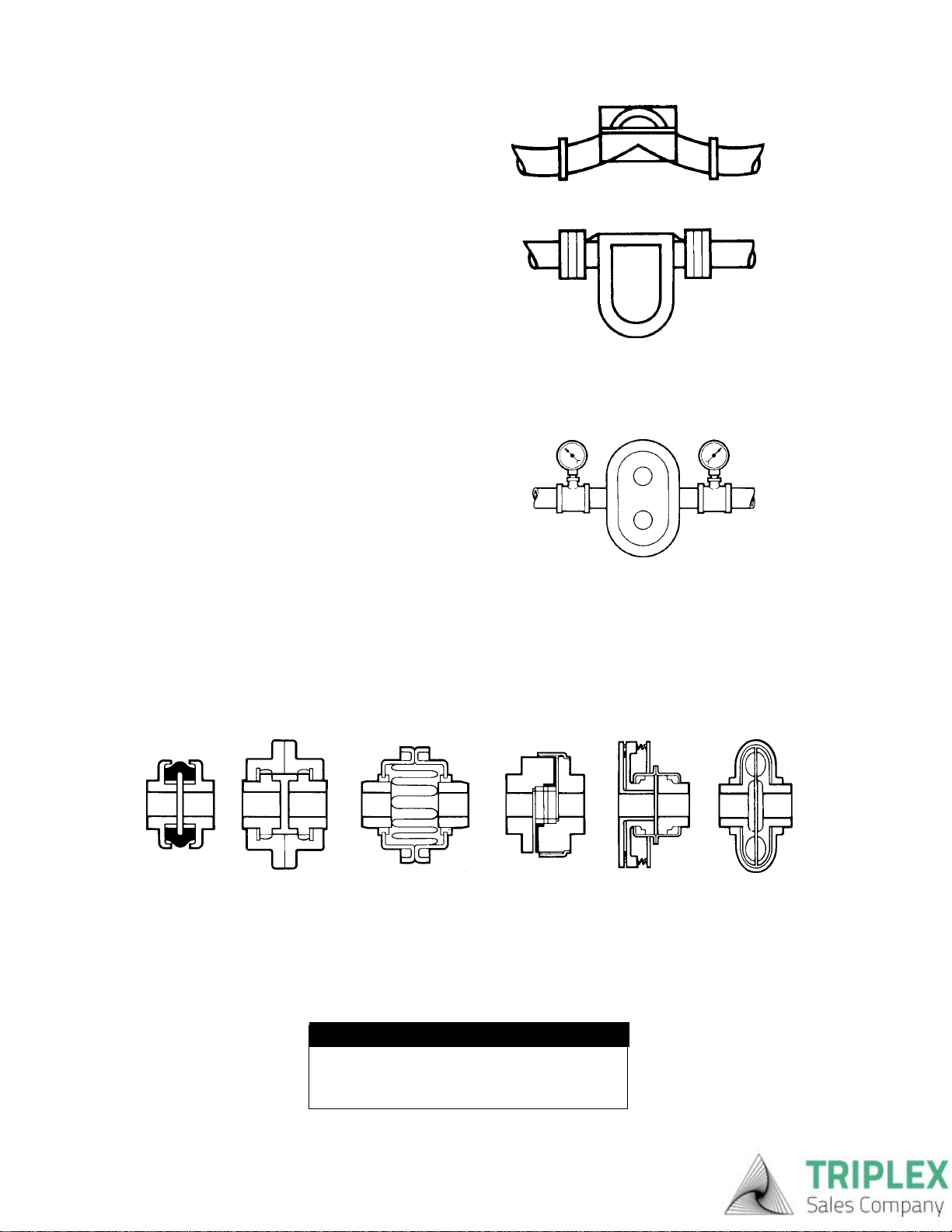
Piping Layout .............................................. 9
Valves ......................................................... 9
Strainers/Gages.......................................... 10
Alignment .................................................... 10-11
Pump Rotation ............................................ 11
Low Pressure Flush .................................... 12
High Pressure Flush ................................... 12
Start-up Check List ...................................... 13
Operation............................................................. 14
Lubrication.......................................................... 14
Cleaning .............................................................. 14
Troubleshooting a Pump System ... ............... 15-18
Maintenance
Safety Precautions ..................................... 19
Special Tools .............................................. 19
Disassembly Procedures
Fluid Head Removal ................................... 20
Cover Removal ........................................... 20
Rotor Removal ............................................ 21
Body Removal ............................................ 22
Mechanical Seal Removal ......................... 23
Gearcase Disassembly
... Timing Gears .......................................... 24
... Shaft and Bearing Removal................... 25
TABLE OF CONTENTS
Assembly Procedures
Shaft Sub Assembly..................................26
Bearings...................................................26
Shaft Installation in Gear Case Assembly 27-28
Timing Gear Installation..........................28
Adjusting Rotor to Body Backface .........29
Shims - All Models...............................................29
Fluid Head Assembly
Seal Assembly............................................30
Body Installation .................................................31
Rotor Installation.................................................31
Timing rotors ...............................................32
Cover Installation ................................................32
420/520 Gearcase Subassembly .......................33
Universal 420 Parts Listing................................34
Torque Specifications .......................34
Universal 520 Parts Listing................................35
Torque Specifications .......................35
SealsDouble Mechanical Seal.............................36
Single Inner Mechanical Seal.....................37
Single Outer Mechanical Seal....................38
Parts Ordering .....................................................39
Triplex Sales
1-847-839-8442
www.triplexsales.com

595-03034
FACTORYINSPECTION
EachWAUKESHApump isshipped completely assembled, lubricated andready foruse.
TheWAUKESHApump isa precision product, designed toprovide long,trouble-free service in a properly
designedsystem with normalmaintenance.
RECEIVING INSPECTION
Ports are rubber capped at the factory to keep out foreign objects. If covers are missing or damaged, a
thorough inspection of fluid head, by removing pump cover, is recommended. Be sure pumping head is clean
andfree of foreign material beforerotating shaft.
LOSSOR DAMAGE
If your pump has been lost or damaged in transit, file a claim at once with the delivering carrier and ask for an
Inspector to call. The carrier has signed the Bill of Lading acknowledging that the shipment has been received
fromus ingood condition.
We will of course assist you in every way in collecting claims for loss, or damage, however, we are not
responsible for the collection of claims or replacement of material.
WARRANTY
Please read the Warranty statement to correctly determine if you have a claim. In warranty claims you must
havea"Returned GoodsAuthorization"(RGA) from themanufacturer beforeany returns willbe accepted.Your
Distributorwill help youin awarranty problem. (Seeback pagesfor Information required)
WAUKESHA CHERRY-BURRELL WARRANTY
Sellerwarrantsitsproductstobefreefromdefectsinmaterialsandworkmanshipforaperiod
of one (1) year from the date of shipment. This warranty shall not apply to products which
requirerepairorreplacementduetonormalwearandtearortoproductswhicharesubjected
to accident, misuse or improper maintenance. This warranty extends only to the original
Buyer. Products manufactured by others but furnished by Seller are exempted from this
warrantyand are limitedto theoriginal manufacturer’s warranty.
Seller’s sole obligation under this warranty shall be to repair or replace any products that
Sellerdetermines,initsdiscretion,tobedefective.Sellerreservestherighteithertoinspect
the products in the field or to request their prepaid return to Seller. Seller shall not be
responsibleforanytransportationcharges,duty,taxes,freight,labororothercosts.Thecost
of removing and/or installing products which have been repaired or replaced shall be at
Buyer’sexpense.
Seller expressly disclaims all other warranties, express or implied, including without
limitation any warranty of merchantability of fitness for a particular purpose. The foregoing
setsforthSellersentireandexclusiveliability,andBuyer’exclusiveandsoleremedy,forany
claim of damages in connection with the sale of products. In no event shall Seller be liable
for any special consequential incidental or indirect damages (including without limitation
attorneys’ fees and expenses), nor shall Seller be liable for any loss of profit or material
arising out of or relating to the sale or operation of the products based on contract, tort
(including negligence), strict liability or otherwise.
RECEIVINGAND WARRANTY
Triplex Sales
1-847-839-8442
www.triplexsales.com

6 95-03034
INTRODUCTION
SanitationFeatures
•Rotor/shaft connection sealed from product zone.
•Sidemount capability for better draining.
•316L pump body standard.
•Exclusive, non-galling Waukesha “88” alloy rotors
standard; permits running at tighter clearances and
higher efficiencies; 316L stainless also available.
•Mechanical seals standard.
Long-lifefeatures
•Largediametershaftsinsealareaforgreaterstrength
and stiffness.
•Heavydutybearingframe (Gearcase)
•Double tapered roller bearings contribute further to
precise rotor movement and longer seal life.
•No bearing in product zone - accommodates severe
operatingconditions.
•Greaterflowcapacitythanconventionalhigh-volume
PDpumps.
•High pressure capability for more demanding jobs.
•Longer service life resulting from fresh engineering
approachandhighcapacitycomponents.
•Therightsealforeveryapplication,plusinterchange-
abilitywhenneeded.
•Metal rotor. exclusive Waukesha “88 “ non-galling
alloy, for close runningclearance.
*Mechanicalsealmaterial options.
•Carbon
• Ceramic
•Silicon Carbide
Installation/MaintenanceFlexibility
•Bi-directional flow. No flow direction specification
needed.
•4-Waymountingofgearcase,includingverticalalign-
ment of ports.
•External shimming simplifies shaft height adjust-
ments;reducesdowntime.
•Upperor Lower shaft position.
•High-volume capacity with the reliability of a
Waukesha
The Models 420 & 520 provide reliable and accurate pumping at high-volume capacities.
Displacement Nominal Maximum Maximum Temperature
Model Per Revolution Capacity Inlet/Outlet Pressure RPM Range
420-UHCL 1.83 Gal. 730 GPM 6" 300PSI 400 -40° F/C to
(6.93Liter) (166m3/hr.) (154.4mm) (20.7bar) 300°F/149°C.
520-UHCL 2.60 Gal 1040 GPM 8" 250PSI 400 -40°F/C to
(9.84Liter) (262m3/hr.) (203.2mm) (17.25bar) 300°F/149°C.
Triplex Sales
1-847-839-8442
www.triplexsales.com

795-03034
MODEL DIM. A AA AO B CP D E F
inch 21.00 7.22 27.25 22.00 46.47 18.75 9.00 16.50
420 mm 533.4 183.4 692,2 558.8 1180.3 476.2 228.6 419.1
520 inch 21.00 7.57 27.25 22.00 48.79 18.75 9.00 16.50
mm 533.4. 192.3 692.2 . 558.8 1239.3 476.2 228.6 419.1
MODEL DIM G I J K L M N O R
inch 1.06 33.60 9.75 1.00 40.81 8.50 6.04 14.25 9.97
420 mm 26.92 853.4 247.6 25.4 1036.6 215.9 153.4 362 253.2
520 inch 1.06 33.60 9.75 1.00 41.17 8.50 6.04 14.25 10.32
mm 26.92 853.4 247.6 25.4 1045.7 215.9 153.4 362 262.1
MODEL DIM U X 2X
inch 3.875 11.25 22.50
420 mm 98.42 285.7 571.5
520 inch 3.875 11.25 22.50
mm 98.42 285.7 571.5
INSTALLATION
UHCL BASIC DIMENSIONS
FLANGE
SIZE
ANSI 6”
154.4mm
ANSI 8 “
203.2mm
3-20-98
Triplex Sales
1-847-839-8442
www.triplexsales.com

8 95-03034
PUMPINSTALLATION
The installation of your Waukesha pump and its piping system should follow the practices described to give
optimumperformance, andbe inaccordance withlocal codesand restrictions.
All system equipment, such as motors, sheaves, drive couplings, speed reducers, etc., must be properly sized
to insure satisfactory operation of your Waukesha pump within its limits.
CAUTION: Waukesha pumpsare positivedisplacement, low slipdesign and willbe severely damagedif oper-
ated with closed valves in discharge or inlet lines. Pump warranty is not valid for damages caused by a hydrau-
lic overload from operation or start-up with a closed valve in the system.
WARNING
Fullcoupling guards must be installed to isolate operators and maintenance
personnelfromrotating components. Couplingguardsare provided with
Waukesha pumps as a part of a complete pump and drive package.
1. Installing the Pump and Drive Unit. Pumps of this type can be mounted on a common base plate with the
drive. The unit can be installed in several ways:
Leveling and/orvibrationisolation pads.Portable bases-formovement to different locations.
ManyCommercailtypes areavailable.
GUARD
GUARD
Adjustable leg base, commonly used for sanitary
pumps.Forwashdown under base.Can be easily
movedorrepositioned.
Permanent installationon foundationwith bolts and
grout.(Levelunit before grouting.)
GUARD GUARD
Bottom Shaft
Mount Sidemount
Vertical Fluid Entry
Top Shaft
Mount
INSTALLATION
Triplex Sales
1-847-839-8442
www.triplexsales.com

995-03034
A. Piping support:
Weightofpiping andfluid-supportpiping indepen-
dentlywith hangersor pedestals.
2.Good Piping Practice.
All piping to the pump should be supported independently, to minimize the forces exerted on the pump. Such
forces can cause misalignment of pump parts and lead to excessive wear of rotors, bearings and shafts.
NOTE: Pumpdimensionsand pump weights
areon page7.
INLET INLET
OUTLET
OUTLET
BY-PASS
FLOW
OUTLET
STANDARD SIDE MOUNT
CORRECT
AIR POCKET
UPRIGHT MOUNTING SHOWN
RELIEF
VALVE
INLET
VALVE VALVE
G.
F.
INCORRECT
OUTLET
OUTLET
INLET
A.
B.
C. INLET
D.
E.
.D
D. Inlet side-use check valves to keep inlet line full,
particularly with low viscosity fluids, and in start-stop
operation.
E. Inlet Vacuum Service-use check valve on outlet
side.
• Prevents backflow (air or fluid).
• Facilitates initial start-up (minimizes differential
pressure pump must supply to start flow).
F.''Isolation'' Valves-permitpumpmaintenanceand
removal safely and without emptying entire system.
Piping Layout
C. Inlet side: Slope piping up to inlet to avoid air
pocket.
CHECK
VALVE
CHECK
VALVE
WARNING
TO AVOID SERIOUS INJURY, DO NOT IN-
STALL OR SERVICE PUMP UNLESS
ALL POWER IS OFF AND LOCKED OUT.
INSTALLATION
Thermalexpansionof piping-cancausetremendous
forces. Use thermal expansion joints to minimize
forceson pump.
B. Flexible joints can also be used to limit the trans-
mission of mechanical vibration. Anchor free ends of
any flexible hose in system.
G. Relief Valve
Toprotect the pump and pipingsystem againstexces-
sive pressure, a relief valve should be installed. An
integral relief valve, designed to bypass the fluid inter-
nally from the pump outlet to the inlet, should not be
used on applications where the discharge must be
closedformorethanafewminutes.Prolongedoperation
ofthepumpwithcloseddischargewillcauseheatingof
thefluidcirculatingthroughthereliefvalve.Whensuch
operation is necessary, the relief valve, whether inte-
gral,attachable,orline-mounted,shoulddischargeex-
ternallythroughpipingconnectedtothefluidsource,or
if that is not practical, into the inlet piping near the
source.
Triplex Sales
1-847-839-8442
www.triplexsales.com

10 95-03034
WARNING
TO AVOID SERIOUS INJURY, DO NOT
INSTALL OR SERVICE PUMP UNLESS
ALL POWER IS OFF AND LOCKED OUT.
Inlet Side-Strainers and Traps.
Inlet side strainers and traps can be used to prevent
pumpdamage fromforeign matter.Selection must be
carefully made as clogging can easily occur, restricting
the inlet, causing cavitation and flow stoppage.
PressureGauges
Pressureand Vacuum gauges providethe easiestway
totell yousomething about the pump operation.
•Normal or abnormalpressures
•Overload conditions
• Indication of flow
•Changes inpump condition
• Changes in system conditions
• Changes in fluid viscosity
MAGNETIC TRAP
3. Alignment of Pump to Drive.
Pumps and drives which are ordered from the factory
and mounted on a common base plate are accurately
alignedbeforeshipment.Thealignment should be
rechecked after the complete unit has been installed
andthe piping completed.Periodic recheckingis
advisableduring thepump service life.
STRAINER
In-line Drives. For initial pump installation, and for rechecking alignment, the following steps are
advised:
Use a flexible coupling to connect the drive to the pump. Many different types are available, including cou-
plingswith slipor overload provision.
Aflexible coupling is used to compensate for end play and small differences in alignment. The
pump and drive shaft should be aligned as closely as is possible.
FLUID
SLIP
OVERLOAD
DETENT
FLEXIBLE
MEMBER
GEAR
TYPE
RUBBER
CUSHIONED
INSTALLATION
Triplex Sales
1-847-839-8442
www.triplexsales.com

1195-03034
Aligning belt and chain drives. Using straight-edges and visual check:
Checkangular alignment:
Using feeler gauges, or taper gauges, adjust to get
equal dimension at all points. At the same time set
spacebetween couplinghalves to manufacturer’s
recommendeddistance.
FEELER OR TAPER GAUGE
SHIM AS
NEEDED
SHIM HEIGHT AS
NEEDED
MOVE DRIVE
AS NEEDED
Check parallel misalignment: Use straight edges and shims:
After piping is complete, and drive and couplings are aligned, turn pump shaft manually
to see if it turns freely without binding.
Check rotation direction of drive to see that pump will rotate in proper direction.
(“LiquidEnd” of pumpisshown below.)
WarningNote:Covershavebeenremovedforillustrationpurposesonly.
Thepumpcannotbeoperatedwiththecoverremoved.
TOP SHAFT
DRIVE
DETERMINE ROTATION DIRECTION BY LOOKINGAT THE MOTOR COUPLING.
TOP SHAFT
DRIVE
LOWER SHAFT
DRIVE
LOWER SHAFT
DRIVE
Figure1
VERTICAL
POSITION
SHOWN
INSTALLATION
KEEP DISTANCE
TO MINIMUM
After piping is complete and before belts are installed, turn pump shaft manually to see that it turns
freely. Check rotation direction of pump to see that pump will rotate in proper direction (see figure 1)
Install belts and tension them correctly. Install belt guard.
MOVE DRIVE TO CORRECT ANGULAR
AND PARALLEL MISALIGNMENT.
Triplex Sales
1-847-839-8442
www.triplexsales.com

12 95-03034
INSTALLATION
LOW PRESSURE FLUSH
(STANDARD RECOMMENDATION)
a. Set flow rate of approximately 1/4 GPM for most
applications.Forhigh temperature applications,
increaseflow.
b. Flushing media is restricted on inlet side and
has free flow to drain on outlet side.
HIGH PRESSURE FLUSH
This method is good for abrasive applications
and products that tend to "set" on seal faces.
a. Set flow rate of approximately 1/4 GPM for
mostapplications.
Solenoidis recommended to stop flushing
whenpump is stopped.Restriction andpres-
suregauge isat discharge end. Do not exceed
30 PSI with standard seals.
RESTRICTOR
PRESSURE GAUGE
HIGH PRESSURE
LOW PRESSURE
Triplex Sales
1-847-839-8442
www.triplexsales.com

1395-03034
START-UPCHECKLIST
The Waukesha Pump is a positive displacement pump and thus can develop very high pressures.
To protect lines, equipment and personnel, certain precautions must be taken.
1. Review page 9, particularly "Relief Valves". Install relief valves if needed.
2. Check that piping and pump are clean and free of foreign material, such as welding slag,
gaskets, etc. Do not use pump to flush system.
3. See that all piping connections are tight and leak-free. Where possible, check system with
“non-hazardous”fluid.
4. Check to see that pump and drive are lubricated. See page 14. Check Drive
LubricationInstruction.
5. Check that all guards are in place and secure.
6Seals: Double mechanicaland double O-ringseals withflushingrequire adequatesupply and
flow of clean flushing fluids.
7. See that all valves are open on discharge system, and that free flow path is open to
destination.
8. See that all valves are open on inlet side, and that fluid can reach pump.
9.Check directionof pump anddrive rotation.(See page 11)
10. Start pump drive. Where possible, start at slow speed, or jog.
Check to see that liquid is reaching pump within several minutes. If pumping does not begin and stabilize,
checkitems under“No Flow” or “InsufficientFlow” on(Page 15)
Troubleshooting a Pumping System.
Triplex Sales
1-847-839-8442
www.triplexsales.com

14 95-03034
LUBRICATION
Thegears are factorylubricated withMicro-PlateNo.
140 oil at the quantity shown for top or bottom shaft
mounts. If you mount your pump other than top or
bottom shaft drive, check oil level.
Thebearings are factorygreased withMicro-Plate
#555grease.
Change oil every 500 hours. If pump is installed
wheremoisture and condensationareheavy,change
oilmorefrequently.
Bearings must be greased every 250 hours or less
dependingonmoisture and condensationconditions.
NOTE:Forhot or coldextremes use appropriate
lubricant as shown in the following tables.
OIL
Micro-Plate#140
-10°to 350° F. (-23° to 177°C.)
GREASE
OILCAPACITY(GEARS)
SHAFT
MODEL TOP OR SIDE
BOTTOM MOUNT
420/520 3.0 Quart (3.4 Liter) 4.7 Quart (4.5 Liter)
Silicone -20° to 5° F.( -29° to 15° C.)
Micro-Plate#555 (5° to350° F.(-15° to177° C.)
Normaloperation covers aspeedrange of0-600RPM and pressurerange of 0-200PSI.Temperature range with
standardrotorsis -40°to 200° F. and with hotclearance rotors,180° to 300° F.(For operationat higher tempera-
tures,consultWaukeshaCherry-Burrell.)
SeeSTART-UPCHECK LIST(Page13) andTROUBLESHOOTING(Page 15-18) for additionaloperationinforma-
tion.
CLEANING
ThestandardWaukeshapumpswithoutCIPproper-
ties, are designed to be completely disassembled for
thoroughand easy cleaning.
Clean the pump every day or at the end of a process.
Disassemblethe fluidhead as outlined.Remove and
clean the cover O-ring, pump seals and rotor nut
assembly. Inspect and replace O-rings if required.
NOTE:
Where possibility of material "setting up" during shut
down exists, flushing with solvent or dis-assembly of
fluidheadand manual cleaning arerequired.
OILLEVEL
OILFILL
TOP SHAFT DRIVE
OILFILL
BOTTOM SHAFT DRIVE
OILLEVEL
BEARING GREASE
FITTINGS(4)
MOUNTINGPOSITIONS
A
CSIDEMOUNT DRIVE
DRIVELUBRICATION
Referto drive manufacturer'smanual shipped with
unit.
B
DRAIN
DRAIN
OPERATION
OILFILL
TOP SIDE
OIL
LEVEL OIL DRAIN
11-24-98
Triplex Sales
1-847-839-8442
www.triplexsales.com

1595-03034
WARNING
TO AVOID SERIOUS INJURY, DO NOT
INSTALL OR SERVICE PUMP UNLESS
ALL POWER IS OFF AND LOCKED OUT.
WARNING
TO AVOID POSSIBLE SERIOUS INJURY,
SHUT OFF AND DRAIN PRODUCT FROM
PUMP PRIOR TO DISCONNECTING PIPING.
No flow, pump Drive motor not running Check resets, fuses, circuit
not turning breakers
Keys sheared or missing Replace
Drive belts, power transmission Replace or adjust
components slipping or broken
Pump shaft, keys, or gears Inspect: replace parts
sheared
No flow, pump Valve closed in inlet line Open valve
not priming
Inlet line clogged or restricted Clear line, clean filters, etc.
Air leaks due to bad seals or pipe Replace seals; check lines for
connections leakage (can be done by air
pressure or by filling with liquid
and pressurizing with air)
Pump speed too slow Increase speed. Filling inlet lines
with fluid may allow initial
start-up. Foot valve may solve
start-up problems permanently.
Liquid drains or siphons from Use foot valve or check valves
system during off periods
TROUBLESHOOTINGAPUMPING SYSTEM
Once a pump is properly selected and installed in a system, operation should be trouble free. However, in
existing systems, or as pump and system conditions change, problems may develop. Following are some
troubleshootinghints tohelp identify and solve problems.
Problem ProbableCauses Solutions
Triplex Sales
1-847-839-8442
www.triplexsales.com

16 95-03034
Problem Probable Causes Solutions
No flow, pump "Air" lock. Fluids which "gas off", Manual or automatic air bleed from
not priming or vaporize, or allow gas to come pump or lines near pump
out of solution during off periods
Extra clearance rotors, worn pump Increase pump speed, use foot
valve to improve priming
Net inlet pressure available too low Check NIPA, NIPR~, recalculate
system. Change inlet system as
needed.
On "Vacuum'' inlet system: On Install check valve in discharge line
initial start-up, atmospheric "blow
back'' prevents pump from
developing enough differential
pressure to start flow.
Insufficient flow Speed too low to obtain Check flow-speed curve
desired flow
Air leak due to bad seals or Replace seals, check inlet fittings.
pipe connections
Fluid vaporization Strainers, foot valves, inlet fittings Clear lines. If problem continues,
("starved'' pump inlet) or lines clogged inlet system may require change
Inlet line size too small, inlet line Increase inlet line size. Reduce length,
too long. Too many fittings minimize direction and size changes,
or valves. Foot valve, strainers reduce number of fittings.
too small .
NIPA too low Raise liquid level in source tank
NIPA too low Increase by raising or pressurizing
source tank
NIPA - Net Inlet Pressure Available at Pump
NIPR - Net Inlet Pressure Required by Pump
TROUBLESHOOTING
Triplex Sales
1-847-839-8442
www.triplexsales.com

1795-03034
Problem Probable Causes Solutions
Fluid vaporization NIPA too Low Select larger pump size with
(''starved'' pump inlet) smaller NIPR
Fluid viscosity greater Reduce pump speed and accept
than expected lower flow, or change system to
reduce line losses.
Fluid temperature higher than Reduce temperature, reduce speed
expected (vapor pressure higher) and accept lower flow or change
system to increase NIPA
Insufficient flow. Fluid Flow diverted in branch line, open Check system and controls
being bypassed valve,etc.
somewhere
Insufficient flow. Hot (HC) or extra clearance rotors Replace with standard clearance
High slip on '"cold'' fluid, and/or low rotors
viscosity fluid
Worn pump Increase pump speed (within limits).
Replace rotors, recondition pump.
High pressure Reduce pressure by system changes
Noisy operation Cavitation
High fluid viscosity, Slow down pump, reduce
High vapor pressure fluids, temperature, change system
High temperature
NIPA less than NIPR To increase NIPA or reduce NIPR,
see Engineering Manual
Air or gas in fluid
Leaks in pump or piping Correct leaks
Dissolved gas or naturally Minimize discharge pressure. Also
aerated products see "Cavitation'' above.
•Mechanical noises
Rotor to body contact
Improper assembly Check clearance with shims.
See page 29.
TROUBLESHOOTING
Triplex Sales
1-847-839-8442
www.triplexsales.com

18 95-03034
TROUBLESHOOTING
Problem Probable Causes Solutions
Noisy operation • Rotor to body contact
Distortion of pump due to Reassemble pump or reinstall
improper piping installation. piping to assure free running
Pressure higher than rated Reduce pressure if possible
Worn bearing Rebuild with new bearings.
Lubricate regularly
Worn gears Rebuild with new gears. Lubricate
regularly
Rotor to rotor contact
Loose or mis-timed gears. twisted Rebuild with new parts
shaft, sheared keys. worn splines
• Drive component noise-gear Repair or replace drive train
trains, chains, couplings,
bearings.
Pump requires • Higher viscous losses than If within pump rating, increase drive
excessive power expected size
(overheats, stalls.
high current draw,
breakers trip) • Higher pressure than Reduce pump speed, increase
expected line sizes
• Fluid characteristics
Fluid colder than expected. Heat fluid. insulate or heat trace
viscosity high lines. Use pump with more running
clearances.
Fluid sets up in line and pump Insulate or heat trace line.
during shut down Install "soft start" drive.
Install recirculating bypass system.
Flush with other fluid.
Fluid builds up on pump surfaces Use pump with more running
(example. latex, chocolate. clearance
fondants)
''Short'' pump High corrosion rate Upgrade material of pump
service life Pumping abrasives Larger pumps at slower speeds,
can help
Speeds and pressures higher Reduce speeds and pressures by
than rated changes in system
Worn bearings and gears due to Set up and follow regular
lack of lubrication lubrication schedule
Misalignment of drive and piping. Check alignment of piping. Check
Excessive overhung load or drive alignment and loads. (Page 11)
misaligned couplings.
Triplex Sales
1-847-839-8442
www.triplexsales.com

1995-03034
Because all pump parts are
extremelyheavy,appropriate
lifting equipment is required.
FLUIDHEADDISASSEMBLY
RECOMMENDED SAFETY PRECAUTIONS
• Completely flush all product and cleaning solutions from the pump fluid head before any component removal is
started.
• Lock out, or disconnect all power sources to the pump drive motor before starting any work.
• Drain and (or) close off all inlet and discharge piping before disconnecting piping from fluid head.
SPECIAL TOOLS
Special tools are required to aid in the disassembly and
reassembly of the fluid head.. These tools are as
follows:
420/520UL TOOL KIT #107361
Part No. Description Qty
30-360 Eyebolt 1/2-13 x .75" ZP 2
103985 Guide Bolt 3/4-10 X 11” 2
107364 Seal Preload Tool 1
107362 Torque Wrench Kit 1
(Contents of Torque Wrench Kit)
420/520UL TORQUE WRENCH KIT #107362
Part No. Description Qty
101640 1/2” Drive Torque Wrench 1
101645 1/2” Drive Socket, 1-1/8” 1
101643 1/2” Drive Socket, 3/4” 1
107363 Drive Bit 12mm 1
• 1000 pound capacity hoist and suitable
lifting straps or chains.
• Two(2) 1/2-13x1”long bolts.
WARNING
WARNING
DO NOT OPERATE
WITHOUT GUARD IN PLACE
WARNING
TO AVOID POSSIBLE SERIOUS INJURY,
SHUT OFF AND DRAIN PRODUCT FROM
PUMP PRIOR TO DISCONNECTING PIPING.
MAINTENANCE
Triplex Sales
1-847-839-8442
www.triplexsales.com

20 95-03034
FLUIDHEAD COVERREMOVAL
NOTE: THEFLUIDHEAD COVER WEIGHS
APPROXIMATELY 200 POUNDS. LIFTING EQUIPMENT IS REQUIRED.
1. Install an eye bolt into the tapped hole at the top of the cover ( or at both ends if the pump is side mounted.).
2. Position the hoist over the fluid head and attach it to the eye bolt(s) on the cover. Apply light lifting load to
the cover.
3. Remove the cover bolts.
4. Swiing the cover partially open.
5. Remove the hinge pin setscrews and hinge pins.
6. Supporting the cover with the hoist, remove the cover from the fluid head.
7. Clean and inspect the cover, O-ring, and all bolts for signs of wear or damage. Repair or replace any ques-
tionablecomponent.
COVER REMOVAL
Because all pump parts are
extremelyheavy,appropriate
lifting equipment is required.
WARNING
MAINTENANCE
EYE BOLT
SETSCREW
HINGE PIN
5.
Triplex Sales
1-847-839-8442
www.triplexsales.com
Table of contents