Blumfeldt Liquidflow 800 User manual

Liquidow 800
Liquidow 1200 INOX Pro
Hauswasserwerk / Gartenpumpe
Domestic Waterworks for Homte and Garden
Aqueduc domestique pour la maison et le jardin
Bomba de agua para el hogar y jardín
Impianto idrico domestico/pompa da giardino
10034756 10034757


3
DE
English 9
Français 15
Español 21
Italiano 27
Sicherheitshinweise 4
Benutzung 6
Hinweise zur Entsorgung 8
Konformitätserlärung 8
Sehr geehrter Kunde,
wir gratulieren Ihnen zum Erwerb Ihres Gerätes. Lesen
Sie die folgenden Hinweise sorgfältig durch und befolgen
Sie diese, um möglichen Schäden vorzubeugen. Für
Schäden, die durch Missachtung der Hinweise und
unsachgemäßen Gebrauch entstehen, übernehmen wir
keine Haftung. Scannen Sie den QR-Code, um Zugriff
auf die aktuellste Bedienungsanleitung und weitere
Informationen rund um das Produkt zu erhalten.
TECHNISCHE DATEN
Artikelnummer 10034756 10034757
Stromversorgung 230 V ~ 50 Hz
Leistung
Qmax 3,2 m3/h 3,7 m3/h
Hmax 40 m 46 m
Betriebsdruck 1,5 - 3 bar 1,5 - 3 bar
IP-Schutzart x4 x4
Dba <88 mm <88 mm
Rohrdurchmesser 1 Zoll 1 Zoll
INHALT

4
DE
SICHERHEITSHINWEISE
Das Gerät ist für sauberes Wasser mit einer Temperatur von max. 50°C
ausgelegt: ein anderweitiger Einsatz sollte vermieden werden.
Bei Erreichen des maximalen Pumpendrucks schaltet das Aggregat die Pumpe
aus. Es muss jedoch mindestens ein Druckunterschied zwischen Ein- und
Ausschalten von 1,4 bar bestehen.
Kinder ab 8 Jahren, psychisch, sensorisch und körperlich eingeschränkte
Menschen dürfen das Gerät nur benutzen, wenn sie vorher von einer für
sie verantwortlichen Aufsichtsperson ausführlich mit den Funktionen und
den Sicherheitsvorkehrungen vertraut gemacht wurden und die damit
verbundenen Risiken verstehen.
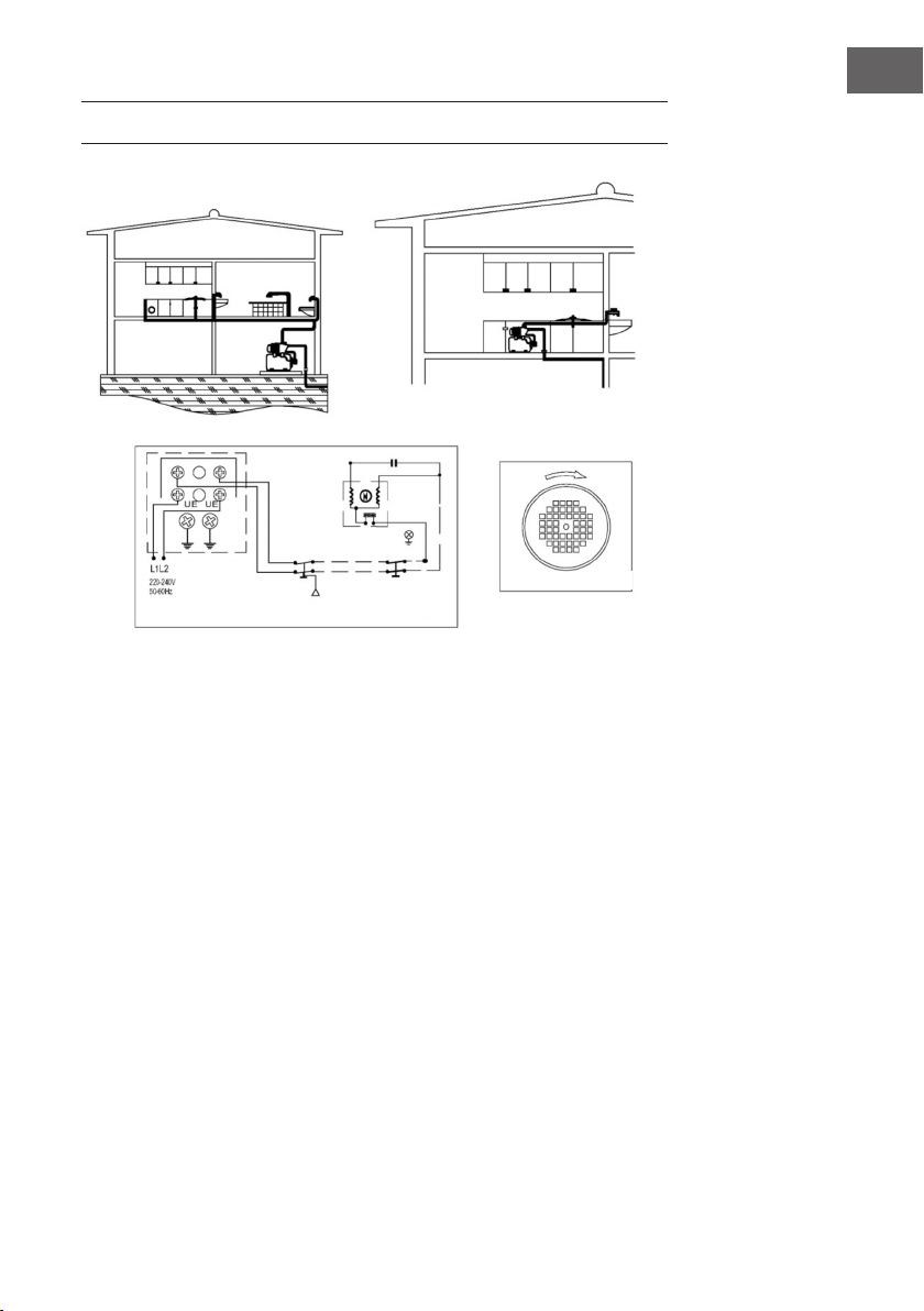
Montage
• Stellen sie sicher, dass die Anlage überschwemmungssicher aufgestellt
und ausreichend mit trockener Luft gekühlt wird.
• Ist die Pumpe direkt im Verteilernetz montiert, so muss beachtet
werden, dass der Vordruck sich mit dem Pumpendruck addiert und der
Gesamtdruck nicht über 10 bar liegen darf.
• Das Aggregat kann in eine bestehende Leitung / Anlage montiert werden,
sofern der minimale Wasserbedarf der Pumpe immer gedeckt ist.
Beachten Sie die Montageschemas.
Netzanschluss
• Die Stromaufnahme der Pumpe darf nicht über 10 A und die maximale
Leistung des Motors nicht über 1,8 kW liegen. In der Elektroinstallation
ist eine Trennvorrichtung vorzusehen, die das Abtrennen vom Netz
mit mindestens 3 mm Kontaktöffnung für jeden Pol zulässt. Pumpen in
Wechselstromausführung haben einen integrierten Motorschutzschalter.
Pumpen in Drehstromausführung sind bauseitig mit einem eingestellten
Motorschutzschalter zu installieren. Für die Folgen unsachgemäßer
Installation, Inbetriebnahme und nicht vorschriftsgemäßer
Elektroinstallation übernehmen wir keine Haftung.
• Das Netzkabel muss dem Typ H08 RN-F nach DIN VDE 0620 entsprechen.
• Da Schema erleichtert einen korrekten Netzanschluss.
• Das System wird durch einen Differentialschalter gesichert (1 fn=30 mA)
• Das Netzkabel der Pumpe muss mindestens H07 RN-R nach DIN VDE
0620 entsprechen und mit Kabelschuhen versehen sein. Das Anschließen
der der Pumpe muss durch einen Elektrofachmann erfolgen.

5
DE
ANSCHLUSSSCHEMA
Bild 1
Bild 2
Bild 3

6
DE
BENUTZUNG
Kontrollmaßnahmen vor der ersten Inbetriebnahme
1. Stellen Sie sicher, dass Spannung und Frequenz von Stromnetz und
Aggregat (siehe Typenschild) übereinstimmen.
2. Achten Sie auf ein freies Drehen der Pumpenwelle.
3. Füllen Sie durch Aufschrauben des entsprechenden Füllverschlusses den
Pumpenkörper sowie die Ansaugleitung mit Wasser.
4. Setzen Sie die Pumpen niemals trocken in Betrieb.
Inbetriebnahme
1. Öffnen Sie alle eventuell vorhandenen Schieberventile in Druck- und
Ansaugleitung.
2. Stellen Sie den Hauptschalter auf EIN. Die Pumpe startet sofort.
Während der ersten Inbetriebnahme muss ein Wasserhahn geöffnet
sein, damit sich die ganze Anlage entlüften kann. Sobald alle
Wasserhähne geschlossen sind, erreicht die Pumpe ihren maximalen
Druck und das Aggregat schaltet automatisch ab.
3. Überprüfen, ob der Motor im Uhrzeigersinn dreht (Blickrichtung auf die
Lüfterhaube, siehe Bild 2).
4. Funktioniert danach die Anlage nicht ordnungsgemäß, sollte die die
nachfolgende Aufstellung eventueller Defekte zu Rate gezogen werden.
Wartung
Die Pumpe bedarf keiner besonderen Wartung. Während der kalten
Jahreszeit und bei längerem Stillstand der Anlage muss der Pumpenkörper
und das KIT entleert werden. Wird die Anlage für längere Zeit überhaupt
nicht benutzt, müssen Sie die Pumpe und das KIT reinigen und an einem
trockenen und gut gelüfteten Ort lagern.

7
DE
FEHLERBEHEBUNG
Problem Ursache Lösung
Die Anlage schaltet
sich nicht ab.
Leckage an einem Hahn
oder Schwimmerventil
Hahn oder Schwimmer-
ventil abdichten.
Lufteintritt Rohrverbindungen und
Dichtungen überprüfen.
Leckage in der Druck-
leitung. Druckleitung abdichten.
Der Motor funkti-
niert, bringt jedoch
keine Leistung.
Ein Absperrventil ist
geschlossen. Das Ventil öffnen.
Lufteintritt Rohrverbindungen und
Dichtungen überprüfen.
Ungenügender
Wasserdruck.
Gesamtförderdruck
Förderhöhe und
Druckeverluste über-
prüfen.
Lufteintritt Rohrverbindungen und
Dichtungen überprüfen.
Leckage in der Druck-
leitung. Druckleitung abdichten.
Die Anlage schaltet
sich dauernd ein
und aus.
Leckage an einem Hahn
oder Schwimmerventil
Hahn oder Schwimmer-
ventil abdichten.
Die Anlage schaltet
sich nicht ein.
Pumpe ist blockiert. Kundendienst kontak-
tieren.
Keine Spannung vor-
handen.
Sicherungen kontrol-
lieren.
Die Wassersäule ist
höher als der Aggregat-
Anlaufddruck.
Grundeinstellung des
Aggregats berücksich-
tigen.

8
DE
HINWEISE ZUR ENTSORGUNG
Bendet sich die linke Abbildung (durchgestrichene
Mülltonne auf Rädern) auf dem Produkt, gilt die
Europäische Richtlinie 2012/19/EU. Diese Produkte
dürfen nicht mit dem normalen Hausmüll entsorgt
werden. Informieren Sie sich über die örtlichen
Regelungen zur getrennten Sammlung elektrischer und
elektronischer Gerätschaften. Richten Sie sich nach
den örtlichen Regelungen und entsorgen Sie Altgeräte
nicht über den Hausmüll. Durch die regelkonforme
Entsorgung der Altgeräte werden Umwelt und
die Gesundheit ihrer Mitmenschen vor möglichen
negativen Konsequenzen geschützt. Materialrecycling
hilft, den Verbrauch von Rohstoffen zu verringern.
KONFORMITÄTSERLÄRUNG
Hersteller: Chal-Tec GmbH, Wallstraße 16,
10179 Berlin.
Dieses Produkt entspricht den folgenden Europäischen
Richtlinien:
2011/65/EU (RoHS)
2014/30/EU (EMV)
2014/35/EU (LVD)

9
EN
Safety Instructions 10
Use 12
Disposal Considerations 14
Declaration of conformity 14
Dear Customer,
Congratulations on purchasing this equipment. Please
read this manual carefully and take care of the following
hints to avoid damages. Any failure caused by ignoring
the items and cautions mentioned in the instruction
manual are not covered by our warranty and any liability.
Scan the QR code to get access to the latest user manual
and other information about the product.
TECHNICAL DATA
Item number 10034756 10034757
Power supply 220-240 V ~ 50/60 Hz
Power
Qmax 3.2 m3/h 3.7 m3/h
Hmax 35 m 44 m
Work pressure 1.5 - 3 bar 1.5 - 3 bar
IP protection class x4 x4
Dba <88 mm <88 mm
Diameter of pipe 1" 1"
CONTENTS

10
EN
SAFETY INSTRUCTIONS
The appliance is designed for clean water with a temperature of max. 50°C:
any other use should be avoided.
When the maximum pump pressure is reached, the unit switches off the pump.
However, there must be a pressure difference of at least 1.4 bar between
switching on and off.
Children from the age of 8 years, people with mental, sensory or physical
impairments may only use the unit if they have been thoroughly familiarised
with the functions and safety precautions by a responsible supervisor and
understand the risks involved.
Assembly
• Make sure that the system is installed ood-proof and sufciently cooled
with dry air.
• If the pump is mounted directly in the distribution network, it must be
ensured that the inlet pressure is added to the pump pressure and that the
total pressure does not exceed 10 bar.
• The unit can be installed in an existing pipe / plant, provided that the
minimum water requirement of the pump is always covered. Observe the
installation diagrams.
Electrical connection
• Nominal current consumption of the pump must not exceed 10 (A) and the
maximum power of the motor must not exceed 1.8 kW. A disconnecting
device must be provided in the electrical installation, which allows
disconnection from the mains with at least 3 mm contact opening for
each pole. Pumps in alternating current design have an integrated motor
protection switch. Pumps in three-phase design must be installed by
the customer with an adjusted motor protection switch. We accept no
liability for the consequences of improper installation, commissioning and
improper electrical installation.
The power cable must correspond to type H08 RN-F according to DIN
VDE0620.
• This diagram facilitates a correct mains connection.
• The system is secured by a differential switch (1 fn=30 mA)
• The power cable of the pump must at least correspond to H07 RN-R
according to DIN VDE 0620 and be provided with cable lugs. The
connection of the pump must be carried out by a qualied electrician.

11
EN
CONNECTION SCHEME

12
EN
USE
Controls prior to start up
Before st starting ensure
• that the grid voltage and frequency match those featured on the
specicaton plate.
• that the pump shaft turns freely.
• that te pump body is completely full of water-ll by unscrewing the
corresponding priming plug.
The pump .should never be operated dry.
Start-up
1. Open all gate valves in the suction and discharge lines.
2. Switch on the power and the pump will start automatically. Öffnen Sie
alle eventuell vorhandenen Schieberventile in Druck- und Ansaugleitung.
3. Stellen Sie den Hauptschalter auf EIN. Die Pumpe startet sofort. While
doing so, leave the discharge tap open to bleed any air there may be in
the system. Then close the tap and the assembly will shut down when it
reaches masimum pump pressure.
4. Verify the motor sense of rotating is clockwise, checked from the fan
cover (g 2).
5. If the assembly does not opeate, does not pruduce pressure or does
not shut down, try to discover the cause of the problem consulting the
troubleshooting guide provided below.
Maintenance
The unit does not require any specic maintenance. Notwithstandig, we
recommend that thery be emptied when temperatures are low and there is a
risk of freezing or if the unit is not to be used for a long period of time. If the
unit is not to be used for a very long period, it must be cleaned and stored in a
dry, well-ventilated space.

13
EN
TROUBLESHOOTING
Problem Cause Solution
The unit does not
shut down
Tap or cistern leak. Repair leak.
Air entering suction
channel.
Carefully seal all joints
and connectors.
Leak in discharge pipe-
work. Repair leak.
The motor oper-
ates but provides
no ow.
Closed gate valve. Open valve.
Air entering suction
channel.
Carefully seal all joints
and connectors.
The pressure is not
sufcient.
Total head height. Check geometric height
plus loss of head.
Air entering suction
channel.
Carefully seal all joints
and connectors.
Leak in discharge pipe-
work. Repair leak.
The unit is con-
stantly stopping
and starting.
Tap or cistern leak. Repair leak.
The unit does not
start.
Plump block. Call service agent.
No power. Check fuses.
The static head is
greater than the assem-
bly start pressure.
Check start-up setting is
correct.

14
EN
DISPOSAL CONSIDERATIONS
According to the European waste regulation
2012/19/EU this symbol on the product or on its
packaging indicates that this product may not be
treated as household waste. Instead it should be taken
to the appropriate collection point for the recycling of
electrical and electronic equipment. By ensuring this
product is disposed of correctly, you will help prevent
potential negative consequences for the environment
and human health, which could otherwise be caused by
inappropriate waste handling of this product. For more
detailed information about recycling of this product,
please contact your local council or your household
waste disposal service.
DECLARATION OF CONFORMITY
Producer: Chal-Tec GmbH, Wallstraße 16,
10179 Berlin.
This product is conform to the following European
Directives:
2011/65/EU (RoHS)
2014/30/EU (EMC)
2014/35/EU (LVD)

15
FR
Consignes de sécurité 16
Utilisation 18
Informations sur le recyclage 20
Déclaration de conformité 20
Chère cliente, cher client,
Toutes nos félicitations pour l’acquisition de ce nouvel
appareil. Veuillez lire attentivement et respecter
les instructions de ce mode d’emploi an d’éviter
d’éventuels dommages. Nous ne saurions être tenus
pour responsables des dommages dus au non-respect
des consignes et à la mauvaise utilisation de l’appareil.
Scannez le QR-Code pour obtenir la dernière version
du mode d'emploi ainsi que d'autres informations
concernant le produit.
FICHE TECHNIQUE
Numéro d'article 10034756 10034757
Alimentation 230 V ~ 50 Hz
Puissance
D max 3,2 m3/h 3,7 m3/h
H max 40 m 46 m
Pression de
fonctionnement
1,5 - 3 bar 1,5 - 3 bar
Norme IP x4 x4
Dba <88 mm <88 mm
Diamètre de tuyau 1 pouce 1 pouce
SOMMAIRE

16
FR
CONSIGNES DE SÉCURITÉ
L'appareil est destiné à être utilisé avec de l'eau propre à une température de
max. 50 °C : toute autre utilisation doit être évitée.
Lorsque la pression maximale de la pompe est atteinte, l'unité arrête la pompe.
Cependant, il doit y avoir au moins une différence de pression de 1,4 bar entre
la mise en marche et l'arrêt.
Les enfants à partir de 8 ans, personnes aux capacités mentales, physiques et
psychiques réduites ne doivent utiliser l'appareil que s'ils ont été familiarisés
en détail avec les fonctions et les consignes de sécurité par une personne
responsable de leur sécurité et s'ils comprennent les risques associés.
Montage
• Assurez-vous que le système est protégé contre les inondations et qu'il est
correctement refroidi à l'air sec.
• Si la pompe est installée directement dans le réseau de distribution,
assurez-vous que la pression d'admission est ajoutée à la pression de la
pompe et que la pression totale ne dépasse pas 10 bars.
• L'unité peut être installée dans une ligne / un système existant, à condition
que les besoins en eau minimum de la pompe soient toujours couverts.
Suivez les schémas de montage.
Branchement au secteur
• La consommation de courant de la pompe ne doit pas dépasser 10 A et la
puissance maximale du moteur ne doit pas dépasser 1,8 kW. Un dispositif
de déconnexion doit être prévu dans l'installation électrique qui permet la
déconnexion du secteur avec une ouverture de contact d'au moins 3 mm
pour chaque pôle. Les pompes à courant alternatif ont un interrupteur de
protection moteur intégré.
• Les pompes triphasées doivent être installées par le client avec
un interrupteur de protection moteur réglé. Nous déclinons toute
responsabilité pour les conséquences d'une mauvaise installation, mise en
service et mauvaise installation électrique.
• Le cordon d'alimentation doit correspondre au type H08 RN-F selon DIN
VDE 0620.
• Le schéma facilite une connexion correcte au réseau.
• Le système est sécurisé par un interrupteur différentiel (1 fn = 30 mA)
• Le cordon d'alimentation de la pompe doit au moins correspondre à
H07 RN-R selon DIN VDE 0620 et être équipé de cosses de câble. Le
branchement de la pompe doit être réalisé par un électricien

17
FR
SCHÉMA DE BRANCHEMENT
Image 1
Image 2
Image 3

18
FR
UTILISATION
Mesures de contrôle avant la première mise en service
1. Assurez-vous que la tension et la fréquence de l'alimentation et de
l'unité correspondent (voir plaque signalétique).
2. Assurez-vous que l'arbre de la pompe tourne librement.
3. Remplissez d'eau le corps de pompe et le tuyau d'aspiration en vissant le
bouchon de remplissage correspondant.
4. Ne démarrez jamais les pompes à sec.
Mise en service
1. Ouvrez toutes les vannes à glissière éventuellement présentes dans les
conduites de pression et d'aspiration.
2. Réglez l'interrupteur principal sur ON. La pompe démarre
immédiatement. Lors du premier démarrage, un robinet doit être ouvert
pour que tout le système puisse être purgé. Dès que tous les robinets
sont fermés, la pompe atteint sa pression maximale et l'unité s'arrête
automatiquement.
3. Vériez que le moteur tourne dans le sens horaire (en regardant le
couvercle du ventilateur, voir image 2).
4. Si le système ne fonctionne pas correctement par la suite, consultez la
liste suivante des défauts possibles.
Maintenance
La pompe ne nécessite aucun entretien particulier. Le corps de pompe et
le KIT doivent être vidés pendant la saison froide et lorsque le système est
arrêté pendant une longue période. Si le système n'est pas utilisé pendant
une longue période, vous devez nettoyer la pompe et le KIT et les stocker
dans un endroit sec et bien ventilé.

19
FR
RÉSOLUTION DES PROBLÈMES
Problème Cause Solution
Le système ne
s'allume pas.
Fuite au niveau d'un ro-
binet ou d'une soupape
à otteur
Etanchéiez le robinet
ou la soupape à otteur.
Prise d'air Vérier les connexions
et les joints des tuyaux.
Fuite dans la conduite
de pression.
Etanchéiez la conduite
de pression.
Le moteur foncti-
onne mais manque
de puissance.
Une vanne d'arrêt est
fermée. Ouvrez la vanne.
Prise d'air Vérier les connexions
et les joints des tuyaux.
Pression d'eau
insufsante.
Hauteur totale
Vérier la hauteur de re-
foulement et les pertes
de charge.
Prise d'air Vérier les connexions
et les joints des tuyaux.
Fuite dans la conduite
de pression.
Etanchéiez la conduite
de pression.
Le système
s'allume et s'éteint
en continu.
Fuite au niveau d'un ro-
binet ou d'une soupape
à otteur
Etanchéiez le robinet
ou la soupape à otteur.
Le système ne
s'allume pas.
La pompe est bloquée. Contactez le service
client.
Pas de tension dispo-
nible. Contrôlez les fusibles.
La colonne d'eau est
supérieure à la pression
de démarrage de l'unité.
Tenir compte du réglage
de base de l'unité.

20
FR
INFORMATIONS SUR LE RECYCLAGE
Vous trouverez sur le produit l’image ci-contre
(une poubelle sur roues, barrée d‘une croix), ce qui
indique que le produit se trouve soumis à la directive
européenne 2012/19/UE. Renseignez-vous sur les
dispositions en vigueur dans votre région concernant
la collecte séparée des appareils électriques et
électroniques. Respectez-les et ne jetez pas les
appareils usagés avec les ordures ménagères. La
mise en rebut correcte du produit usagé permet de
préserver l’environnement et la santé. Le recyclage des
matériaux contribue à la préservation des ressources
naturelles.
DÉCLARATION DE CONFORMITÉ
Fabricant :
Chal-Tec GmbH, Wallstraße 16, 10179 Berlin,
Allemagne.
Ce produit est conforme aux directives européennes
suivantes :
2011/65/UE (RoHS)
2014/30/UE (CEM)
2014/35/UE (LVD)
This manual suits for next models
3
Table of contents
Languages:
Other Blumfeldt Water Pump manuals
Popular Water Pump manuals by other brands

Munsch
Munsch MPC-B series operating instructions

Idex
Idex Knight Control Guard ACCS instruction manual

Flomotion Systems
Flomotion Systems 2001H Series Installation and operation manual

JABSCO
JABSCO 59520 Series manual

DAB
DAB MCE-150/C Instruction for installation and maintenance

VERDER
VERDER VERDERFLEX Dura D7 instruction manual

AME
AME 15925 Instruction manual & parts breakdown

Etatron
Etatron eSelect M 1 CI Operating instructions and maintenance

Becker
Becker VXLF 2.200 operating instructions

Graco
Graco Check-Mate 2100 Instructions-parts list

Grundfos
Grundfos PS.R.05 Installation and operating instructions

Pentair
Pentair Edwards 400 Maintenance manual