Tristate eNet660S-ENIP2032 Assembly instructions

Copyright © 2010 WIN Communications Corporation
All Rights Reserved.
eNet660S-ENIP2032
User Reference Manual

IP2032 Quick Reference Operating Guide
Page 2 of 34
Environment
The phone you have purchased must not be disposed of with household waste. You should
return these to your distributor if they are to replace or dispose of them in an approved
recycling centre.
FCC Statement
This equipment generates, uses, and can radiate radio frequency energy and, if not
installed and used in accordance with the instructions in this manual, may cause
interference to radio communications. This equipment has been tested and found to comply
with the limits for a Class B computing device pursuant to Subpart J of Part 15 of FCC rules,
which are designed to provide reasonable protection against radio interference when
operated in a commercial environment. Operation of this equipment in a residential area is
likely to cause interference, in which case the user, at is own expense, will be required to
take whatever measures are necessary to correct the interface.
CE Declaration of Conformity
This equipment complies with the requirements relating to electromagnetic compatibility,
EN55022 class B for ITE and EN 50082-1. This meets the essential protection
requirements of the European Council Directive 89/336/EEC on the approximation of the
laws of the Member States relating to electromagnetic compatibility.
Copyright Notice
All rights reserved. No part of this publication may be reproduced, transmitted, transcribed,
stored in retrieval system or translated in to any language or computer language, in any
form or by any means, electronic, mechanical, magnetic, optical, chemical, manual, or
otherwise, without the prior written permission of Company.
Company reserves the right to revise the publication and make changes from time to time in
the contents hereof without obligation of this company to notify person of such revision or
changes. The material contained herein is supplied without representation or warranty of
any kind. The Company therefore assumes no responsibility and shall have no liability of
any kind arising from the supply or use of this document or the material contained herein.
Trademarks
Windows 98/NT/2000/XP/7™ and Internet Explorer™ are registered trademarks of
Microsoft Corporation. All other company, brand and product names, like Netscape
Navigator™ are trademarks or registered trademarks of their respective owners.
ISO-9001ISO-9001

IP2032 Quick Reference Operating Guide
Page 3 of 34
WARNING!
1. Read these installation instructions carefully before connecting the IP phone to its
power adapter.
2. To reduce the risk of electric shock, do not remove the cover from the IP phone or
attempt to dismantle it. Opening or removing covers may expose you to dangerous
voltage levels. Equally, incorrect reassembly could cause electric shock on re-use of the
appliance.
3. Do not expose the IP phone to fire, direct sunlight or excessive heat.
4. Do not expose the IP phone to rain or moisture and do not allow it to come into contact
with water.
5. Do not install the IP phone in an environment likely to present a Threat of Impact.
6. You may clean the IP phone using a fine damp cloth. Never use solvents (such as
trichloroethylene or acetone), which may damage the phone’s plastic surface and LCD
screen. Never spray the phone with any cleaning product whatsoever.
7. Take care not to scratch the LCD screen.
8. The IP phone is designed to work in temperatures from 0oC to 45oC (32oF to 104o
9. The IP phone must be installed at least 1 meter from radio frequency equipment, such
as TVs, radios, hi-fi or video equipments (which radiate electromagnetic fields).
F).
10.Do not connect the LAN/PC port to any network other than an Ethernet network.
11.Do not attempt to upgrade your IP phone in an unstable power environment. This could
cause unexpected damages.
12.Do not work on the system during lightning storms. Please disconnect all cables.
13.Children don't recognize the risks of electrical appliances. Therefore use or keep the
phone only under supervision of adults or out of the reach from children.
14.No repair can by performed by the end user, if you experience trouble with this
equipment, for repair or warranty information, please contact your supplier.
Electrical Powering:
The ENIP2032 can be powered with a Power over Ethernet (PoE) Switch or power adaptor.
The power adaptor must be 5V/2A and can be obtained from WIN Communications
Corporation. Any damage caused to the ENIP2032 as a result of using unsupported
power adaptors will not be covered by the manufacturer’s warranty.
Product Disposal Warning:
Ultimate disposal of this product, accessories, packing, especially the batteries should be
handled carefully for recycle and nature protection in accordance with national laws and
regulations.
!

IP2032 Quick Reference Operating Guide
Page 4 of 34
Table Of Contents
1. Getting Started............................................................................................................6
2. Overview of the ENIP2032..........................................................................................7
The Front-View of the ENIP2032 ..................................................................................8
The LED Indication ..................................................................................................... 11
The LCD Indication .....................................................................................................12
Understanding The Connectors of the ENIP2032.......................................................13
Hardware Installation ..................................................................................................14
3. General Operations ..................................................................................................16
Introduction.................................................................................................................16
Registering to the eNet660S Server ....................................................................16
Calls ....................................................................................................................16
Caller ID & User ID ..............................................................................................16
To Install the ENIP2032 .......................................................................................16
To Configure Your ENIP2032 for Service.............................................................16
Basic Call Features.....................................................................................................18
Making a Call.......................................................................................................18
Making a Call via Specific Trunk ..........................................................................18
Receiving a Call...................................................................................................19
Receiving a Call via Specific Trunk......................................................................19
Last Number Redial.............................................................................................19
Mute the Microphone...........................................................................................19
Adjust the Voice Volume During a Conversation .................................................19
Call Record.................................................................................................................20
Review Dialed Calls.............................................................................................20
Review Received Calls........................................................................................20
Review Missed Calls ...........................................................................................20
Information about the ENIP2032 ................................................................................22
View Information about the IP2032......................................................................22
4. Advanced Operations...............................................................................................23
Network Settings.........................................................................................................23
Static IP Address .................................................................................................23
Dynamic IP Address (DHCP)...............................................................................24
PPPoE.................................................................................................................24
Advanced Call Operations ..........................................................................................26
Call Hold..............................................................................................................26
3-Way Conference Call........................................................................................26
Call Transfer (Blind Transfer)...............................................................................26

IP2032 Quick Reference Operating Guide
Page 5 of 34
Call Transfer (Attended Transfer) ........................................................................27
Phonebook .................................................................................................................28
Phonebook (Browse and Dial a Number) ............................................................28
Phonebook (Add or Edit a Number).....................................................................28
Phonebook (Delete a Number) ............................................................................29
Speed Dialing .............................................................................................................30
Speed Dialing (Add, Edit, or Delete a Number) ...................................................30
Dial a Speed Dialing Number ..............................................................................30
Blocking List ...............................................................................................................31
Caller Blocking (Add, Edit, or Delete a Number)..................................................31
Call and Phone Management .....................................................................................32
Operation.............................................................................................................32
Call Forward ........................................................................................................32
Auto Answer ........................................................................................................32
DND.....................................................................................................................33
5. Web Configuration....................................................................................................34
Login Information ........................................................................................................34
Configuration Pages ..................................................... Error! Bookmark not defined.
Information Page ................................................... Error! Bookmark not defined.
Network Page ........................................................ Error! Bookmark not defined.
Phone Page........................................................... Error! Bookmark not defined.
SW Upgrade Page................................................. Error! Bookmark not defined.
SIP Page ............................................................... Error! Bookmark not defined.
System Page ......................................................... Error! Bookmark not defined.
Phonebook ............................................................ Error! Bookmark not defined.
6. Features & Specifications.............................................. Error! Bookmark not defined.
7. Troubleshooting.............................................................. Error! Bookmark not defined.
8. Glossary .......................................................................... Error! Bookmark not defined.
Acronyms...................................................................... Error! Bookmark not defined.
Terminology .................................................................. Error! Bookmark not defined.

IP2032 Quick Reference Operating Guide
Page 6 of 34
1. Getting Started
This section will help you quickly find the information that you need to make use of the
features of your ENIP2032.
You want to…
see page
An overview of the ENIP2032. 7
Understand the front-view of the ENIP2032. 8
Understand the LED indication. 10
Understand the LCD indication. 11
Understand the rear-view of the ENIP2032. 12
Understand the hardware installation 14
Make/receive calls. 19
Hold a call, make a three-way conference call, or
transfer a call. 27
Use the phonebook. 29
Use the Speed Dialing feature. 31
Setup the ENIP2032 via web. 35
Changing network settings via web. 38
IP2032 Quick Reference Operating Guide
Page 7 of 34
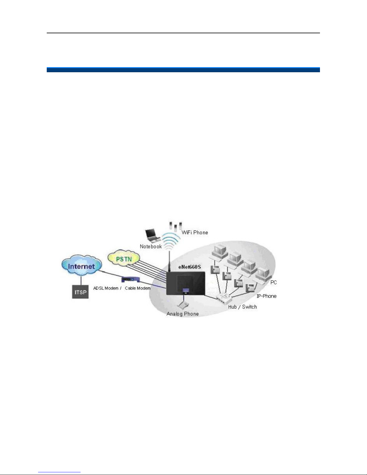
2. Overview of the ENIP2032
The ENIP2032 is an internet telephony desktop phone that connects to the eNet660S
Intelligent Gateway Server with an Ethernet cable. It must be connected through an
Ethernet switch to LAN side or WAN side of eNet660S.
The ENIP2032 can transmit and receive voice via the IP network. Therefore, it can be
deployed and connected at any location in the world between headquarters and remote
branch offices. Since it is a stand-alone and “always-on” terminal, there is no need to have
any active PC to allow it work.
The ENIP2032 equipped with a graphic LCD display, traditional keypad, several function
keys, handset, I/O ports, and PoE (Power-over- Ethernet) and local Power adaptor
connection. It can be installed and placed on the desktop or mounted on the wall.
IP2032 Quick Reference Operating Guide
Page 8 of 34
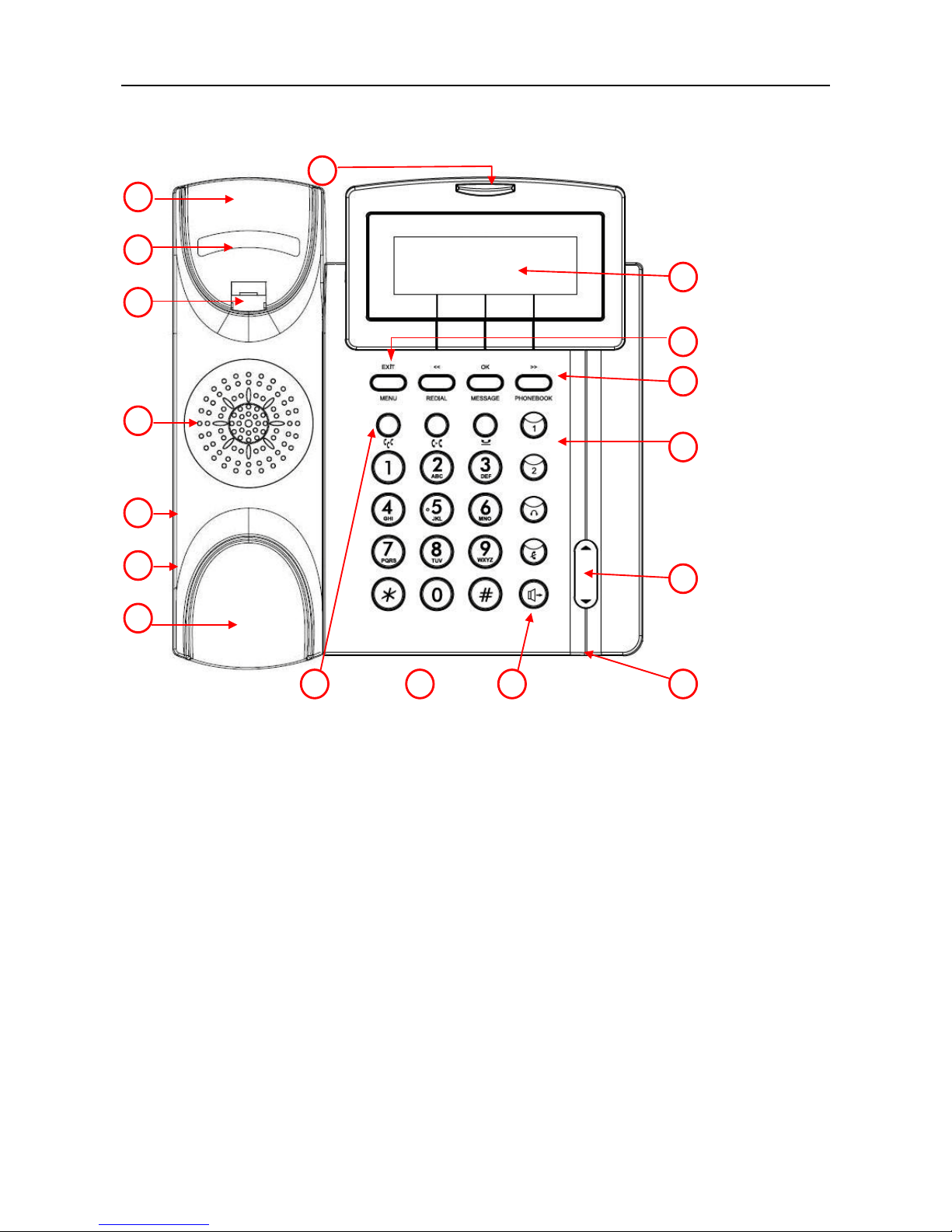
The Front-View of the ENIP2032
The figure below illustrates the front view of the ENIP2032. Each number indicates a
function or feature described in the table.
2
3
4
6
5
1
7
8
15
17
16
10
11
12
13
9
14

IP2032 Quick Reference Operating Guide
Page 9 of 34
No
Part Name
Description of function
1Handset Top Cradle For the placement of handset (Receiver end).
2
Hook Switch To hang-on and hang-off of handset.
3Latch
To latch the handset from drop when phone is
mounted on the wall.
4Speaker For ring and receiver of hands-free talking.
5Handset Cord Jack RJ-9 jack for the handset.
6Headset Cord Jack RJ-9 jack for the headset.
7
Handset Bottom Cradle For the placement of handset (Transmitter end).
8
The message LED. This red LED is used to indicate
incoming call arrival, register status, or message
waiting.
9LCD
The LCD screen is used to display phone’s settings,
time and date, phone numbers, call status and so
forth.
10
The MENU/EXIT key. In idle state, press it to go into
phone’s menu. When in phone’s menu, press it to go
back to previous menu level.
11
The REDIAL/<< key. In idle state, press it and choose
a dialed number to redial. In phone’s menu, press it to
go to upper menu item.
The MESSAGE/OK key. In idle state, press it to dial
mailbox number to acces
s voice messages from
IG6600
. In phone’s menu, it’s used to validate the
selection. For dialing state, it’s used to dial out the
inputted phone number immediately.
The PHONEBOOK/>> key. In idle state, press it to go
into phonebook menu. In phone’s menu, press it to go
to lower menu item.
The above three keys are also softkeys. The key’s
function depends on its
corresponding content displayed on the LCD.
12
Two Line keys. These two keys can be used for line
selection or programmable features. A red
LED is
associated with each key to indicate its line/call/feature
status.
IP2032 Quick Reference Operating Guide
Page 10 of 34
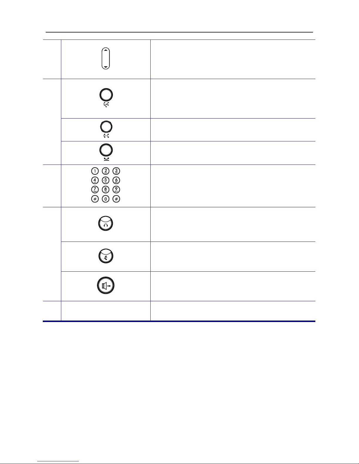
13
The Volume Control/Navigation key. While the phone
is in idle state, the ring volume is adjusted. While in
talking state, the Handset, Speaker, or Headset
receiving volume is adjusted. It is also used to
navigate items in phone’s configuration menu.
14
The CONFERENCE key.
When there are two
connected calls in the meantime, press it to create a
conference call. One party could hear the voice of the
other two parties. It is a voice-bridged function.
The TRANSFER key, press it then dial the other phone
number to transfer a call to another IP phone.
The HOLD key, press it to put the current call on hold.
Press again to resume the held call.
15
[1], [2], …, [9], [*], [0], [
#]: The numeric keypad for
dialing numbers.
16
This HEADSET key. It is used to activate/de-activate
the headset. Press HEADSET
key first then press
SPEAKER key to establish a call by headset.
A red
LED is associated to indicate its status.
This MUTE key. It is used to activate/de-activate the
voice transmission
from this IP phone. A red LED is
associated to indicate its status.
This SPEAKER key is used to switch the voice path
between handset and phone’s speaker. A red LED is
associated to indicate its status.
17 Microphone Hole A small hole for hands-free microphone input under
the front edge of IP phone.
IP2032 Quick Reference Operating Guide
Page 11 of 34
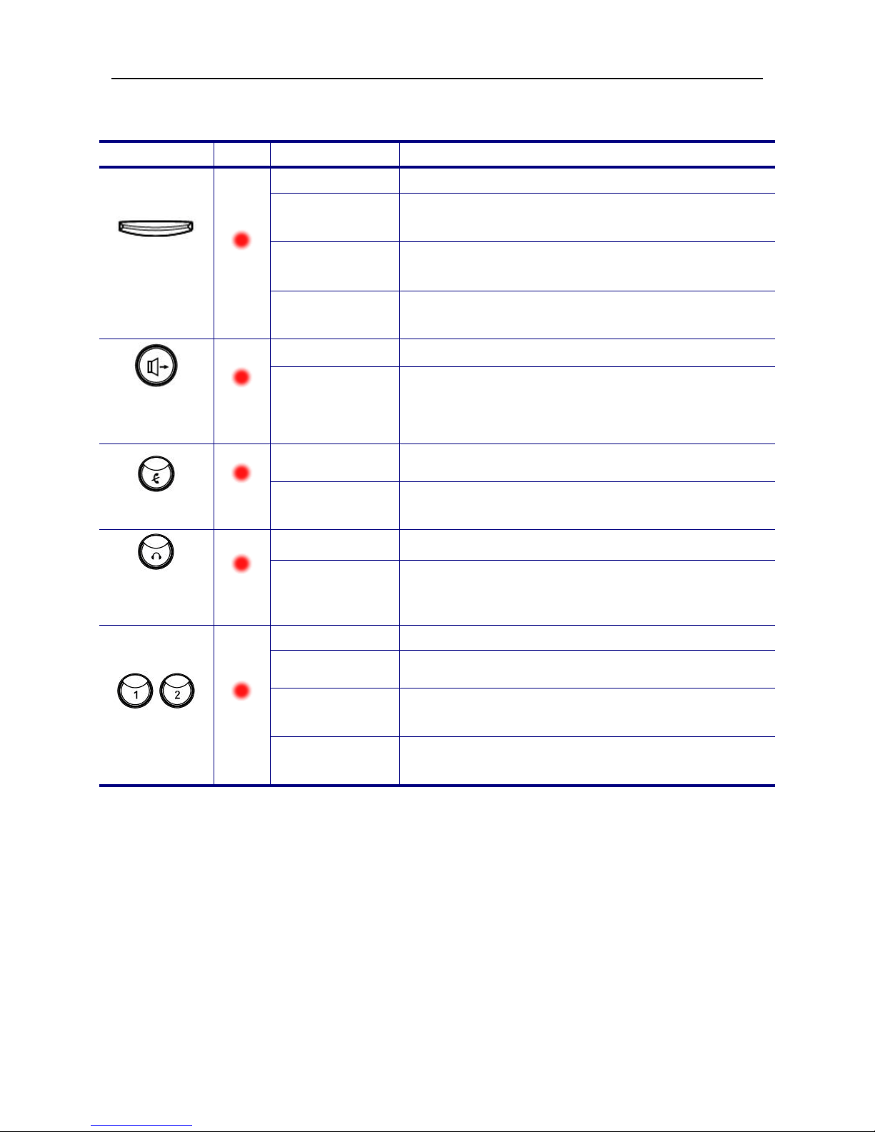
The LED Indication
LED
Color
Status
Description
MESSAGE
LED
Red
Off Idle or no new message.
Blinking
Slowly New voice message indication.
Blinking
Rapidly There is an incoming call.
Blinking
Continuously IP2032 cannot register to IG6600.
SPEAKER
key
Red
Off The hands-free speaker is not in use.
Steady While in on-hook dialing mode or hands-free
talking mode.
MUTE key
Red
Off
The microphone is active for handset, headset or
hands-free mode.
Steady The microphone is inactive for handset, headset or
hands-free mode.
HEADSET
key
Red
Off The headset mode is disabled.
Steady The headset mode is enabled.
Line keys
Red
Off The trunk line is un-activated or idle.
Steady The trunk line is active (dialing, or during a call).
Blinking
Slowly The call of relative trunk line is on hold.
Blinking
Rapidly There is an incoming call from that trunk line.

IP2032 Quick Reference Operating Guide
Page 12 of 34
The LCD Indication
The following figure shows a standard format of the LCD screen. There are 3 soft keys
associated with its operation. For different menu or status, the display format will change.
Date and Time: If the phone is registered to the eNet660S via Plug-n-Play, the eNet660S
will send the info to the phone; if the phone is registered to the eNet660S remotely and
Network Time Server is set, the phone will sync the correct time to time server according to
user’s time zone setting; otherwise, it will show the time passed since the last boot.
Message Indication: If there are voice messages left on the eNet660S, the phone will
show the number of unread messages.
DND Indication:If DND (Do Not Disturb) function is enabled, the phone will show “DND”
on LCD.
Extension Number and Status Indication:There are three line statuses, registered,
un-registered and call forwarded. For registered status, phone will show icon after line
number. For un-registered status, phone will show icon after extension number. When
the phone is registered, if “Call Forward Direct” function is enabled, the icon will
replace the original registered icon.
Date and
Time
Message
Indication
Softkeys
DND Indication
Extension Number
and Status Indication
IP2032 Quick Reference Operating Guide
Page 13 of 34
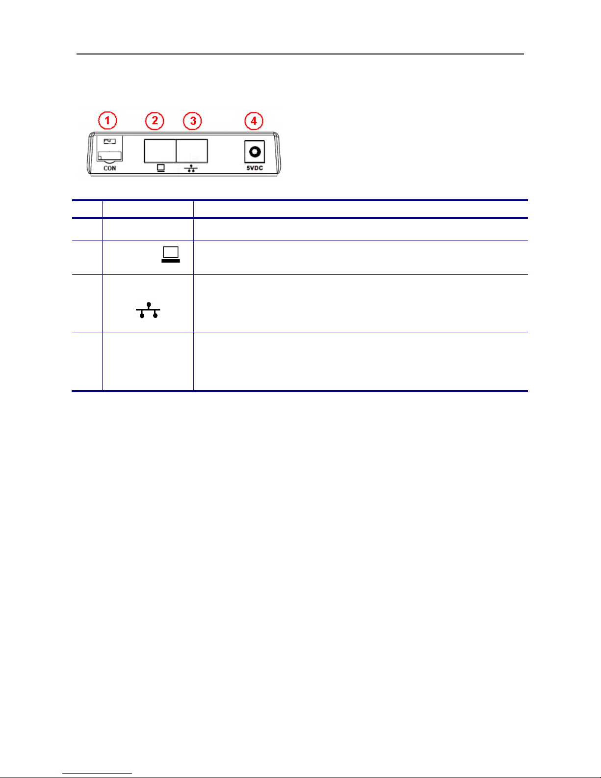
Understanding The Connectors of the ENIP2032
No Part Name Description of function
1 CON Console port reserved for engineering service only.
2 PC port RJ-45 Jack 100/10Mbps Ethernet port for connecting to PC.
Phone could be used as a switch for PC to access the IP network.
3 LAN port
RJ-
45 Jack 100/10Mbps Ethernet port for connecting to IP
network. It also support PoE, the power can come from Ethernet
cable instead using 5V power adaptor for power port.
Note: PoE means Power over Ethernet (IEEE802.3af standard).
4 Power Jack
To connect the power adaptor, please use standard power adaptor
supplied (5VDC/2A). This device can support power auto-switch
function if the AC power is outage and the device will switch the
power from PoE LAN port.
IP2032 Quick Reference Operating Guide
Page 14 of 34
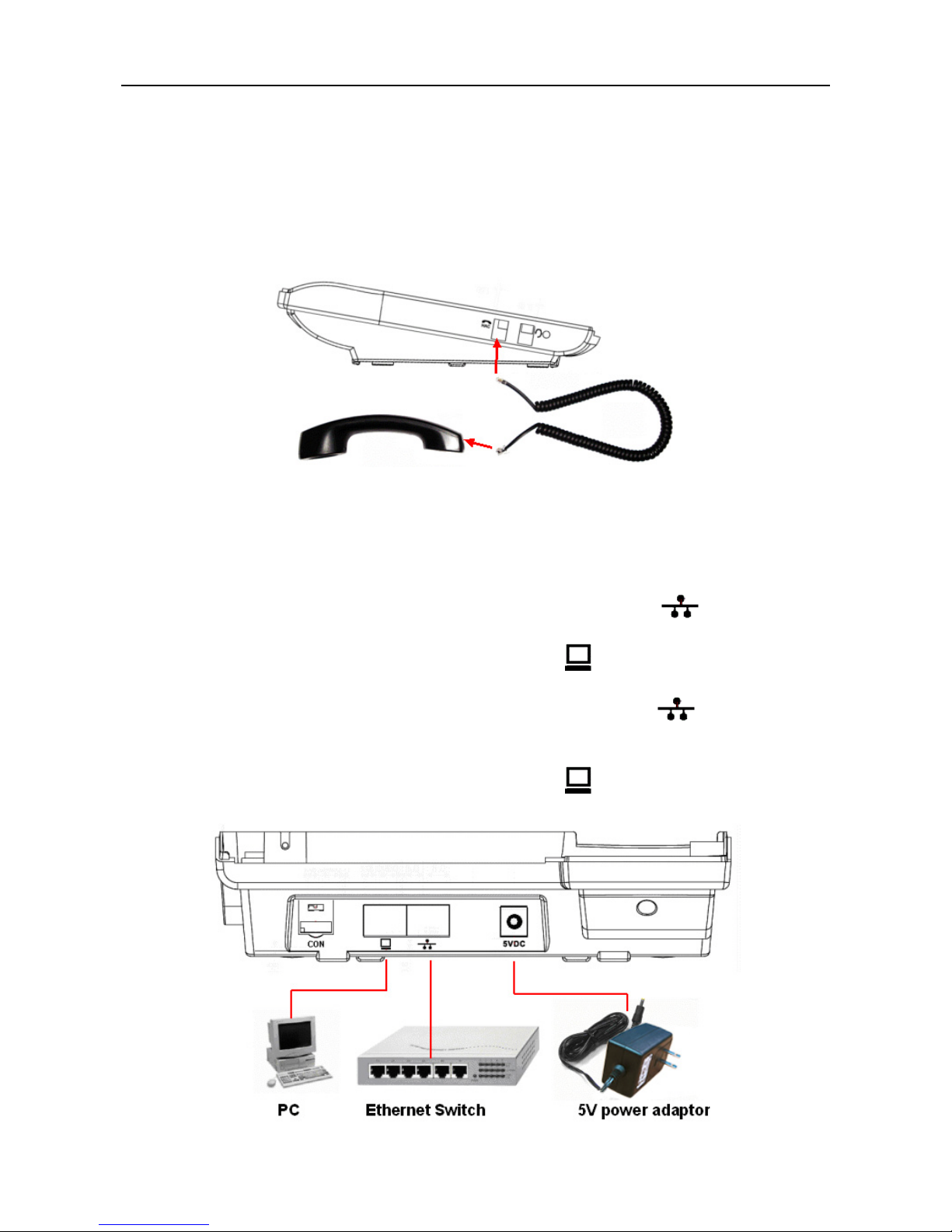
Hardware Installation
Connect the Handset:
Unpacking the box, you can get the handset and handset cord and then you can
connect the handset cord to the handset jack of the phone with the handset as the following
figure.
Connect the Cables:
Then you can find the connection ports on the rear panel of the phone. Please get two
Ethernet cables and follow the installation steps below:
(1) If your Ethernet Switch can offer you PoE (Power over Ethernet) power:
-Please connect an Ethernet cable to the Ethernet Switch from LAN port. Then
you will see the phone is powered and booting.
-Please connect your PC with an Ethernet cable to PC port.
(2) If your Ethernet Switch doesn’t support PoE function:
-Please connect an Ethernet cable to the Ethernet Switch from LAN port.
-Get the 5V/2A power adaptor attached and plug it to the outlet; then plug the barrel to
the “5V DC” Power port. Then you will see the phone is powered and booting.
-Please connect your PC with an Ethernet cable to PC port.

IP2032 Quick Reference Operating Guide
Page 15 of 34
Change the stand’s direction for wall-mount use:
The phone was installed with a wedge stand together in the package. There are two
types for using the wedge stand. One is used to stand on the desk; another is used to place
on the wall. The figure below shows how to take off the wedge stand. There are two clips on
the top edge of the wedge stand. Please press these two clips to out of the top dowels, the
wedge stand can be taken off.
If you want to place the phone on the wall, please follow the steps bellow:
(1) After taking off the wedge stand, please reverse it for 180 degrees (please see the
figure above).
(2) Place the wedge stand back to the phone. Please align the clips to the bottom dowels.
(3) If needed, please drill holes and drive nails into the wall firstly. Please make sure the
hole locations are matched with the holes on the wedge stand.
(4) Mount the phone on the wall.
(5) Finally, plug cables and power adaptor to the phone.

IP2032 Quick Reference Operating Guide
Page 16 of 34
3. General Operations
Introduction
To operate the ENIP2032 with the eNet660S, you need to know some conventions that will
be mentioned in this manual. In the following descriptions, we will introduce some
terminologies for your understanding.
Registering to the eNet660S Server
When the ENIP2032 is connected to LAN side of eNet660S or at WAN side but in the same
subnet, the eNet660S will assign an unused phone number to it. After that, even if the
phone reboots, the eNet660S will assign the same phone number to it. So the ENIP2032
can register to eNet660S automatically each time it is rebooted.
Calls
The “Call” in this manual represents a connection with an outside party. The ENIP2032
supports 2 simultaneous calls, i.e. the ENIP2032 can use 4 channels at the same time. The
ENIP2032 can dial a destination phone number directly. It supports 4 line keys. A User can
press any active line key to choose trunks which are registered to make outgoing calls.
Users can also dial the trunk access number for making an outgoing call. Users can hold
one call and access to the other. Therefore, the ENIP2032 is said to support multiple-call
appearances.
Caller ID & User ID
If callers do not choose to hide their number and if the carrier supports the Caller ID feature,
the caller's phone number is shown on the screen when you receive a call. If the callers
choose to hide their number or the network doesn’t support the Caller ID feature, the
ENIP2032 will display general incoming call information.
To Install the ENIP2032
Before the operating the ENIP2032, you must install the phone on the network. Please refer
to previous section “The Rear-View of the phone”. Connect the LAN port to eNet660S or to
hub/switch with an Ethernet cable, then connect the handset to handset port with a cord.
After that, you could plug the power adaptor to power port, the phone will switch on and
work normally.
To Configure Your ENIP2032 for Service
Furthermore, you must configure the phone before operation can commence. You may
refer to this administrator manual for full information on how to configure all the settings of
IP2032 Quick Reference Operating Guide
Page 17 of 34
the ENIP2032.
Now, if the ENIP2032 is already connected to eNet660S, please see the following chapters
on how to operate the phone.
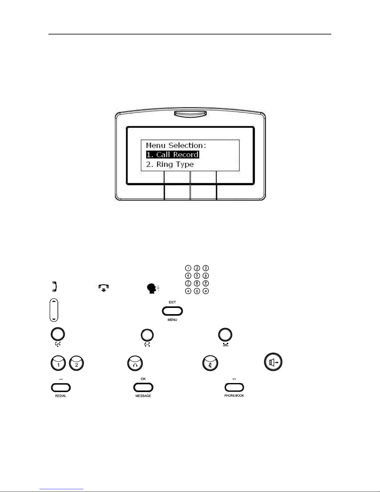
The configuration menu to configure ENIP2032 is as follows:
You may navigate through the menu with the navigation keys. The following sections will
describe how you can setup your ENIP2032 through this menu.
The following lists several meanings of icons for you to easily understand the call features:
Here lists several meanings of icons for you to easily understand the call features:
Off-hook On-hook Talk Keypad
Volume Control/Navigation key MENU/EXIT key
CONFERENCE key TRANSFER key HOLD key
Line keysHEADSET key MUTE key SPEAKER key
REDIAL/<< key MESSAGE/OK key PHONEBOOK/>> key
IP2032 Quick Reference Operating Guide
Page 18 of 34
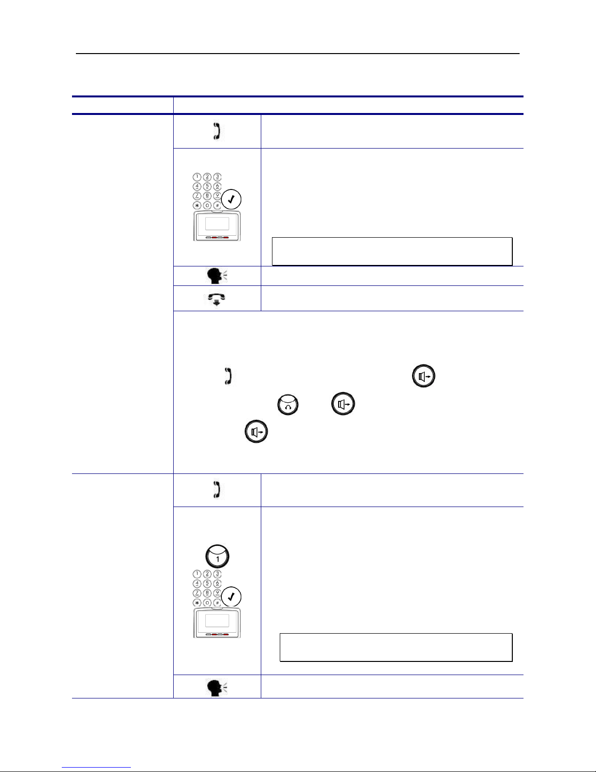
Basic Call Features
Operation
Description
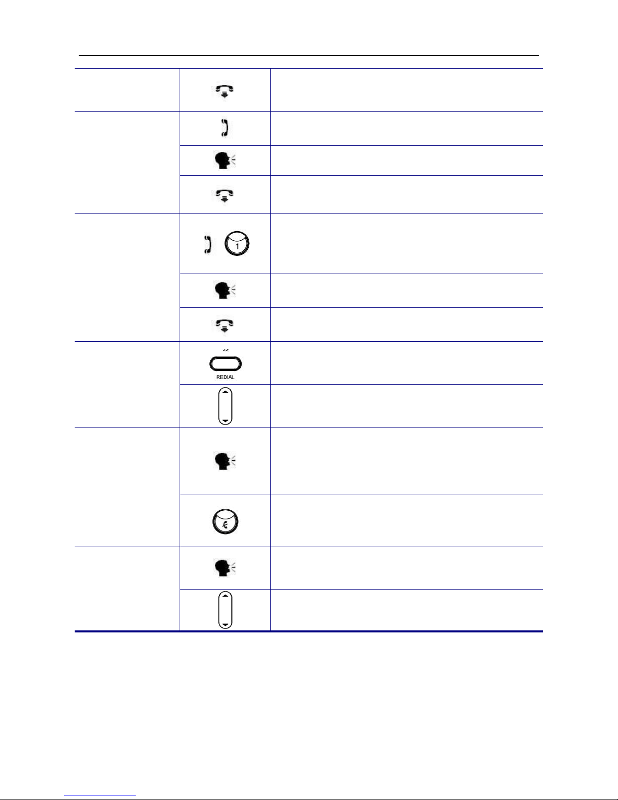
Making a Call
1. Pick-up the handset. You will hear dial tone.
2. Use the keypad to dial a phone number. Press
the ENTER key or “Dial” softkey
to dial out
immediately, or wait for the Dial Timeout setting
to auto-end the dialing. The Phone will then send
out the dialed number to eNet660S. The
eNet660S will route the call to the appropriate
destination.
Note: You can use the “Backsp” softkey to
delete any digits entered.
3. Start talking to called party.
4. Place the handset On-hook when you finished
the conversation.
There are three mode to establish a call for this IP phone, handset
mode, hands-free mode
and headset mode. In this manual, only
handset mode is used for example. In the following features, you can
replace to hands-free mode by pressing key or headset
mode by pressing and key. When the conversation is
over, press key
again to release call. For headset mode,
please prepare a headset first.
Making a Call via
Specific Trunk
1. Pick-up the handset. You will
hear dial tone
played.
2. Press a line key 1 or 2. The LED of line key will
light and the specific trunk line will be engaged.
Use the keypad to dial the target phone number.
Press # key to dial out immediately, or wait for
the Dial Timeout setting to auto-end the dialing.
3. User can also dial the PSTN or IP trunk access
number which the eNet660S registered. For
detail about IP and PSTN trunk, refer to the
eNet660S manual.
Note: You can use the “Backsp” softkey to
delete the last digit.
4. Start talking to the called party.
IP2032 Quick Reference Operating Guide
Page 19 of 34
5. Place the handset On-hook when you finished
the conversation.
Receiving a Call
1. Pick-up the handset during ringing
2. Start talking to caller party.
3. Place the handset On-hook when you finished
the conversation.
Receiving a Call
via Specific
Trunk
1. While getting an incoming call from a specific
trunk, the related line key LED will flash and the
phone may ring. You can pick-up the handset or
press the related line key to receive the call.
2. Start talking to caller party.
3. Place the handset On-hook when you finished
the conversation.
Last Number
Redial
1. Press the REDIAL key, the LCD will show last 30
dialed numbers.
2. Use the volume control key to select a dialed call
and press “Dial” softkey to redial.
Mute the
Microphone
1. While being engaged in a conversation
(handset, headset or hands-free mode), you can
mute the micr
ophone by pressing the MUTE
key.
2. The LED of the MUTE button will light. At this
moment, the user may speak freely, the outside
party will not hear anything.
Adjust the Voice
Volume During a
Conversation
1. During a conversation, if the voice volume is too
low or too high, you may adjust it.
2.
Press the volume control key to adjust the
volume.

IP2032 Quick Reference Operating Guide
Page 20 of 34
Call Record
Operation
Description
Review Dialed
Calls
1. Press the “MENU” softkey.
Call Record
2. Use the volume control key to select the Call
Record item. Press OK key
to validate the
selection.
Dialed Calls
3. Select the Dialed Calls item and validate with
the OK key.
4. Use the volume control key to review the dialed
calls. You may choose to redial the number
(using the “Dial” softkey). Press the “Del”
softkey to delete the selected record. Press the
“DelAll” softkey to delete all records. Press the
“Cancel” softkey to exit the menu.
Review Received
Calls
1. Press the “MENU” softkey.
Call Record
2. Use the volume control key to select the Call
Record item. Press ENTER key to validate the
selection.
Received
Calls
3. Select the Received Calls item a
nd validate
with the OK key.
4.
Use the volume control key to review the
received calls. You may choose to redial the
number (using the “Dial” softkey).
Press the
“Del” softkey to delete the selected record.
Press the “DelAll” softkey to delete all records.
Press the “Cancel” softkey to exit the menu.
Review Missed
Calls
1. Press the “MENU” softkey.
Call Record
2. Use the volume control key to select the Call
Record item. Press OK key
to validate the
selection.
Table of contents


