FHF ResistTel User manual
Explosion-proof telephone
Operating instructions
FHF BA 9701-22 08/11

2
Foreword
Our explosion-proof, weather-resistant telephone is a captivating
product on account of its precision, convenience, long service life and
reliability. It is freely programmable and the optimum choice for adverse
ambient conditions. Be it seawater, high atmospheric humidity, dust or
the toughest mechanical strains, the weather-resistant telephone
accomplishes its aim in any conditions. The reason for this is the robust
eypad made of V4A steel and an extremely solid housing made of
impact-resistant and shoc proof cast-moulding material. All of the
components utilised are even resistant to leeches and lubricants. The
21-component V4A-steel eypad - which can be operated by a user
wearing gloves - and the easily readable alphanumeric display as well
as the uncomplicated menus all ensure simple operation - thus fulfilling
the requirements for a leading-edge and operationally reliable means of
communication. As a telephone suitable for connecting to the public
telephone networ and to private automatic branch exchanges, the
ExResistTel always ensures reliable connections.
ExResistTel ZB is designed for telephone exchange operation and
corresponds to the ExResistTel, except for eypad and display.

3
Table of contents
General operating instructions ................................................................ 4
Overview of the device ............................................................................ 5
Display and keyboard .............................................................................. 8
Contents after unpacking.........................................................................
ZB version notes......................................................................................
Explosion protection – device description ........................................... 10
Explosion protection – device construction .......................................... 11
Explosion protection – characteristic data ........................................... 14
Explosion protection – identification...................................................... 15
Assembly and installation...................................................................... 16
Connection diagram............................................................................... 17
Sling holder ............................................................................................ 18
Drilling diagram ...................................................................................... 18
Start-up................................................................................................... 1
Maintenance........................................................................................... 1
Handset mode........................................................................................ 1
Open Listening....................................................................................... 1
Hands-free talking.................................................................................. 1
Working with the headset ..................................................................... 20
Menu....................................................................................................... 21
Main Menu.............................................................................................. 22
Submenu: Telephone Book................................................................... 23
Submenu: Change Telephone Book..................................................... 24
Submenu: Lock / PIN............................................................................. 25
Submenu: Settings................................................................................. 26
Submenu: Languages............................................................................ 27
Default Settings...................................................................................... 27
Menu overview....................................................................................... 28
Technical data........................................................................................ 2
Guidelines and regulations.................................................................... 32
Service ................................................................................................... 33
Maintenance and servicing.................................................................... 33
Waste disposal....................................................................................... 33
Warning and safety instructions............................................................ 33
CE symbol.............................................................................................. 35
EMC-Directive........................................................................................ 35
Index of catchwords............................................................................... 36
EC Declaration of Conformity................................................................ 37

4
General operating instructions
1. Both the explosion-proof ExResistTel telephone and the ZB version
are designed for connection to dial ports with analogue connection
points.
2. The handset is fitted with a stray-field coil for connecting hearing-
aids. People who use hearing-aids which have an inductive receiver
can receive the earphone signal directly.
3. The optional, external loudspea er has three operating modes –
calling/ringing, open listening and hands-free. If the external
loudspea er is switched on, the internal loudspea er volume will be
reduced.
4. The ZB version is not equipped with eypad and display, therefore
not all the features are available with this version.
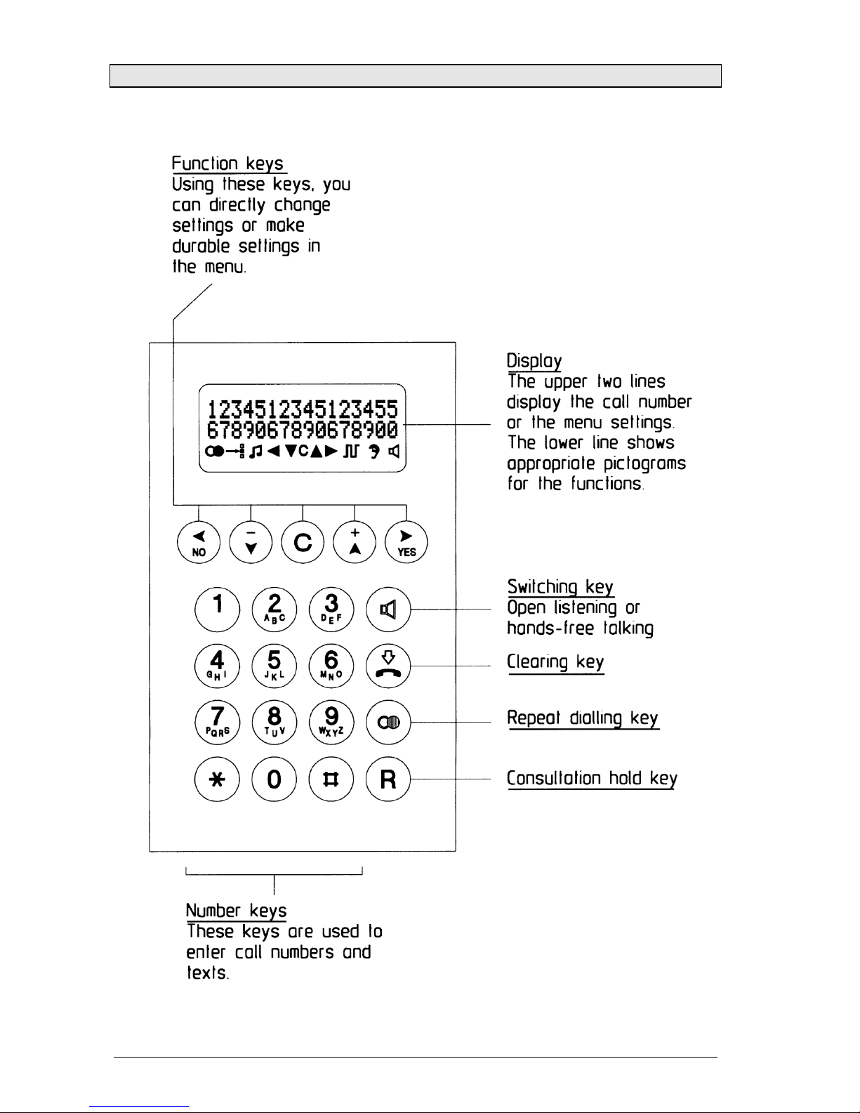
5. The ExResistTel has a handset module with a dry reed contact as a
hoo switch. In order to terminate an existing call connection, the
handset must be hung up. In order to interrupt an existing call
connection, it is sufficient to press the clearing ey on the
eypad.(see page 8)
6. Use the menu to program the appropriate settings. To access the
menu, pic up the handset and press the "YES" ey.
7. If you ta e longer than 2 minutes before you begin ma ing a choice,
the power supply of the exchange may be switched off. If that
occurs, you will no longer hear a dialling tone. In that case, please
replace the handset and wait 2 seconds before pic ing it up again.
8. When a setting is stored successfully, this is confirmed by an
ac nowledgement tone.
9. When you receive a call, the ExResistTel rings at the ringer-volume
level selected by you and, for the duration of the calling sound, the
symbols ( ( ( ) ) ) appears on the display.
10. If you enter a PIN with the menu you can restrict or bloc dial
functions. Forgetting the PIN is the equivalent of losing a ey. If you
forget the PIN, please contact our technical support.
11. You have a guarantee period of 24 months commencing from the
date of purchase. If you have a problem, please contact our
technical support in Germany, located in Mülheim an der Ruhr:
Telephone: 0208 82 68 102 · Fax: 0208 82 68 377
e-mail: [email protected]
From outside of Germany, please prefix the country code:
Telephone: +49 208 82 68 102 · Fax: +49 208 82 68 377
5
If a fault occurs which cannot be rectified by telephone, please send
the whole telephone along with a copy of the sales receipt to the
following address:
FHF
Support ExResistTel
Gewerbeallee 15-19
D-45478 Mülheim an der Ruhr
Germany
If, on examination of the telephone, it is discovered that a fault is not
the case, you will be charged a service fee.
Overview of the device
Note: In case of the ZB version, the eypad and display are replaced by
a solid metal plate.
6
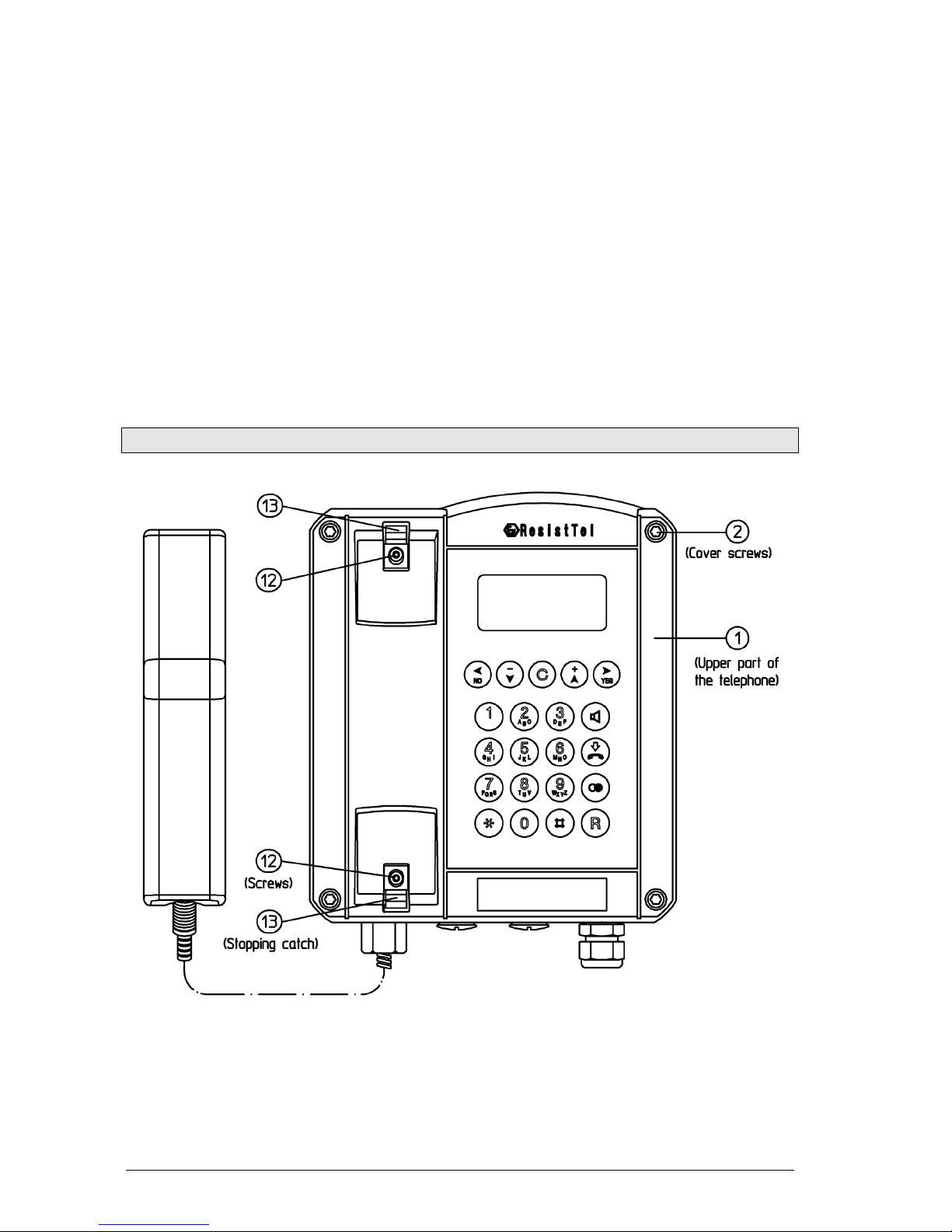
Overview of the device
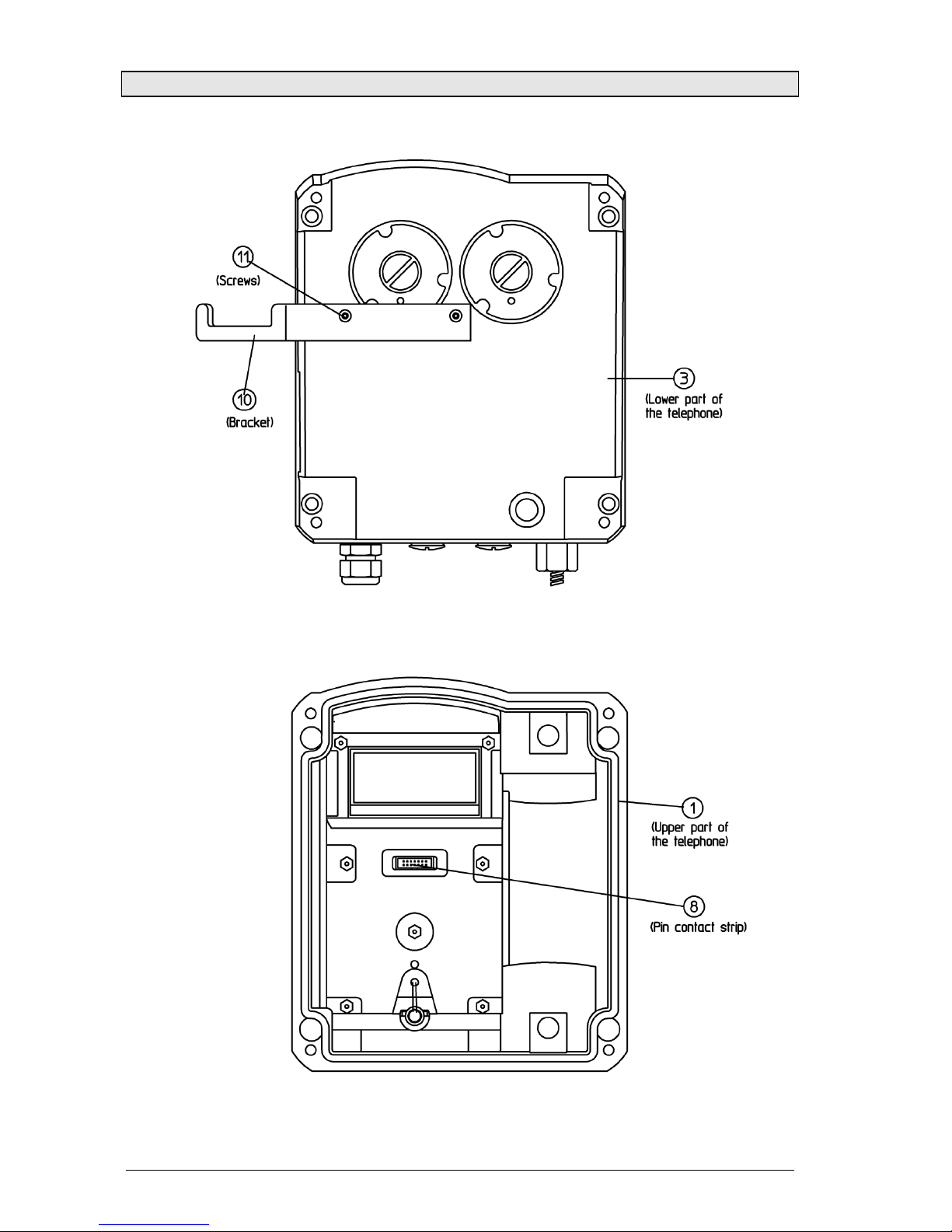
Outside view of telephone lower part
Inside view of telephone upper part
Note: The ZB version is not equipped with a pin contact strip.
7
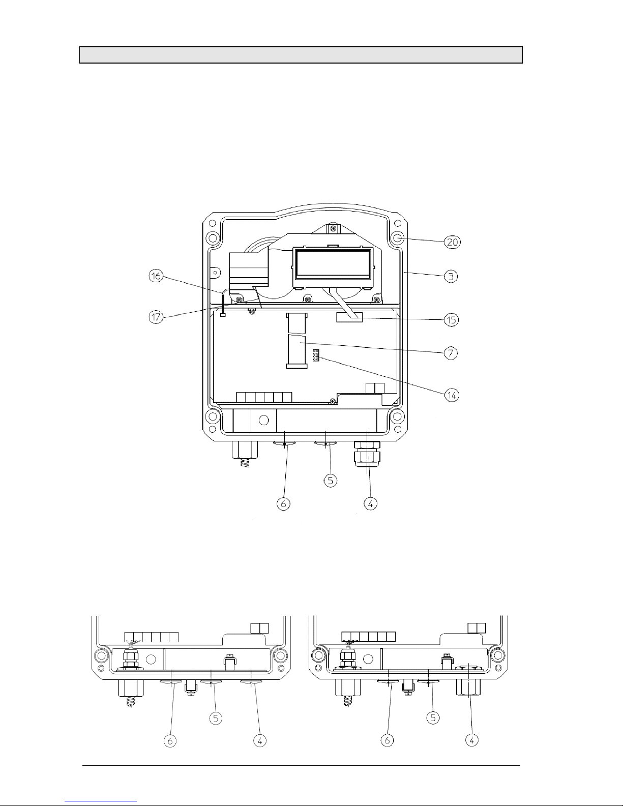
Overview of the device
Inside view of telephone lower part
Protection Class II – Components
Factory supplied with: plastic cable entry.
Note: The ZB model does not have a eypad connector or display.
Protection Class I – Components
Factory supplied with: M20x1.5 threaded hole or a 1/2” NPT metal adapter for
connecting armoured cables or conduit systems.
Cable entry with
screw cap
Sealing plug
Sealing plug
Programming
interface connector
Keypad ribbon cable
with connector
Display interface
connector
Lower part
of telephone
Screws
Loudspea er
cable
Reed
switch cable
Sealing plug Sealing plug
Sealing plug
Sealing plug Metal adapter
Sealing plug
8
Display and eyboard (except for ZB version)

9
Contents after unpac ing
The delivery includes:
- ExResistTel telephone
- Operating instructions
- 2 self-adhesive lettering plates
ZB version notes
The ExResistTel / ZB connects – depending on the features of the
PABX – with the PABX while lifting the handset. The ExResistTel / ZB
can be called also, because the ringing circuit is built in.
Furthermore there are interfaces for operating an optional second
earpiece, an optional secondary ringer and an optional external
loudspea er.
The operating mode „external loudspea er“ is set up by bridging the
terminals 9 and 10 (HSS1, HSS2). With the ZB version this is equivalent
to the open listening mode. The ringer sound is also output via the
external loudspea er.
Note:
The set up of the external loudspea er reduces the volume of the
internal ringer even if the external loudspea er is not connected.
Thus the ZB version offers the following features:
• Establishing a connection by lifting up the receiver
• Ringing by means of integrated ringing device
• Connection of second earpiece
• Connection of secondary ringer
• Connection of external loudspea er

10
Explosion protection – device description
Regarding the explosion protection the ExResistTel telephone and the
ExResistTel telephone in ZB version are identical.
The explosion protection enables the user to ma e and receive calls
within hazardous areas of zone 1, in presence of an explosive gas or
dust atmosphere.
The ExResistTel telephone is manufactured in the following protection
classes:
II 2 G Ex emb [ib] IIC T5 Ex emb [ib] IIC T5
II 2 D Ex tD A21 IP66 T100°C Ex tD A21 IP66 T100°C
-25°C ≤ Ta ≤ +60°C -25°C ≤ Ta ≤ +60°C
Ex emb [ib] IIC T6
II 2 G Ex emb [ib] IIC T6 Ex tD A21 IP66 T80°C
II 2 D Ex tD A21 IP66 T80°C -25°C ≤ Ta ≤ +40°C
-25°C ≤ Ta ≤ +40°C IECEx BVS 11.0033
The ExResistTel telephone is designed for connection with analogue
telephone networ s.
The non-intrinsically safe voltage of the telephone networ is connected
to the terminals 13 and 14 (A, B) in increased safety. In calling/ringing
mode, this voltage is switched to the terminals 15 and 16 (Bell shunt1,
Bell shunt) in increased safety. The terminals 15 and 16 (Bell shunt1,
Bell shunt) are intended for passive consumers, e.g. a passive external,
explosion-proof secondary ringer.
Furthermore, a non-intrinsically safe voltage from the analogue
telephone networ is turned into:
• an intrinsically safe receiver circuit with terminals on the inside of
the telephone housing, for use with the receiver, which is
permanently connected to the telephone housing, and
• intrinsically safe circuits with terminals within the telephone housing
for connecting an intrinsically safe headset or, optionally, an
intrinsically safe second earpiece, and
• an intrinsically safe circuit with terminals within the telephone
housing for the connection of an intrinsically safe loudspea er.
The accessories headset, second earpiece, external loudspea er and
external secondary ringer are not parts of the ExResistTel telephone,
but optional extras.

11
Explosion protection – device construction
The unvarnished housing of the ExResistTel telephone consists of an
electrostatically conductive cast-moulding equipped with a stainless
steel eypad. The eypad front plate contains a display sealed by a
viewing window.
The ZB version comprises no eypad and no display area, but a solid
front plate.
The housing consists of a rectangular lower part, in which there has
been placed a tray for mounting the electronic parts, as well as a
vaulted cover with a eypad.
The cover and the lower part of the housing, divided by a surrounding
seal only, are pressed together by four screws. The cover ma es up
both the non-intrinsically safe and the intrinsically safe electrical
enclosure. The electronics circuit board is situated in the tray of the
lower part of the housing, completely embedded in a protective
compound.
Non-intrinsically safe terminals in increased safety:
Protruding from the compound (see connecting diagram on page 17), a
4-pole increased-safety terminal row is intended for connecting the non-
intrinsically safe telephone networ (A, B), terminals 13 and 14, as well
for connecting an optional, external, explosion-protected secondary
ringer (Bell shunt1, Bell shunt), terminals 15 and 16.
12
Intrinsically safe terminals:
Protruding from the compound (see connecting diagram on page 17), a
12-pole intrinsically safe terminal row is intended for connecting the
receiver, which is permanently connected with the telephone housing,
terminals 1 to 4, as well as the intrinsically safe accessories, terminals 5
to 12.
The terminals 7 and 8 are intended for the connection of dynamic
receiver insets, li e the ones used in second earpieces and headsets.
This output thus can be used for connecting a second earpiece or a
headset, which means that a second earpiece and a headset cannot be
connected simultaneously.
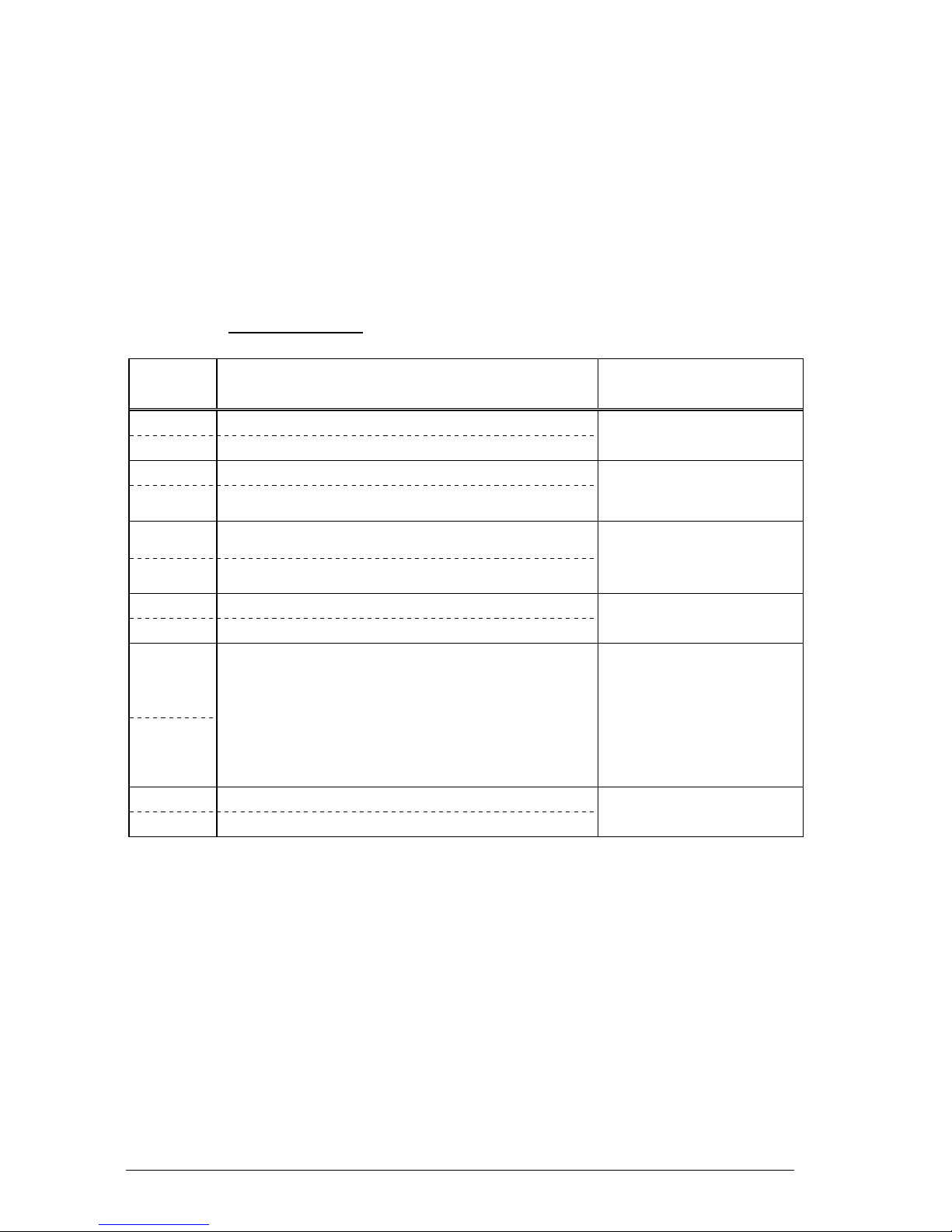
Terminal Note Use
1 Dynamic receiver inset connection 1
2 Dynamic receiver inset connection 2 Receiver inset
3 Electret-foil microphone connection (+)
4 Electret-foil microphone connection (-) Receiver
microphone
5 Electret-foil microphone connection (+)
6 Electret-foil microphone connection (-)
Headset
Microphone, not for
ZB version
7 Dynamic receiver inset connection 1
8 Dynamic receiver inset connection 2
Headset or
second earpiece
9
10
Jumper between the terminals 9 and 10
is identified by the telephone as
headset connected.
or
– in case of the ZB version – as
external loudspea er connected.
Headset
identification or
–ZB version
–identification of
external
loudspea er
11 Dynamic loudspea er connection 1
12 Dynamic loudspea er connection 2
External
loudspea er
To connect accessories, you must replace the blind plugs screwed into
the telephone housing by explosion-proof cable glands (M20x1.5).
Before connecting intrinsically safe accessories, and if a system
certificate for the intended connection does not exist, the constructor
should perform an evaluation of the intrinsic safety according to the PTB
report “Zusammenschaltung nichtlinearer und linearer eigensicherer
Strom reise“ (Interconnection of non-linear and linear intrinsically safe
electrical circuits), PTB-ThEx-10, from November 1999 (ISBN 3-89701-
440-9).
The technical data for the evaluation of the intrinsic safety can be found
in the chapter “Explosion protection – characteristic data”.

13
Further information see EN60079-14 “Electrical apparatus for explosive
gas atmospheres - Part14: Electrical installations in hazardous areas”
and EN50281-1-1 “Electrical apparatus for use in the presence of
combustible dust”. The user shall observe the standard EN50281-1-2
(IEC61241-1-2) if the device operates in hazardous areas with
combustible dust.
A metal brac et is supplied for hanging up the intrinsically safe second
earpiece or headset. The metal brac et should be attached to the
telephone by means of the two threaded bushes in the floor of the
telephone housing. The corresponding bores in the metal brac et can
be used to screw the brac et securely onto to the housing floor (see
overview of the device on page 6). Thus, if the constructor wants to use
the metal brac et, the first thing he has to do, is to fix it to the housing
floor. Subsequently, the device may be mounted on the wall.
Intrinsically safe programming interface
An 8-pole, intrinsically safe contact strip (14) (see overview of the device
on page 7) protrudes from the compound. This contact strip is
exclusively used by the manufacturer for programming purposes. Do not
switch any circuits by using the contact strip. The constructor may not
perform any ind of programming.
Intrinsically safe display interface
An 8-pole, intrinsically safe contact strip with a soldered-on circuit board
(15) (see overview of the device on page 7) protrudes from the
compound. The circuit board is equipped with a zero power plug for
connecting the intrinsically safe LC display film conductor. Connect the
built-in display only to this interface.
Intrinsically safe strand connection to the built-in loudspea er
An intrinsically safe 2-pole strand conductor (16) (see overview of the
device on page ) goes from the compound to the built-in loudspea er.
The strand is soldered onto the circuit board below the compound, as
well as onto the loudspea er.
Intrinsically safe strand connection to the reed switch
An intrinsically safe, 2-pole strand conductor (17) goes from the
compound to a circuit board with a reed switch (see overview of the
device on page 7). On the compound-covered circuit board the strand
runs underneath the compound, and on the other circuit board it is
soldered onto the reed switch.

14
Intrinsically safe eypad connection
An intrinsically safe, 14-pole ribbon cable with plug bush (18) comes out
of the compound. Prior to screwing the device parts together, connect
this plug bush with the 14-pole pin contact strip in the housing cover.
Explosion protection – characteristic data
1. Non-intrinsically safe electrical circuits
1.1 Telephone networ
(Terminals A / B No.: 13 – 14)
Maximum input voltage Um (ringing voltage) AC 90 V
Admissible frequency range 16...54 Hz
or
Maximum input voltage Um (supply voltage) DC 66 V
Maximum rated input current 100 mA
Maximum input short circuit current IK 35 A
(At the input of this device there is a melting fuse
with a brea ing capacity of 35 A)
1.2 External secondary ringer:
For connection with passive consumers only
(Terminals Bell shunt1 / Bell shunt No.: 15 –16)
Maximum ringing voltage AC 90 V
Frequency range 16...54 Hz
or
Maximum supply voltage DC 66 V
2. Intrinsically safe electrical circuits
2.1 Headphones accessory (microphone)
(Terminal pair HSM No.: 5 – 6)
Maximum output voltage Uo17 V
Maximum output current Io90 mA
Maximum output power Po80 mW
Maximum external capacitance Co375 nF
Maximum external inductivity Lo1mH
2.2 Headphones accessory (receiver inset) or second earpiece
(Terminal pair HSR No.: 7 – 8)
Maximum output voltage Uo17 V
Maximum output current Io110 mA
Maximum output power Po190 mW
Maximum external capacitance Co375 nF
Maximum external inductivity Lo1.2 mH
15
2.3 Headphones accessory (identification)
(Terminal pair HSS No.: 9 – 10)
Maximum output voltage Uo17 V
Maximum output current Io8mA
Maximum output power Po33 mW
Maximum external capacitance Co375 nF
Maximum external inductivity Lo100 mH
2.4 External loudspea er
(Terminal pair SPK No.: 11 – 12)
Maximum output voltage Uo6,6 V
Maximum output current Io250 mA
Maximum output power Po370 mW
Maximum external capacitance Co22 µF
Maximum external inductivity Lo0.3 mH
2.5 All intrinsically safe output electrical circuits have a linear
output characteristic curve.
3. Ambient temperature range
-25°C < Ta < 60°C for temperature class T5
-25°C < Ta < 40°C for temperature class T6
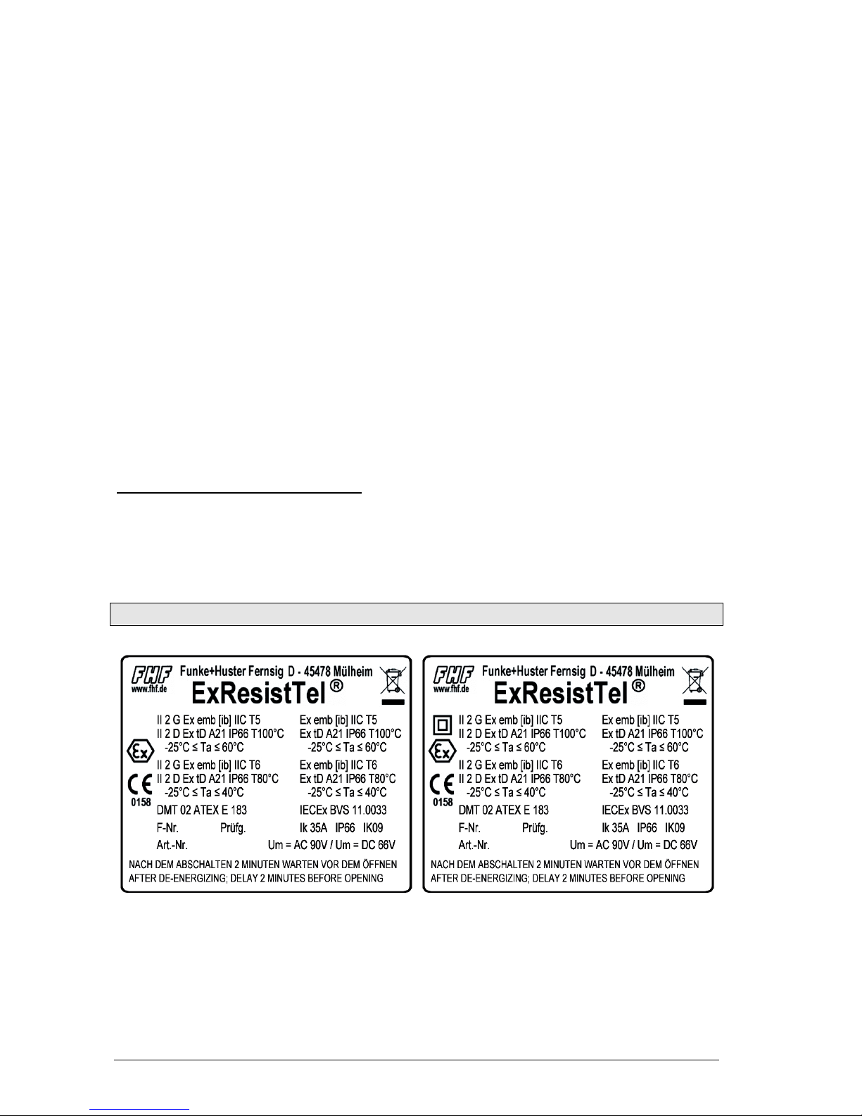
Explosion protection – identification
Figure Type Plates
Telephone / Telephone ZB, Type ExResistTel
Insulation class I Insulation class II

16
Assembly and installation
The device must be installed on a plane surface only, in vertical
operating position. Loosen the cover screws (2) (see overview of the
device on page 5 to 7). and detach the upper part of the telephone (1).
If the optional accessory headset or a second earpiece is being
employed, attach the brac et (10) using two screws (11) to the rear
panel of the lower part of the telephone. (With the accessories named
before, the brac et and screws are in the scope of delivery. With all
accessories a cable gland is delivered.) Put four screws, having a head
diameter of 10 to 13 mm into the holes (20) and attach the lower part of
the telephone (3) to the wall or to a holder.
Installation differs depending on the type of telephone model. On the
telephone with factory equipped plastic cable entry, the telephone networ
cable should be passed through the cable entry (4) and connected to
terminals 13 and 14 (A, B) in accordance with the connection diagram. Only
use cables with a sheath diameter of 5 to 9 mm because otherwise the IP66
enclosure protection rating may be compromised.
On the telephone with the M20x1.5 threaded opening or the 1/2” NPT
threaded opening, the customer is responsible for mounting a cable entry.
Follow the manufacturer’s instructions supplied with the cable entry
assembly. Only cable entries with EU type approval for IP66 enclosure
protection rating and -25°C ≤ Ta ≤ 60°C should be used and they should
provide a good seal and fit tightly to the cable. On this model (Protection
Class I), ma e sure the PE (protective earth) wiring is connected properly.
Corresponding connection points are provided and mar ed inside and
outside of the housing. The telephone networ cable must be connected to
terminals 13 and 14 (A, B) as shown on the connection diagram. If a torque
of more than 20 Nm is used to tighten down the sealing rings of the cable
entry, then the side of the cable entry assembly nearest the housing should
be secured against rotating.
Connecting a second ringer (bell-shunt) (optional accessory)
Remove the sealing plug (5) and tighten the M20x1.5 cable gland
cap. Insert the wire of the second ringer and place it on the terminals
in accordance with the connection diagram. Only utilise wires which
have a sheath diameter of 5 to 9 mm because otherwise the IP66
housing protection standard is not guaranteed.
Connecting an external loudspea er (optional accessory)
Remove the sealing plug (6) and tighten the M20x1.5 cable gland
cap. Insert the wire of the loudspea er and place it on the terminals
11 and 12 (SPK+,SPK-) in accordance with the connection diagram.
Only utilise wires which have a sheath diameter of 5 to 9 mm
because otherwise the IP66 housing protection standard is not
guaranteed.

17
Connecting a headset (optional accessory)
Remove the sealing plug (6) and tighten the M20x1.5 cable gland
cap. Guide the specially-manufactured wire with the headset soc et
(included in the delivery of the headset) through the cable screw cap
and place it on the terminals 5 through 10 (HSM+, HSM-, HSR+,
HSR-, HSS1, HSS2) in accordance with the connection diagram.
Only the wire included in the delivery for the headset should be used
because otherwise the IP66 housing protection standard is not
guaranteed.
Connecting a second earpiece (optional accessory)
Remove the sealing plug (6) and tighten the M20x1.5 cable gland
cap. Insert the wire of the second earpiece and place it on the
terminals 7 and 8 (HSR+, HSR-) in accordance with the connection
diagram.
Prior to assembly, chec cover seal for tightness.
Using the plug connector (7), plug the ribbon cable onto the pin contact
strip (8) in the upper part of the housing.
Attach the upper part of the telephone and fasten it to the lower part of
the telephone with the four cover screws (2).
Upon disassembly of optional accessories, suited blind plugs must be
used to close the resulting openings.
Connection diagram

18
Sling holder
The holding strength for the handset is continuously adjustable.
Loosen the screws (12) and move the stopping catches (13). Pushing
the stopping catches together increases the holding strength whereas
pulling them apart reduces it. Tighten the screws again.
Drilling diagram
or making a drilling template please use the following dimensions (in
mm).
The diameter of the drilled hole is dependent on the screw employed
(screw diameter max. 8 mm) and the type of supporting base material
(steel, wood, concrete, plasterboard etc.) and must be chosen
accordingly.

19
Start-up
The ExResistTel telephone is ready for operation as soon as it has been
connected to the telephone networ .
Maintenance
The ExResistTel telephone contains no parts that have to be
maintained.
Handset mode (except ZB version)
When you pic up the handset, you are in handset mode. Using the
eys and , you can adjust the handset volume for tal ing. If you
wish to durably change the handset volume, use the menu "Settings /
Handset volume". Using the ey you can switch into open listening
mode. If you eep the ey depressed and replace the handset, you
switch to hands-free tal ing mode.
Open Listening mode (except ZB version)
Using the eys and , you can adjust the loudspea er volume for
tal ing. If you wish to change the loudspea er volume durably, use the
menu "Settings / Loudspea er". The handset volume cannot be
changed in open listening mode. Using the ey , you can switch to
handset mode. If you eep the ey depressed and replace the
handset, you switch to hands-free-tal ing mode.
Hands-free mode (except ZB version)
If you switch on the ExResistTel using the ey you are in hands-
free-tal ing mode. Using the eys and you can adjust the
loudspea er volume for tal ing. If you wish to durably change the
loudspea er volume, use the menu "Settings / Loudspea er". You end
the call using the ey . If you pic up the handset, you switch to
handset mode.

20
Wor ing with the headset (except ZB version)
If the headset has been connected correctly, it ta es the place of hands-
free tal ing. For this reason, hands-free tal ing with the headset is not
possible. If you switch on the ResistTel with the ey , you are
operating in headset mode. If you lift the handset while in headset
mode, the handset assumes a higher priority. That means that it is
possible to spea and listen using the handset but, in this mode, it is
only possible to listen with the headset.
Comparison of the operating states without and with connected
headset:
Operation without the headset Operation with the headset
Handset mode Handset mode with the headset
- Handset can spea and listen
- Headset can only listen
- Loudspea er is off
Open Listening mode Open Listening with the headset
- Handset can spea and listen
- Headset can only listen
- Loudspea er is on
Hands-free mode Headset mode
- Handset is replaced
- Headset can spea and listen
- Loudspea er is off
Using the eys and you can adjust the headset volume for
tal ing. If you wish to durably change the headset volume, use the menu
"Settings / Headset Volume". You end the call using the ey .
Table of contents
Other FHF Telephone manuals


