Tritec TRI-Xi Outdoor 1.8 User manual
MULTILINGUAL
TRI-Xi Outdoor
User Manual
Benutzerhandbuch
Manuel de l’Utilisateur
Manual del Usario
Manuale dell’Utente
TRI-Xi 1.8 • TRI-Xi 3.6 • TRI-Xi 5.4

Choice of Language - Sprachauswahl - Choix de la langue -
Selección de idioma - Scelta della lingua
Page 2 English UK
Seite 13 Deutsch
Page 25 Francois
Página 36 Español
Pagina 48 Italiano
L00410353-02 1

Contents
1. Introduction 3
2. Function Description 4
Definition of Operation Modes 4
PV Configuration 4
LEDs 5
Display 6
Overview Menu Section A 6
Overview Menu Section B 7
3. Troubleshooting 10
Troubleshooting 10
Inverter Event Messages 10
4. Maintenance 12
Maintenance 12
Cleaning the Cabinet 12
Cleaning the Heatsink 12
Contents
2L00410353-02
1. Introduction
1.1. Introduction
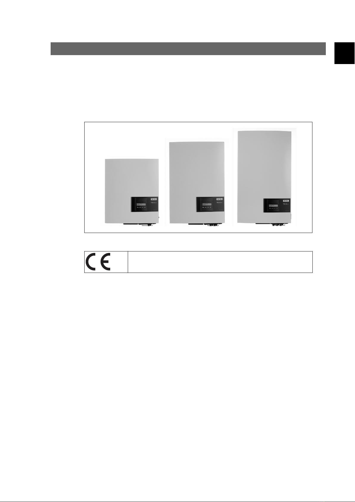
This manual describes TRITEC photovoltaic inverters. These products are among the most tech-
nologically advanced and efficient inverters on the market and are designed to supply the owner
with reliable solar energy for many years.
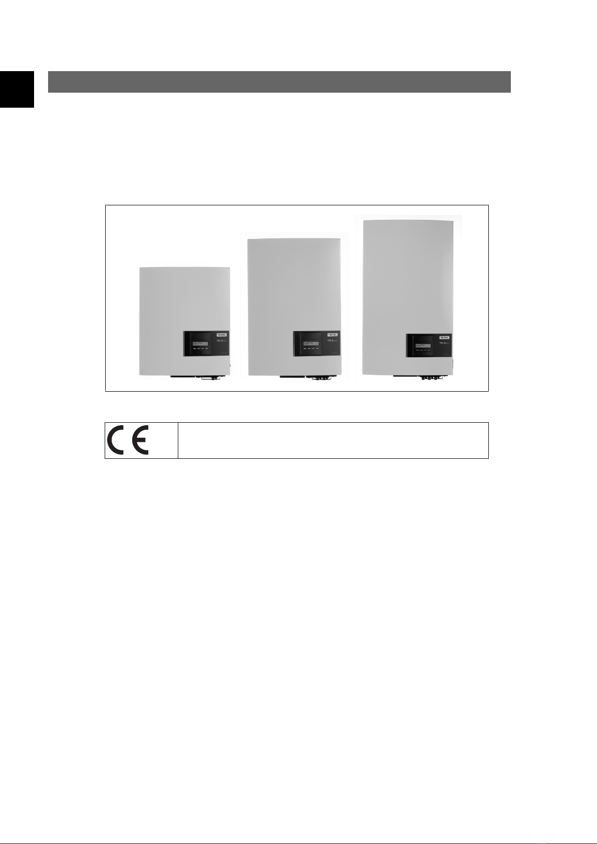
Illustration 1.1: TRI-Xi Range - Outdoor with Display
CE marking - This certifies the conformity of the equipment with the regula-
tions which apply in accordance with the directives 89/336/EWG and 72/23/
EWG.
1. Introduction
L00410353-02 3
1

2. Function Description
2.1. Definition of Operation Modes
The inverter has four modes:
Standby mode:
In standby mode, the inverter is ready to switch into connecting mode. As decision variable the
input voltage of the PV generator is used. If the input voltage exceeds a preset nominal value,
the inverter shifts from “standby” to “connecting”, or continues into the operation mode “OFF” if
the PV voltage drops.
Connecting mode:
After performing the system tests, which check whether all connection conditions are met, the
inverter goes from standby mode to connecting mode. During the specified cut-in time, the in-
verter continues testing the system values and connects the inverter to the grid if the system tests
are okay. The minimum cut-in time is specified by the supplier and authorities and can vary from
region to region.
Grid mode:
In this mode, the inverter is connected to the grid and supplies power to the grid. The inverter is
only uncoupled from the grid in case of abnormal grid conditions or when PV power is not available.
Off:
If there is no PV power available to supply the inverter, the inverter waits ten minutes (specified
value) before it disengages. In this mode, the power supply to all processors is switched off to
conserve energy. This is the normal night mode.
2.1.1. Grid Surveillance
In order to safeguard the people working on AC power lines and the inverter, the inverter shuts
down in the event of abnormal grid conditions or failures. The inverter continuously monitors grid
voltage and frequency by means of an internal control circuit. Subsequently, the inverter will re-
connect as soon as the grid is within limits.
2.1.2. PV Configuration
Upon connecting to grid an automatic test of the PV module wiring is performed by the inverter.
This test is made in order to determine the wiring configuration of the modules. It is established
whether the modules are connected in individual string configuration or in parallel string config-
uration and the inverter is automatically configured accordingly.
The test works by activating the inputs one by one. The test takes 1-2 minutes and the inverter
continues to produce energy meanwhile.
For TRI-Xi 5.4, 2 out of 3 DC modules must be powered for the test to run. If not enough PV
power is available to power 2 modules, the test is postponed until sufficient PV power is available
for the second DC module to run.
2. Function Description
4L00410353-02
2
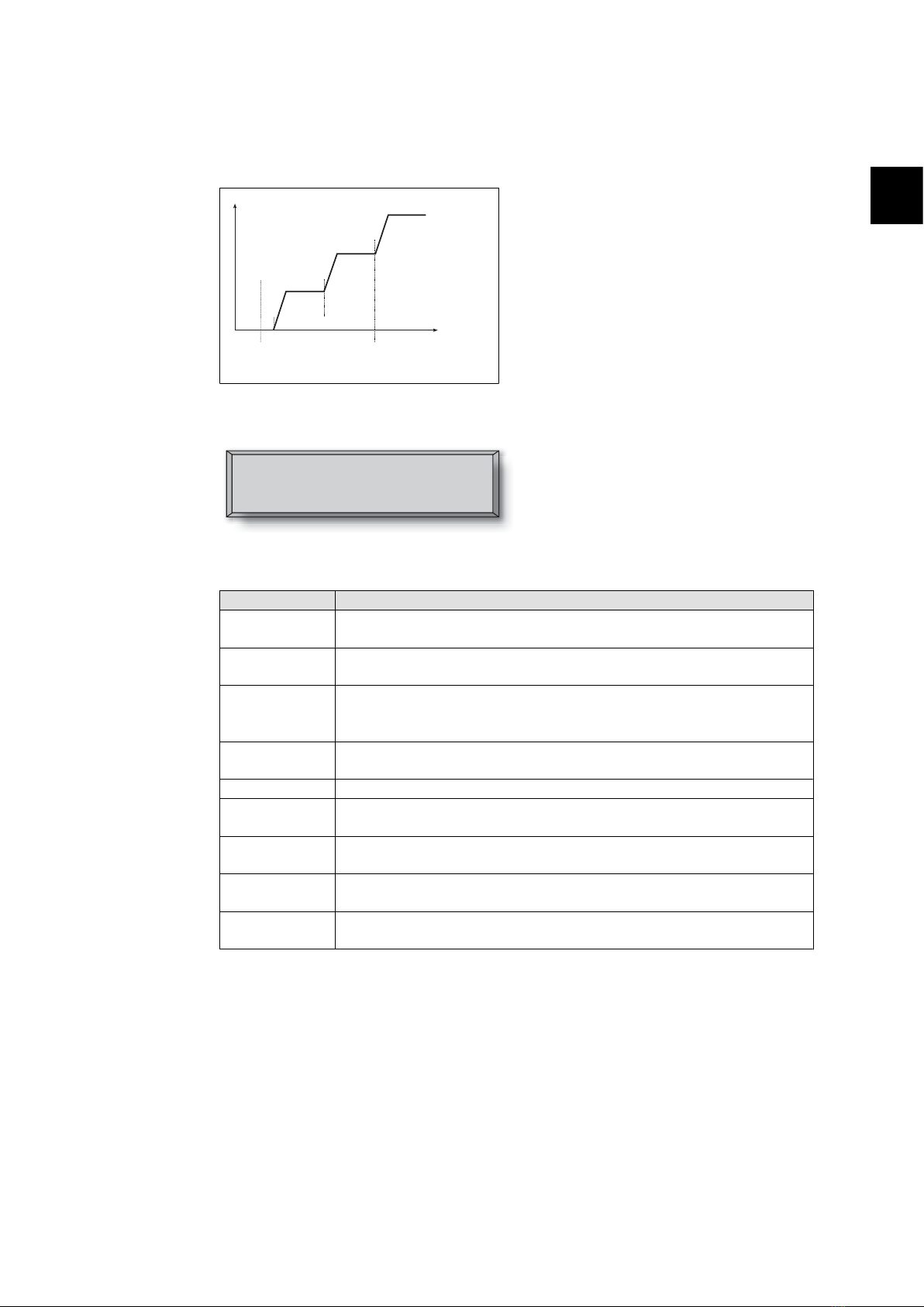
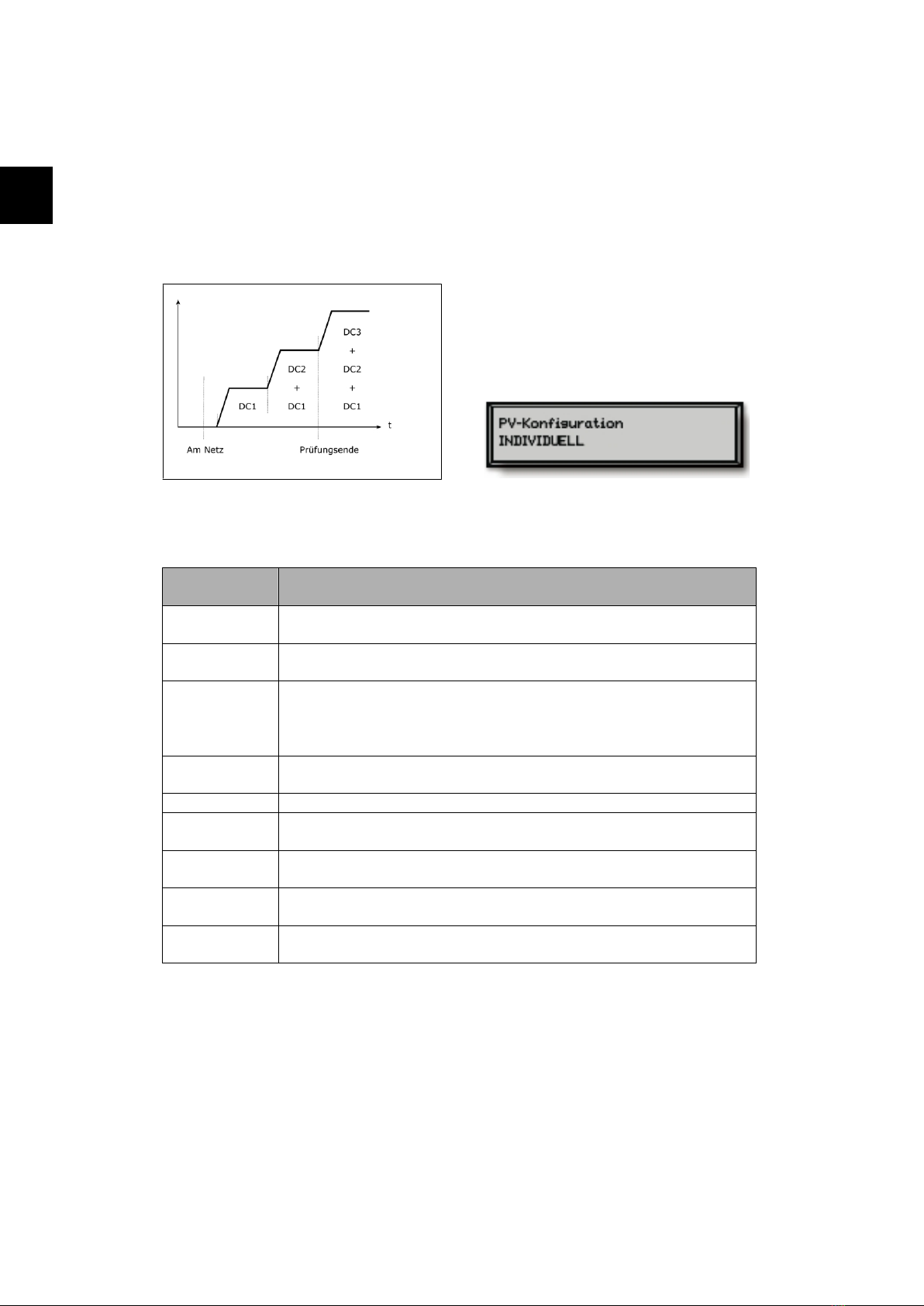
For inverters with display, the result of the test can be read in menu B in the display menu called
PV configuration. Upon test completion the display will automatically show the PV configuration
detected; however, only if the buttons on the display have not been used in the past 3 minutes.
DC3
+
DC2 DC2
+ +
DC1 DC1 DC1
t
On Grid Test end
Illustration 2.1: PV configuration test
The display readout shows the status of the
test. The first line shows that this concerns the
PV configuration and the second line shows
which status the test is in or which configura-
tion it has detected.
PV configuration
INDIVIDUAL
The status field may show the following:
Display Text Description
IDLE PV configuration test has not yet been run. Shown before the inverter con-
nects to grid.
OFF PV configuration test is disabled. Applicable to TRI-Xi 1.8 and to inverters
where the test is otherwise disabled.
WAITING The PV configuration test is ready to run, but only solar radiation for one PV
input is available. (Applicable to TRI-Xi 5.4 , the inverter can only determine
the configuration of all three modules, when two are running)
PV-AUTODE-
TECTING
The PV configuration test is running. No result yet.
INDIVIDUAL The PV modules are connected in individual string configuration
PARALLEL 1-2* The PV configuration has ended, concluding that inputs 1 and 2 are connected
in parallel string configuration.
PARALLEL 1-3* The PV configuration has ended, concluding that inputs 1 and 3 are connected
in parallel string configuration.
PARALLEL 2-3* The PV configuration has ended, concluding that inputs 2 and 3 are connected
in parallel string configuration.
PARALLEL 1-2-3 The PV configuration has ended, concluding that inputs 1, 2 and 3 are con-
nected in parallel string configuration.
Table 2.1: PV Configuration Test Status Field Text
*) The “PARALLEL 1-2” is only allowed for the TRI-Xi 3.6 inverter. The “PARALLEL 1-2”, “PARALLEL
1-3”, and “PARALLEL 2-3” is not allowed for the TRI-Xi 5.4 inverter.
2.1.3. LEDs
The green LED indicators show the production in percentage of the nominal inverter power rating.
The leftmost green LED is always lit when the inverter is connected to the grid. While connecting
to grid both the red LED and the leftmost green LED will be on. When the inverter is off grid, the
red LED to the left is lit to indicate that the inverter is in standby mode. No green LEDs are lit. If
2. Function Description
L00410353-02 5
2
no LED’s are on the inverter is off. If the inverter is forced into standby mode because of an event
in the inverter or the peripheral connections, e.g. disconnection from the grid, the red LED starts
flashing.
For a description of events, please refer to the section on
Troubleshooting
.
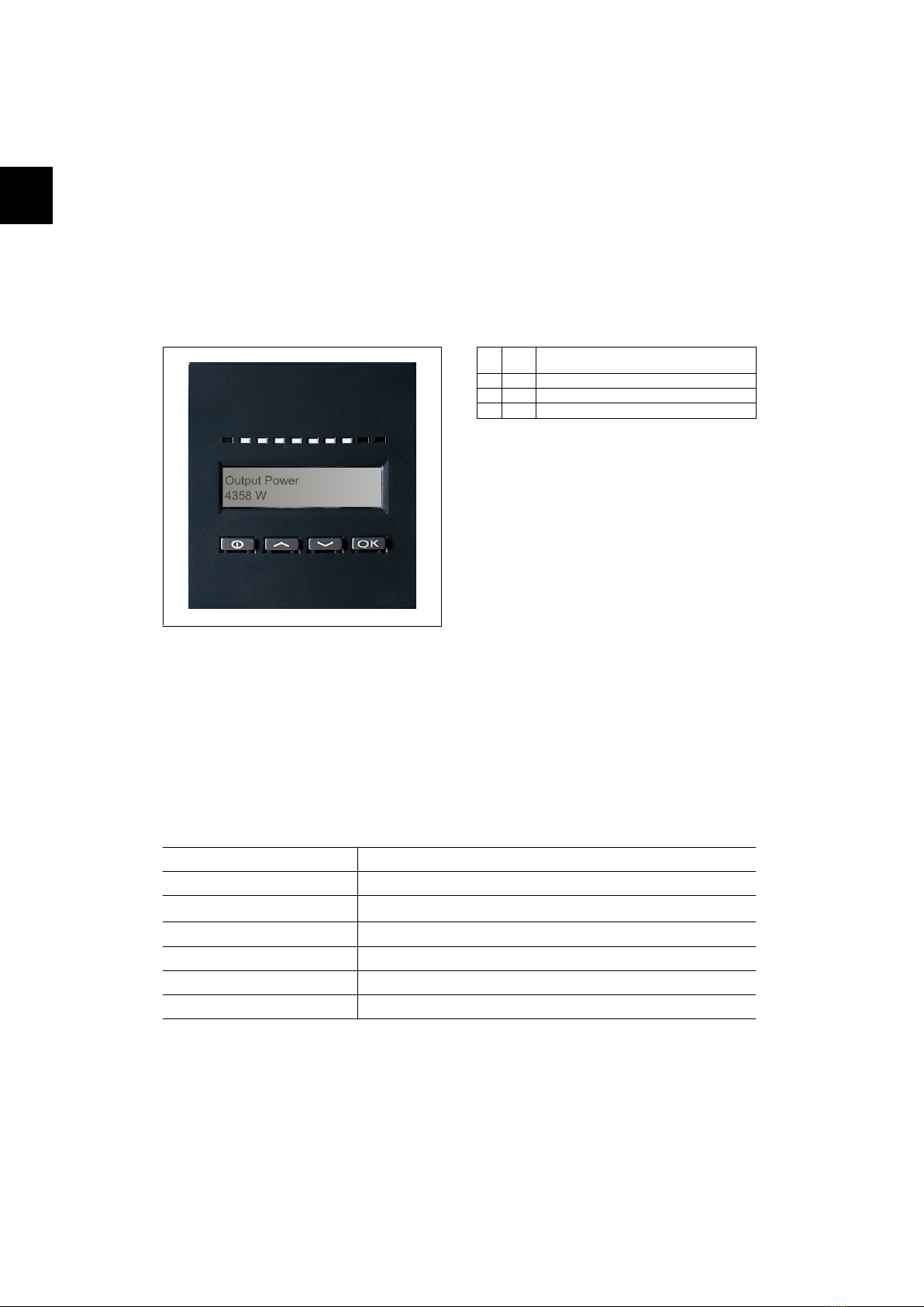
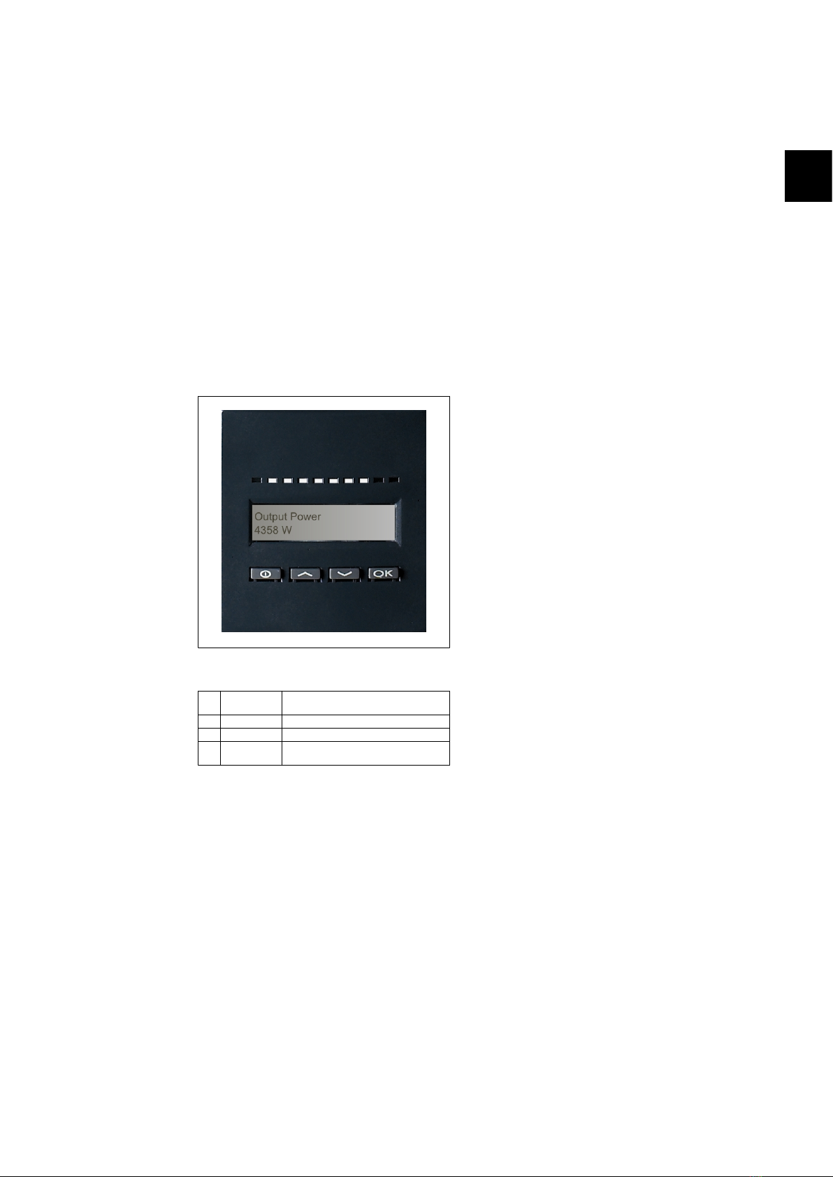
2.1.4. Display
Through the integrated display on the inverter front, the user has access to all information about
the PV system and the inverter. When the inverter is in OFF mode (at night), the inverter can be
activated by pressing the left button (ESC).
Illustration 2.2: Display
θ
ESC Goes one step backwards/up in the menu
structure
▲
Up Scrolls back to the previous menu display
▼
Down Scrolls forward to the next menu display
OK
Enter New menu level or changing of settings
The parameters shown in the display refer to
internally measured voltages and currents.
The parameters shown may deviate.
The display information is organised in a menu
structure divided into two sections: A and B
Section A: Contains information about the in-
verter and PV system performance.
Section B: Displays all measurement values
and user settings.
2.1.5. Overview Menu Section A
The table below gives an overview of the menu structure. The values shown are only intended as
examples of display texts. The display text (shown in the first column Display Functions ) is divided
between 2 lines, with 16 characters available per line. The line division is illustrated with the symbol
|.
Menu Structure A
Display Functions Description
Output power | 0 W Current output power in watt.
Inverter name | Use Service Tool to enter inverter name. If the inverter name is undefined this menu
is skipped.
Total production | 22.991 kWh Total energy production in kWh since first inverter start-up.
Total operating time | 00028h 57m 02s Total operating time (time with power on) displayed in hours, minutes and seconds.
Production today | 19637 Wh Energy production today in Wh.
Go to menu B Jumps to menu level B when OK is pressed.
Table 2.2: Overview Menu Structure A
2. Function Description
6L00410353-02
2
2.1.6. Overview Menu Section B
The table below gives an overview of the menu structure. The two menu levels are clearly indicated
by an arrow followed by a submenu. The values shown are only intended as examples of display
texts.
The display text (shown in the first column Display Functions ) is divided between 2 lines, with 16
characters available per line. The line division is illustrated with the symbol |.
Menu Structure B
Display Functions Description
Operation mode | STANDBY Displays present inverter operation mode. See operation mode definitions
in chapter 2.
PV configuration | IDLE Shows the status of the automatic PV configuration test and the results
found.
Event: Mod. | ENS FL. CH DCAC If the inverter is not connected to the grid because of a failure, the red
LED starts flashing, and the reason for the failure is shown here.
Language | ENGLISH View and choose display language. Does not affect any other settings.
Grid voltage | 0 V Displays the present grid AC voltage.
Grid current | 0.00 A Displays the present current flow to the grid.
Grid frequency | 0.00 Hz Displays the present grid frequency.
Grid impedance | 0.0 ohm Displays the present grid impedance.
PV voltage | Press OK to view Press OK to access submenu for recorded events.
↳Submenu
PV voltage no. 1 | 303.0 V Present voltage at PV input 1 (upper position in inverter).
PV voltage no. 2 | 303.0 V Present voltage at PV input 2 (second position in inverter)*.
PV voltage no. 3 | 303.0 V Present voltage at PV input 3 (third position in inverter)*.
PV current | PRESS OK to view Press OK to access submenu for recorded events.
↳Submenu
PV current no. 1 | 0.0 A Present current at PV input 1 (upper position in inverter).
PV current no. 2 | 0.0 A Present current at PV input 2 (second position in inverter)*.
PV current no. 3 | 0.0 A Present current at PV input 3 (third position in inverter)*.
Maximum values | Press OK to view Press OK to access submenu for recorded events.
↳Submenu
AC out: 1844 W | 8.356 A 263 V Maximum values recorded at AC output since last resetting of max. value
memory. (reset)
DC1 in: 2220 W** | 8.004 A 509 V Maximum values recorded at DC1 input since last resetting of max. value
memory. (reset).
DC2 in: 2220 W** | 8.004 A 509 V Maximum values recorded at DC2* input since last resetting of max. value
memory. (reset)
DC3 in: 2220 W** | 8.004 A 509 V Maximum values recorded at DC3* input since last resetting of max. value
memory. (reset)
Table 2.3: Overview Menu Structure B
*) The PV2 and PV3 menus are only displayed in inverters equipped with two or three inputs.
**) The maximum values for PV power may reach more than 2000 W in inverters where the inputs are connected in parallel.
This is normal.
2. Function Description
L00410353-02 7
2

Menu Structure B- Continued
Display Functions Description
Total drt. Temp. - Press OK to view Total Derating Temperature. Shows the total amount of time the inverter
has derated due to high temperature.
↳Submenu
DC1 derate temp. | 3h 35m DC1 Derating Temperature. Shows the amount of time the inverter has
derated due to high temperature.
DC2 derate temp. | 3h 35m DC2 Derating Temperature. Shows the amount of time the inverter has
derated due to high temperature.
DC3 derate temp. | 3h 35m DC3 Derating Temperature. Shows the amount of time the inverter has
derated due to high temperature.
Total drt. Grid | 0h 00 min Total Derating Grid. Shows the amount of time the inverter has derated
due to unstable grid conditions.
Power-down time | 00600 seconds Time before inverter goes into ‘OFF’ mode when no solar power is available.
Code numbers | PRESS OK to view Press OK to access submenu for recorded events.
↳Submenu
Inverter code no. | Indicates inverter product code.
AC code number | C0070105602 Indicates AC module product code.
DC1 code number | C0070105402 Indicates DC1 module product code.
DC2 code number | C0070105402 Indicates DC2* module product code.
DC3 code number | C0070105402 Indicates DC3* module product code.
Serial numbers | Press OK to view Press OK to go to submenu for recorded events.
↳Submenu
Inverter SN: | Indicates inverter serial number.
AC SN: | 117500C0408 Indicates AC module serial number.
DC1 SN: | 642800C0808 Indicates DC1 module serial number.
DC2 SN: | 642800C0808 Indicates DC2* module serial number.
DC3 SN: | 642800C0808 Indicates DC3* module serial number.
Table 2.4: Overview Menu Structure B
*) The PV2 and PV3 menus are only displayed in inverters equipped with two or three inputs.
In menu section A the display will continue to show the menu point last chosen by the user.
In menu B the display automatically switches to menu A when there has been no keyboard activity
for 3 minutes.
If the inverter is off grid and no keys have been pressed for a certain number of seconds, the
display will automatically switch to the operation mode display.
If the inverter is on grid and there has been no keyboard activity for 3 minutes, the display au-
tomatically switches to the display Production today. When the PV configuration test initiates and
terminates the display temporarily changes to menu B to show the state of the PV configuration
test.
If the inverter is disconnected from the grid because of a failure, the red LED will start flashing,
and the display automatically switches to menu B, where the event is shown.
2. Function Description
8L00410353-02
2

If an earthing fault occurs, the display will indicate this by a flash of the lit green LEDs. The display
will change to “current event”, if it has not been operated in the past 10 minutes. The inverter
will continue to produce energy. In case an earth fault occurs, this does not indicate an inverter
error and technical assistance must be called to check the PV panel connection.
Only applicable if earth fault detection is enabled. By default, earth fault detection is enabled for
the following countries: Austria, France and Spain.
2. Function Description
L00410353-02 9
2

3. Troubleshooting
3.1. Troubleshooting
Note:
Remember that only trained and authorised personnel familiar with electrical systems and
safety issues may work on inverters and electrical installations.
In the following, the term 'Event' describes all events that prevent the inverter from operating
properly.
An event may occur anywhere in the installation (grid, PV module, cable and connections, inverter)
at any time. Not all events indicate an inverter error.
If the PV system does not supply power to the grid as expected, please go through the following
checklist:
1. Check that the grid is connected properly to the inverter and that the grid is ready for
operation.
2. Check that there is sufficient solar radiation to generate power.
3. Check for shading and loose cables/connections in the PV system.
4. Check the installation of the PV modules if the voltages of the PV modules is not within
the expected values.
5. Check the event in menu B. If the red LED is flashing, this indicates a failure.
6. If the above-mentioned points are OK, wait 15 minutes to find out whether there is a
permanent failure.
7. If the PV system still does not supply any power to the grid, please check the voltage,
current and power of the PV module as well as voltage, current and power of the grid in
menu B.
8. If the voltage values of the grid do not lie within the threshold values, please contact
your public utility for technical assistance.
3.1.1. Inverter Event Messages
Event: Mod.
U-GRID DCAC
The red LED will start flashing in case of an
inverter event. Please check the event in
menu B.
The event text is a short text describing the event. If the inverter reports an event ID number to
the display instead of a text, no event text has been predefined for that particular event ID num-
ber. This could be the case if the display software is older than the inverter software. Module
designation identifies the module that caused the event (DC1, DC2, DC3 or AC).
3. Troubleshooting
10 L00410353-02
3

Event text Description Fault
origin Action in the event of a permanent fail-
ure
U 3.3 Internal power supply outside limits Inverter Service inverter
U 5.0 Internal power supply outside limits Inverter Service inverter
U 15.0 Internal power supply outside limits Inverter Service inverter
U PV Input voltage from PV string too high PV system Request technical service from PV system
supplier
U-SNUBBER Snubber voltage too high Inverter Service inverter
U DC-BUS DC bus voltage too high Inverter Service inverter
U-GRID AC grid voltage outside the threshold
values (higher or lower than setting) AC grid In case of repeated occurrence: Request
technical service from utility
F-GRID Grid frequency outside limits (outside
settings) AC grid In case of repeated occurrence: Request
technical service from utility
IPM CURRENT The DC content in the AC current is too
high Inverter Service inverter
ENS ENS error AC grid In case of repeated occurrence: Request
technical service from utility
ENS RAM ENS memory error Inverter Service inverter
ENS FL. CHKSM Flash memory error after self-test Inverter Service inverter
ENS EP. CHKSM EPROM memory error after self-test Inverter Service inverter
HW TRIP Hardware trip – current too high Inverter Service inverter
TEMP HIGH Temperature in integrated power mod-
ule too high Environ-
ment Check whether inverter is covered.
Check inverter for free air flow through heat
sink. Clean heat sink.
Check that ambient temperature is within
limits.
EPRM PAR. LIM Validity check of grid voltage and fre-
quency settings. Settings too far away
from actual grid voltage and frequency
values.
Inverter Request service to check inverter settings
ENS COM ERR Error in communication with ENS board Inverter Service inverter
ENS impedance Grid impedance step higher than limit AC grid In case of repeated occurrence: Request
technical service from utility
PV—CONFIG—ERR Error detected by PV configuration test PV system Check the cabling of the PV panels. Two DC
inputs are wired in parallel string configura-
tion, one is not
Not recorded in the event log - red LED does not flash
Event text Description Fault
origin Action in the event of a permanent fail-
ure
EARTHFAULT Current event shown in grid mode PV system Earth fault, check PV system for earthing to
avoid damage to PV panels. Request techni-
cal service from the PV system supplier or in-
staller.
Table 3.1: Inverter Event Log
A “permanent failure” is defined by an event having been present for more than 15 minutes.
3. Troubleshooting
L00410353-02 11
3

4. Maintenance
4.1. Maintenance
Normally, the TRI-Xi outdoor inverters need no maintenance or calibration. It should be ensured,
however, that the cooling is not obstructed.
To ensure the functionality of the DC-switch (optional), all switches should be switched on and
off (by turning the switch to on and off positions ten times), once a year, to clean the contacts.
4.1.1. Cleaning the Cabinet
Clean inverter by means of pressurised air or a soft cloth or a brush. Do not use a water hose,
aggressive chemicals, cleaning solvents or strong detergents to clean the inverter.
4.1.2. Cleaning the Heatsink
In order to secure proper function and long inverter life, it is essential that the free air circulation
around the heatsink at the back of the inverter and by the fan at the bottom of the inverter is not
obstructed. If the free air circulation is obstructed, e.g. by dust, this has to be removed. Clean the
heatsink by means of pressurised air or a soft cloth or a brush. Do not use a water hose, aggressive
chemicals, cleaning solvents or strong detergents to clean the inverter.
The heatsink can reach a temperature of more than 70°C during operation. Touching
components of this temperature may result in serious injuries!
Note:
Do not cover the inverter.
4. Maintenance
12 L00410353-02
4

Inhaltsverzeichnis
1. Einführung 14
2. Funktionsbeschreibung 15
Definition der Betriebsarten 15
PV Konfiguration 15
LEDs 16
Display 17
Überblick Menübereich A 18
Überblick Menübereich B 19
3. Fehlerbehebung 22
Fehlerbehebung 22
Wechselrichter – Ereignismeldungen 22
4. Wartung 24
Wartung 24
Reinigen des Schaltschranks 24
Reinigen des Kühlkörpers 24
Inhaltsverzeichnis
L00410353-02 13
1. Einführung
1.1. Einführung
Dieses Handbuch beschreibt die photovoltaischen Wechselrichter von TRITEC. Diese Produkte
zählen zu den technologisch fortschrittlichsten und effizientesten Wechselrichtern auf dem Markt
und ermöglichen eine verlässliche Versorgung mit Solarenergie über viele Jahre hinweg.
Abbildung 1.1: TRI-Xi-Modelle für den Außenbereich – mit Display
CE-Kennzeichnung: Diese Kennzeichnung gibt an, dass die Geräte den gel-
tenden Vorschriften der Richtlinien 2004/108/EC und 2006/95/EC entspre-
chen.
1. Einführung
14 L00410353-02
1

2. Funktionsbeschreibung
2.1. Definition der Betriebsarten
Der Wechselrichter hat vier Betriebsarten:
Betriebsart Standby:
In der Betriebsart Standby ist der Wechselrichter bereit, auf den Anschlussmodus umzuschalten.
Als Entscheidungsgröße wird die Eingangsspannung des PV-Generators herangezogen. Übersteigt
die Eingangsspannung einen definierten Sollwert, wechselt der Wechselrichter aus der Betriebsart
Standby in den Anschlussmodus oder leitet bei Verringerung der PV-Spannung in die Betriebsart
„AUS“ über.
Anschlussmodus:
Nach Durchführung der Systemprüfungen, bei denen geprüft wird, ob alle Anschlussbedingungen
erfüllt sind, geht der Wechselrichter von der Betriebsart Standby in den Anschlussmodus über.
Der Wechselrichter fährt während der vorgegebenen Aufschaltzeit mit der Prüfung der System-
werte fort und verbindet, soweit die Systemprüfungen erfolgreich sind, den Wechselrichter mit
dem Netz. Die minimale Aufschaltzeit ist von den Versorgungsunternehmen und Behörden vor-
gegeben und kann von Region zu Region unterschiedlich sein.
Netzbetrieb:
Bei dieser Betriebsart ist der Wechselrichter mit dem Netz verbunden und liefert Strom ins Netz.
Der Wechselrichter wird nur bei einer abnormalen Netzbedingung oder bei fehlender PV-Leistung
vom Netz abgekoppelt.
Aus:
Ist kein PV-Strom zur Versorgung des Wechselrichters vorhanden, wartet der Wechselrichter zehn
Minuten (vorgegebener Wert), bevor er abschaltet. In dieser Betriebsart ist die Stromversorgung
zu allen Prozessoren abgeschaltet, um Strom zu sparen. Das ist der normale Nachtbetrieb.
2.1.1. Netzüberwachung
Um an Leistungskabeln arbeitendes Personal und den Wechselrichter zu schützen, schaltet der
Wechselrichter bei abnormalem Netzverhalten oder Netzausfall ab. Der Wechselrichter überwacht
über einen internen Prüfstrang ständig die Netzspannung und -frequenz. Daher stellt der Wech-
selrichter die Verbindung wieder her, wenn sich die Netzwerte wieder innerhalb der Grenzwerte
befinden.
2.1.2. PV Konfiguration
Bei Anschluss an das Netz führt der Wechselrichter eine automatische Prüfung der PV-Modul-
verdrahtung durch. Diese Prüfung bestimmt die Verdrahtungskonfiguration der Module. Es wird
ermittelt, ob die Module in Individualmodus-Konfiguration oder Parallelstrang-Konfiguration an-
geschlossen sind, und der Wechselrichter wird automatisch entsprechend konfiguriert.
Die Prüfung aktiviert nacheinander jeden Eingang. Sie nimmt 1 - 2 Minuten in Anspruch, und der
Wechselrichter erzeugt dabei weiterhin Energie.
2. Funktionsbeschreibung
L00410353-02 15
2
Für TRI-Xi 5.4 müssen zwei von drei DC-Modulen für den Test mit Strom versorgt werden. Steht
nicht genügend PV-Energie zur Versorgung von zwei Modulen zur Verfügung, wird die Prüfung
verschoben, bis genügend PV-Energie für den Betrieb des zweiten DC-Moduls vorliegt.
Für Wechselrichtern mit Dislpaly kann das Prüfergebnis im Displaymenü B für die PV-Konfiguration
abgelesen werden. Nach Abschluss der Prüfung zeigt das Display automatisch die erkannte PV-
Konfiguration, allerdings nur, wenn die Tasten am Display in den letzten 3 Minuten nicht betätigt
wurden.
Abbildung 2.1: PV-Konfigurationsprüfung
Die Displayanzeige zeigt den Prüfstatus. Die
erste Zeile zeigt, dass dies die PV-Konfigura-
tion betrifft, und die zweite Zeile zeigt den
Status der Prüfung oder die erkannte Konfi-
guration.
Das Statusfeld kann Folgendes zeigen:
Angezeigter
Text
Beschreibung
LEERLAUF Die PV-Konfigurationsprüfung wurde noch nicht ausgeführt. Dies wird vor
dem Anschluss des Wechselrichters an das Netz gezeigt.
OFF PV-Konfigurationstest deaktiviert. Gilt für TRI-Xi 1.8 und für Wechselrichter,
bei denen der Test ansonsten deaktiviert ist.
WARTEN Die PV-Konfigurationsprüfung ist betriebsbereit, es ist jedoch nur genügend
Einstrahlung für einen PV-Eingang verfügbar. (Gilt für TRI-Xi 5.4 . Der Wech-
selrichter kann nur die Konfiguration aller drei Module bestimmen, wenn zwei
von ihnen laufen.)
PV-AUTOERKEN-
NUNG
Der PV-Konfigurationstest wird ausgeführt. Es liegt jedoch noch kein Ergebnis
vor.
INDIVUDUELL Die PV-Module sind in Individualmodus-Konfiguration angeschlossen.
PARALLEL 1-2* Die PV-Konfiguration ist beendet und hat ergeben, dass die Eingänge 1 und
2 in Parallelstrangkonfiguration angeschlossen sind.
PARALLEL 1-3* Die PV-Konfiguration ist beendet und hat ergeben, dass die Eingänge 1 und
3 in Parallelstrangkonfiguration angeschlossen sind.
PARALLEL 2-3* Die PV-Konfiguration ist beendet und hat ergeben, dass die Eingänge 2 und
3 in Parallelstrangkonfiguration angeschlossen sind.
PARALLEL 1-2-3 Die PV-Konfiguration ist beendet und hat ergeben, dass die Eingänge 1, 2 und
3 in Parallelstrangkonfiguration angeschlossen sind.
Tabelle 2.1: Text im Statusfeld zur PV-Konfigurationsprüfung
*) „PARALLEL 1-2“ ist nur für den Wechselrichter TRI-Xi 3.6 zulässig. „PARALLEL 1-2“, „PARALLEL
1-3“ und „PARALLEL 2-3“ ist für den Wechselrichter TRI-Xi 5.4 nicht zulässig.
2.1.3. LEDs
Die grünen LED-Anzeigen geben die Produktion in Prozent der Nennleistung des Wechselrichters
an.
2. Funktionsbeschreibung
16 L00410353-02
2
Die ganz links befindliche grüne LED leuchtet immer auf, wenn der Wechselrichter mit dem Netz
verbunden ist. Während der Netzanschluss hergestellt wird, leuchten sowohl die rote LED als auch
die grüne LED ganz links. Wenn der Wechselrichter vom Netz getrennt ist, leuchtet die rote LED
links zur Anzeige, dass sich der Wechselrichter im Bereitschaftsmodus befindet. Es leuchten keine
grüne LEDs. Wenn keine LEDs leuchten, ist der Wechselrichter ausgeschaltet. Befindet sich der
Wechselrichter aufgrund eines Ereignisses im Wechselrichter oder der peripheren Anschlüsse, z.
B. einem Netzabwurf, zwangsweise im Bereitschaftsmodus, beginnt die rote LED zu blinken.
Eine Beschreibung der Ereignisse enthält der Abschnitt
Fehlerbehebung
.
2.1.4. Display
Der Benutzer hat über das integrierte Display auf der Vorderseite des Wechselrichters Zugang zu
allen Informationen über das PV-System und den Wechselrichter. Befindet sich der Wechselrichter
im OFF-Betrieb (bei Nacht), ist es möglich, den Wechselrichter durch eine Betätigung der linken
Taste (ESC-Taste) am Display zu aktivieren.
Abbildung 2.2: Display
θ
ESC Einen Schritt zurück/nach oben in der
Menüstruktur
▲
Nach oben Blättert zum vorherigen Menü
▼
Nach unten Blättert zum nächsten Menü
OK
Eingabetaste Neue Menüebene oder Änderung der
Einstellungen
Die angezeigten Parameter im Display bezie-
hen sich auf intern gemessene Spannungen
und Ströme. Die angezeigten Parameter kön-
nen Abweichungen aufweisen.
Die Display-Informationen sind in einer in zwei
Bereiche unterteilten Menüstruktur organi-
siert: A und B
Abschnitt A: Enthält Informationen über die
Wechselrichter- und PV-Systemleistung.
Abschnitt B: Zeigt alle Messwerte und Benut-
zereinstellungen an.
2. Funktionsbeschreibung
L00410353-02 17
2

2.1.5. Überblick Menübereich A
Die nachfolgende Tabelle bietet einen Überblick der Menüstruktur. Die angegebenen Werte dienen
nur als Beispiel für die Displaytexte. Der Displaytext (siehe erste Spalte „Displayfunktionen“) wird
auf zwei Zeilen à 16 Zeichen angezeigt. Der Zeilenumbruch ist durch das Symbol | gekennzeichnet.
Menüstruktur A
Displayfunktionen Beschreibung
Ausgangsleistung | 0 W Aktuelle Ausgangsleistung in Watt.
Wechselr. Name Verwenden Sie das Service Tool zur Eingabe des Wechselrichternamens. Wenn der Name
des Wechselrichters nicht definiert ist, wird dieses Menü übersprungen.
Energie gesamt | 22.991 kWh Gesamte Energieerzeugung in kWh seit Start des Wechselrichters.
Betriebsdauer | 00028h 57m 02s Die gesamte Betriebsdauer (Zeit der Stromeinspeisung) wird in Stunden, Minuten und
Sekunden angezeigt.
Energie heute | 19637 Wh Energieerzeugung von heute in Wh.
Menü B wählen Springt nach Betätigung von OK zu Menüebene B.
Tabelle 2.2: Überblick Menüstruktur A
2. Funktionsbeschreibung
18 L00410353-02
2

2.1.6. Überblick Menübereich B
Die nachfolgende Tabelle bietet einen Überblick der Menüstruktur. Die beiden Menüebenen wer-
den durch einen Pfeil gekennzeichnet, dem ein Untermenü folgt. Die angegebenen Werte dienen
nur als Beispiel für die Displaytexte.
Der Displaytext (siehe erste Spalte „Displayfunktionen“) wird auf zwei Zeilen à 16 Zeichen ange-
zeigt. Der Zeilenumbruch ist durch das Symbol | gekennzeichnet.
Menüstruktur B
Displayfunktionen Beschreibung
Betriebsart | STANDBY Zeigt die aktuelle Betriebsart des Wechselrichters an. Siehe Definitionen der
Betriebsarten in Kapitel 2.
PV-Konfiguration | LEERLAUF Zeigt den Status der automatischen PV-Konfigurationsprüfung und ermittelte
Ergebnisse an.
Event Modul | ENS FL. CH DCAC Ist der Wechselrichter aufgrund einer Störung nicht am Netz angeschlossen,
blinkt die rote LED, und die Störungsursache wird hier angezeigt.
Sprache | DEUTSCH Anzeige und Auswahl der Displaysprache. Hat keinen Einfluss auf andere
Einstellungen.
Netzspannung | 0 V Zeigt die aktuelle AC-Netzspannung an.
Netzstrom | 0.00 A Zeigt den aktuell in das Netz fließenden Strom an.
Netzfrequenz | 0.00 Hz Zeigt die aktuelle Netzfrequenz an.
Netzimpedanz | 0.0 ohm Zeigt die aktuelle Netzimpedanz an.
PV Spannung | OK drücken Die Taste „OK“ drücken, um zum Untermenü für protokollierte Ereignisse zu
gelangen.
↳Untermenü
PV Spannung Nr. 1 | 303.0 V Aktuelle Spannung am PV-Eingang 1 (obere Position im Wechselrichter).
PV Spannung Nr. 2 | 303.0 V Aktuelle Spannung am PV-Eingang 2 (zweite Position im Wechselrichter)*.
PV Spannung Nr. 3 | 303.0 V Aktuelle Spannung am PV-Eingang 3 (dritte Position im Wechselrichter)*.
PV Strom | OK drücken Die Taste „OK“ drücken, um zum Untermenü für protokollierte Ereignisse zu
gelangen.
↳Untermenü
PV Strom Nr. 1 | 0.0 A Aktueller Strom am PV-Eingang 1 (obere Position im Wechselrichter).
PV Strom Nr. 2 | 0.0 A Aktueller Strom am PV-Eingang 2 (zweite Position im Wechselrichter)*.
PV Strom Nr. 3 | 0.0 A Aktueller Strom am PV-Eingang 3 (dritte Position im Wechselrichter)*.
Maximalwerte | OK drücken Die Taste „OK“ drücken, um zum Untermenü für protokollierte Ereignisse zu
gelangen.
↳Untermenü
AC: 1844 W | 8.356 A 263 V Maximalwerte gemessen am AC-Ausgang seit der letzten Rückstellung des
Maximalwertspeichers. (Rückstellung)
DC1: 2220 W** | 8.004 A 509 V Maximalwerte gemessen am DC1-Eingang seit der letzten Rückstellung des
Maximalwertspeichers. (Rückstellung)
DC2: 2220 W** | 8.004 A 509 V Maximalwerte gemessen am DC2*-Eingang seit der letzten Rückstellung des
Maximalwertspeichers. (Rückstellung)
DC3: 2220 W** | 8.004 A 509 V Maximalwerte gemessen am DC3*-Eingang seit der letzten Rückstellung des
Maximalwertspeichers. (Rückstellung)
Tabelle 2.3: Überblick Menüstruktur B
*) Die PV2- und PV3-Menüs kommen nur in mit zwei oder drei Eingängen ausgestatteten Wechselrichtern zur Anzeige.
**) Die Maximalwerte für PV-Leistung können mehr als 2000 W erreichen, wenn die Eingänge parallel verbunden sind. Dies
ist normal.
2. Funktionsbeschreibung
L00410353-02 19
2
This manual suits for next models
2
Table of contents
Languages:
Popular Inverter manuals by other brands

Westerbeke
Westerbeke 10.0 EGTD Operator's manual

Prudent Way
Prudent Way PWI-IV150-BL user manual

Silverline
Silverline 868853 user manual

TOMMATECH
TOMMATECH Trio-Hybrid K Series manual

Afore
Afore HNS3000TL Installation and operation manual

Mitsubishi Electric
Mitsubishi Electric melpto d series Operation manual


