AEG AGN6500 User manual


2
2
Axle
Wheel
Flat
Washer
Hitch Pin
Screw, 2 in.
Flat Washer
Frame support
with foot
Lock Nut
Lock Nut
Flat Washer
Frame
Frame
crossbar
Screw, 1 in.
Engine Switch
AC Breaker
DC Breaker
Key Starter
Fuel Tank
Oil Drainage Bolt
Fuel Cap
Choke Lever
Fuel Valve
Oil Light
Air Filter
Recoil Starter Grip
Carburetor
Drain Screw
Fig. 1
Fig. 5
Fig. 3
Fig. 2
Fig. 4

33
Fuel Tank
Fuel Cap
Extension Cord
Oil Cap / DipstickOil Cap / Dipstick
Oil Fill HoleOil Fill Hole
108 mm
(4-1/4 in.)
16 mm(5/8 in.)
6 mm(1/4 in.)
Fig. 7
Fig. 6
Fig. 10 Fig. 11
Fig. 8 Fig. 9

4
4
Spark Plug
Spark Plug Cap
Filter Elements
Air Filter
Cover
Bolt
Bolt
Recoil
Starter Grip
Twist-lock Receptacle Extension Cord
Twist-lock Plug
Choke Lever
To Run
(Choke open)
To Start
(Choke closed)
OFF
ON
Fuel ValveFuel Valve
FilterFilter
Fig. 17
Fig. 13
Fig. 14 Fig. 15
Fig. 16
Fig. 12

55
INTRODUCTION
This product has many features for making its use more pleasant
and enjoyable. Safety, performance, and dependability have
been given top priority in the design of this product, making it
easy to maintain and operate.
DANGER
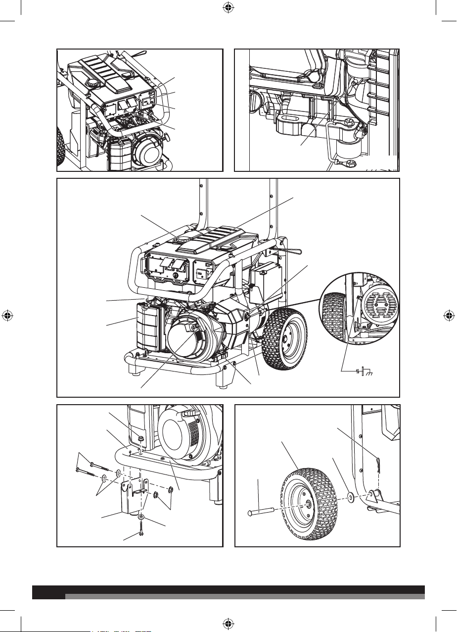
Grounding the Generator
See Figure 3.
In Australia and New Zealand, grounding of portable
generators is not recommended or required. Consult with
local electricians to determine grounding requirements
before operating with a ground connection.
GENERAL SAFETY RULES
WARNING:
Read and understand all instructions. Failure to follow
all instructions listed below may result in electrocution,
fire, and/or carbon monoxide poisoning, which will cause
death or serious injury.
WARNING:
When this generator is used to supply a building
wiring system: the generator must be installed by a
qualified electrician and connected to a transfer switch as
a separately derived system in accordance with Australian
Wiring Rules. The generator shall be connected through
a transfer switch that switches all conductors other than
the equipment grounding conductor. The frame of the
generator shall be connected to an approved grounding
electrode. Failure to isolate the generator from power
utility can result in death or injury to electric utility workers.
Save these instructions
This manual contains important instructions that should be
followed during installation and maintenance of the generator
and batteries.
ŶDo not allow children or untrained individuals to use this
unit.
ŶNever start or run the engine inside a closed or partially
enclosed area. Breathing exhaust fumes will kill you.
ŶWear eye protection as well as hearing protection when
operating this equipment.
ŶKeep all bystanders, children, and pets at least 3 m away.
ŶWear sturdy and dry shoes or boots. Do not operate while
barefoot.
ŶDo not operate the generator when you are tired or under
the influence of drugs, alcohol, or medication.
ŶKeep all parts of your body away from any moving parts
and all hot surfaces of the unit.
ŶProduct users in some areas are required to comply with
fire prevention regulations. Check with the local authorities
in your area before use.
ŶDo not touch bare wire or receptacles.
ŶDo not use the generator with electrical cords which are
worn, frayed, bare, or otherwise damaged.
ŶBefore storing, allow the engine to cool.
ŶDo not operate the generator in rain, snow, or wet weather
ŶEmpty fuel tank, close fuel valve, and restrain the unit from
moving before transporting in a vehicle.
ŶAllow engine to cool for five minutes before refueling.
ŶTo reduce the risk of fire and burn injury, handle fuel with
care. It is highly flammable.
ŶDo not smoke while handling fuel.
ŶStore fuel in a container approved for unleaded fuel.
ŶPosition the unit on level ground, stop engine, and allow to
cool before refueling.
ŶLoosen fuel cap slowly to release pressure and to keep fuel
from escaping around the cap.
ŶTighten the fuel cap securely after refueling.
ŶWipe spilled fuel from the unit.
ŶNever attempt to burn off spilled fuel under any
circumstances.
ŶUse only authorised replacement parts and accessories
and follow instructions in the Maintenance section of this
manual. Use of unauthorised parts or failure to follow
Maintenance instructions may create a risk of shock or
injury.
ŶMaintain the unit per maintenance instructions in this
Operator’s Manual.
ŶInspect the unit before each use for loose fasteners, fuel
leaks, etc. Replace damaged parts.
ŶGenerators vibrate in normal use. During and after the use
of the generator, inspect the generator as well as extension
cords and power supply cords connected to it for damage
resulting from vibration. Have damaged items repaired or
replaced as necessary. Do not use plugs or cords that show
signs of damage such as broken or cracked insulation or
damaged blades.
SPECIFIC SAFETY RULES
ŶExhaust contains poisonous carbon monoxide, a
colourless, odourless gas. Breathing exhaust can cause
loss of consciousness and can lead to death. If the
generator is running in a confined or partially-enclosed
area, the air may contain a dangerous amount of carbon
monoxide. To keep exhaust fumes from building up, always
provide adequate ventilation.
ŶAlways use a battery-powered carbon monoxide detector
when running the generator. If you begin to feel sick, dizzy,
or weak while using the generator, shut it off and get to
fresh air immediately. See a doctor. You may have carbon
monoxide poisoning.
ŶPlace the generator on a flat, stable surface with a slope of
no more than 4°.
ŶOperate in a well-ventilated, well-lit area isolated from
working areas to avoid noise interference.
ŶOperating the generator in wet conditions could result in
electrocution. Keep the unit dry.
ŶKeep the generator a minimum of 1 m away from all types
of combustible material.
ŶDo not operate the generator near hazardous material.
ŶDo not operate the generator at a gas or natural gas filling
station.
ŶDo not touch the muffler or cylinder during or immediately
after use; they are HOT and will cause burn injury.

6
6
ŶDo not connect to a building’s electrical system unless a
transfer switch has been properly installed by a qualified
electrician.
ŶDo not allow the generator’s fuel tank to overflow when
filling. Fill to 25 mm below the top neck of the unleaded fuel
tank to allow for fuel expansion. Check the ventilation hole
inside the fuel tank cap for debris. Do not block the vent.
ŶDo not smoke when filling the generator with unleaded fuel.
ŶAllow the engine to remain in a shut-down condition for at
least five minutes before adding unleaded fuel or oil.
ŶDo not remove the oil dipstick or the fuel tank cap when the
engine is running.
ŶPay close attention to all safety labels located on the
generator.
ŶKeep children a minimum of 3 m (10 ft.) away from the
generator at all times.
ŶThe unit operates best in temperatures between 5°C and
40°C with a relative humidity of 30~95%.
ŶDo not operate the generator at altitudes above 1,000 m.
ŶWhen using extension lines or mobile distribution networks
the total length of lines for a cross section of 1.5 mm2
should not exceed 60 m; for a cross section of 2.5 mm2
this should not exceed 100 m.
ŶThe generating set must not be connected to other power
sources.
ŶSave these instructions. Refer to them frequently and use
them to instruct others who may use this tool. If you loan
someone this tool, loan them these instructions also.
SERVICE
Servicing requires extreme care and knowledge and should be
performed only by a qualified service technician. For service,
contact your nearest authorised service centre for repair. When
servicing, use only identical replacement parts.
WARNING:
Observe all normal safety precautions to avoid electrical
shock.
DANGER:
To avoid death or serious personal injury, do not attempt
to operate this product until you read thoroughly and
understand completely the operator’s manual. If you
do not understand the warnings and instructions in the
operator’s manual, do not use this product. Call your
nearest authorised service centre for assistance.
WARNING:
The operation of any products can result in foreign
objects being thrown into your eyes, which can result
in severe eye damage. Before beginning power tool
operation, always wear safety goggles or safety glasses
with side shields and, when needed, a full face shield.
We recommend Wide Vision Safety Mask for use over
eyeglasses or standard safety glasses with side shields.
Always wear eye protection.
Save these instructions
SYMBOLS
Some of the following symbols may be used on this tool. Please
study them and learn their meaning. Proper interpretation of
these symbols will allow you to operate the tool better and
safer.
SYMBOL DESIGNATION/EXPLANATION
V Voltage
A Current
Hz Frequency (cycles per second)
W Power
hrs Time
litre Volume
ml Volume
cc Volume
Do not expose to rain or use in damp
locations.
To reduce the risk of injury, the user
must read and understand the operator’s
manual before using this product.
Always wear safety goggles or safety
glasses with side shields and, as
necessary, a full face shield and hearing
protection when operating this product.
Precautions that involve your safety.
Failure to use in dry conditions and to
observe safe practices can result in
electric shock.
Running the generator gives off carbon
monoxide, an odorless, colorless, poison
gas. Breathing carbon monoxide can
cause nausea, fainting, or death.
Fuel and its vapours are extremely
flammable and explosive. Fire or
explosion can cause severe burns or
death.
To reduce the risk of injury or damage,
avoid contact with any hot surface.
Beware of electric shock level.
Fuel and its vapors are explosive and can
cause severe burns or death.
Consult with local electrician to
determine grounding requirements
before operation.
Add lubricant to full mark to start. Engine
will not start or will shut off if lubricant
is too low.

77
Turn the fuel valve to the on or off
position.
102 dB
77 dB
102 dB
77 dB
102 dB
77 dB
102 dB
77 dB
102 dB
77 dB
102 dB
77 dB
102 dB
77 dB
The guaranteed sound pressure level
(7m) is shown on this label by 77 dB. The
guaranteed sound power level is shown
on this label by 102 dB.
The following signal words and meanings are intended to
explain the levels of risk associated with this product.
SYMBOL SIGNAL MEANING
DANGER:
Indicates an imminently
hazardous situation, which,
if not avoided, will result in
death or serious injury.
WARNING:
Indicates a potentially haz-
ardous situation, which, if
not avoided, could result
in death or serious injury.
CAUTION:
Indicates a potentially haz-
ardous situation, which, if
not avoided, may result in
minor or moderate injury.
CAUTION:
(Without Safety Alert Sym-
bol) Indicates a situation
that may result in property
damage.
ELECTRICAL
GENERATOR CAPACITY
Make sure the generator can supply enough continuous
(running) and surge (starting) watts for the items you will power
at the same time. Follow these simple steps.
1. Select the items you will power at the same time.
2. Total the continuous (running) watts of these items. This is
the amount of power the generator must produce to keep
the items running. See the wattage reference chart at right.
3. Estimate how many surge (starting) watts you will need.
Surge wattage is the short burst of power needed to start
electric motor-driven tools or appliances such as a circular
saw or refrigerator. Because not all motors start at the
same time, total surge watts can be estimated by adding
only the item(s) with the highest additional surge watts to
the total rated watts from step 2.
Example:
Tool or
Appliance
Continuous
(Running)
Watts
Additional Surge
(Starting) Watts
CD Player 100 0
Space Heater 1800 0
Drill 1/2 HP 600 300
Light Bulb 75 0
2575 Total
Running Watts 300 Surge Watts
Total Continuous (Running) Watts 2575
Plus Additional Surge Watts +300
Equals Total Generator Output Required
(to start all items simultaneously)
2875
POWER MANAGEMENT
To prolong the life of the generator and attached devices, it
is important to take care when adding electrical loads to the
generator. There should be nothing connected to the generator
outlets before starting its engine. The correct and safe way
to manage generator power is to sequentially add loads as
follows:
1. With nothing connected to the generator, start the engine
as described later in this manual.
2. Plug in and turn on the first load, preferably the largest load
you have.
3. Permit the generator output to stabilise (engine runs
smoothly and attached device operates properly).
4. Plug in and turn on the next load.
5. Again, permit the generator to stabilise.
6. Repeat steps 4 and 5 for each additional load.
Never add more loads than the generator capacity. Take
special care to consider surge loads in generator capacity as
previously described.
CAUTION:
Do not overload the generator’s capacity. Exceeding the
generator’s wattage/amperage capacity can damage
the generator and/or electrical devices connected to it.
Tool or Appliance
Typical
Continuous*
(Running)
Watts
Typical Surge
(Starting)
Watts
Essentials
/LJKW%XOEí:DWW 75 75
Refrigerator/Freezer 700 2200
6XPS3XPSí+3 1050 2200
:DWHU:HOO3XPSí+3 1000 1500
Electric Water Heater 4000 4000
Heating/Cooling
)XUQDFH)DQí+3 800 2350
:LQGRZ$&í%78 1200 1800
Space Heater 1800 1800
Kitchen
0LFURZDYH2YHQí:DWW 1000 1000
Coffee Maker 1000 1000
(OHFWULF6WRYHí6LQJOH(OHPHQW 2100 2100
Toaster Oven 1200 1200
Family Room
VCR 100 100
CD/DVD Player 100 100
Stereo Receiver 450 450
&RORXU7HOHYLVLRQíLQ 500 500
Other
Security System 500 500
Curling Iron 1500 1500

8
8
Noise Level (4m) LpA dB (A) 82
Noise Level (7m) LpA dB (A) 77
Noise Level LwA dB (A) 102
RCD
Voltage (V) 240
Fault Current Rating (A) 25
Trip Current Rating (mA) 30
Trip Time Rating (s) 0.05
If any of the labels come off the unit or become hard to read,
contact the authorised service centre for replacement.
FEATURES
KNOW YOUR GENERATOR
See Figure 3.
The safe use of this product requires an understanding of the
information on the product and in this operator’s manual as
well as a knowledge of the project you are attempting. Before
use of this product, familiarise yourself with all operating
features and safety rules.
AC CIRCUIT BREAKER
The circuit breaker is provided to protect the generator against
electrical overload and can be used to turn the generator’s
electrical power on or off.
AIR FILTER
The air filter helps to limit the amount of dirt and dust drawn into
the unit during operation.
CHOKE LEVER
The choke lever is used when starting the engine.
ENGINE SWITCH
The engine switch is used in combination with the recoil starter
grip to start the generator. It is also used to turn the generator
off.
FUEL TANK
30 litres
FUEL VALVE
The flow of fuel through the generator is controlled by the
position of the fuel valve.
GROUND TERMINAL
The ground terminal is used to assist in properly grounding
the generator to help protect against electrical shock. Consult
with a local electrician for grounding requirements in your area.
OIL LIGHT
The oil light is an indicator for the oil level. When the oil level is
too low, the oil light will flash in red.
OIL DRAINAGE BOLT
When changing the engine oil, the oil drainage bolt is loosened
to allow old engine oil to be drained.
OIL CAP/DIPSTICK
Remove the oil fill cap to check and add oil to the generator
when necessary.
*DUDJH'RRU2SHQHUí+3 875 2350
Hair Dryer 1250 1250
DIY/Job Site
Quartz Halogen Work Light 1000 1000
$LUOHVV6SUD\HUí+3 600 1200
Reciprocating Saw 960 1400
(OHFWULF'ULOOí+3 600 900
&LUFXODU6DZíLQ 1400 2300
0LWUH6DZíLQ 1800 2900
3ODQHU-RLQWHUíLQ 1800 1800
7DEOH6DZ5DGLDO$UP6DZíLQ 2000 3000
$LU&RPSUHVVRUí+3 1600 4500
*Wattages listed are approximate. Check tool or appliance for actual wattage.
SPECIFICATIONS
Generator
Product Weight (kg) 115
Product dimensions
Width (mm) 800
Length (mm) 800
Height - Length-folded (mm) 700
Height - Length-open (mm) 1350
AC output
AC Frequency (Hz) 50
AC Output Voltage (V) 240
Rated AC Output (W) 5,200
Rated Current (A) 21.67
Circuit Breaker (A) 25
Power Factor 1.0
DC output
Volts 12
Amps 8.3
12V DC Circuit Breaker Circuit (A)
9.2
Engine
Engine Number Yamaha MZ360
Engine Type 4-Stroke; air-cooled
OHV; unleaded fuel
Bore x Stroke 85 x 63
Displacement (cc) 357
Starting System DC Start or Recoil
Fuel Type Regular unleaded fuel
Lubrication Oil SAE 10W-30
Engine Oil Volume (l) 1.1
Fuel Tank Capacity (l) 30
Full Load (h) 9
Half Load (h) 13
Uncertainty dB 2

99
RECEPTACLES
Your generator has the following single phase, 50 Hz outlets:
two 240 Volt AC, 15 Amp receptacle. These can be used for
operating appropriate appliances, electrical lighting, tools, and
motor loads.
RECOIL STARTER GRIP
The recoil starter grip is used (along with the engine switch) to
start the generator’s engine.
DC ADAPTER
The DC power adapter may only be used for powering 12 volt
rate appliance.
DC CIRCUIT PROTECTOR
The DC circuit protector automatically shuts off the circuit when
the DC output is overloaded or when there is a problem with
the connections between the appliance and the generator are
improper.
BATTERY
12 V, 12 AH battery is used for electric starting.
GenSmart MONITORING SYSTEM
The GenSmart monitoring system tracks usage and load
and alerts the operator when periodic engine maintenance is
recommended.
RESIDUAL CURRENT DEVICE (RCD)
A safety switch to disconnect power to the AC outlets if a
30 mA or greater current difference occurs between the active
and neutral. Press the test button after starting the generator
and closing the AC breaker and RCD. Both should trip off.
ASSEMBLY
UNPACKING
This product has not been shipped completely assembled.
Wheel and foot assembly are required.
ŶRemove one end of the box and carefully slide out the
generator and any accessories.
NOTE: The generator is heavy. If you must lift the unit out
of the box, get another person to help you and lift with your
legs, not your back.
ŶInspect the unit carefully to make sure no damage occurred
during shipping.
ŶDo not discard the packing material until you have carefully
inspected and satisfactorily operated the product.
ŶIf any parts are damaged or missing, please contact your
nearest authorised service centre for assistance.
PACKING LIST
Generator Spark plug wrench
Oil bottle/Oil funnel Wheels / Legs
Operator’s manual Fasteners
WARNING:
If any parts are damaged or missing do not operate this
product until the parts are replaced. Failure to heed this
warning could result in serious personal injury.
INSTALLING THE LEGS
See Figure 4.
ŶLocate the following items:
2 legs with rubber feet
6 flat washers
6 lock nuts
4 screws (51 mm (2 in.))
2 screws (25 mm (1 in.))
ŶRaise the front end of the generator, where the engine is
located, high enough to gain access to the frame bottom;
securely position props underneath to support.
ŶPosition a leg over the holes on each side of the frame
support.
ŶInsert each 51 mm (2 in.) screw through a flat washer and
insert the screws through the two holes in the frame and
the leg.
ŶFasten the screws by installing a self-locking nut over each
screw on the inside of the frame. Tighten the nut securely.
ŶInsert a 25 mm (1 in.) screw through a flat washer, the hole
in the frame crossbar, and then through the hole in the leg
tab.Install a self-locking nut and tighten to secure.
ŶRepeat with remaining leg.
INSTALLING THE WHEELS
See Figure 5.
Wheels are provided to assist in moving the generator to the
desired location and should be installed on the side opposite
the recoil starter.
ŶLocate the following items:
2 axles
2 washers (16 mm (5/8 in.))
2 hitch pins
2 wheels
CONNECTING BATTERY
The battery cables must be connected before the electric start
feature of the generator can be operated.
ŶConnect the red wire to the positive (+) terminal first, then
FRQQHFW WKH EODFN ZLUH WR WKH QHJDWLYH í WHUPLQDO XVLQJ
the bolts, nuts, and washers provided. Make sure all
connections are tight.
NOTE: Be careful not to short across the terminals when
installing. Shorting the terminals together can cause
sparks, damage to the battery or generator, or even burns
or explosions.
ŶCover the terminals with the rubber covers.
When removing the battery for replacement: remove the
nut and bolt first from the negative (black) post, then from
the positive (red) post, being careful not to short across the
terminals. Always abide by the safety warnings provided with
the battery. Remove the battery and dispose of according to
local and state regulations.
WARNING:
To reduce the risk of electrocution or explosion, do not
short circuit the battery terminals or charge in a sealed
container. Keep sparks and flame away.
WARNING:
Keep metal objects away from the battery terminals.
Metal objects can make a connection from one terminal
to another. Shorting the battery terminals together could
cause sparks, burns, or a fire.

10
10
REMOVABLE CONTROL PANEL
See Figure 6.
To detach the removable control panel from the generator:
ŶTurn off the generator.
ŶLoosen the latch on the removable control panel and pull
the control panel forward.
ŶDisconnect the twist-lock plug and the 12V engine control
connector on the back of the control panel.
INSTALLING A WALL MOUNT FOR THE REMOVABLE
CONTROL PANEL
See Figures 7-8.
The removable control panel can be removed from the
generator and wall-mounted in another location before re-
connecting it to the generator.
To wall-mount the removable control box:
ŶScrews or nails for hanging the box should be spaced
108 mm (4-1/4 in.) from center to center.
ŶMark the 108 mm (4-1/4 in.) measurement on a wall stud or
other sturdy wood surface.
ŶDrill holes and insert the screws; tighten the screws
securely into the wood. If using nails, the nail head should
be large enough to hold the control panel securely.
NOTE: There should be at least 16 mm (5/8 in.) of the
screw or nails protruding from the wood piece for hanging
the box.
ŶHang the box on the screws or nails, making certain it is
secure.
WARNING:
Do not attempt to modify this tool or create accessories
not recommended for use with this tool. Any such
alteration or modification is misuse and could result in a
hazardous condition leading to possible serious personal
injury.
OPERATION
DANGER:
Carbon Monoxide. Using a generator indoors WILL KILL
YOU IN MINUTES.
Generator exhaust contains high levels of carbon monoxide
(CO), a poisonous gas you cannot see or smell. If you can
smell the generator exhaust, you are breathing CO. But even
if you cannot smell the exhaust, you could be breathing CO.
ŶNever use a generator inside homes, garages,
crawlspaces, or other partly enclosed areas. Deadly levels
of carbon monoxide can build up in these areas. Using
a fan or opening windows and doors does NOT supply
enough fresh air.
ŶONLY use a generator outdoors and far away from open
windows, doors, and vents. These openings can pull in
generator exhaust.
Even when you use a generator correctly, CO may leak into the
home. ALWAYS use a battery-powered or battery-backup CO
alarm in the home.
If you start to feel sick, dizzy, or weak after the generator has
been running, move to fresh air RIGHT AWAY. See a doctor.
You could have carbon monoxide poisoning.
WARNING:
Do not allow familiarity with tools to make you careless.
Remember that a careless fraction of a second is
sufficient to inflict serious injury.
WARNING:
Do not use any attachments or accessories not
recommended by the manufacturer of this product. The
use of attachments or accessories not recommended can
result in serious personal injury.
APPLICATIONS
This generator is designed to supply electrical power for
operating compatible electrical lighting, appliances, tools, and
motor loads.
BEFORE OPERATING THE UNIT
Position the generator on a flat surface before checking fluid
levels or adding fluid.
CAUTION:
Attempting to start the engine before it has been properly
filled with oil will result in equipment failure.
CHECKING/ADDING OIL
See Figure 9.
Engine oil has a major influence on engine performance and
service life. For general, all-temperature use, SAE 10W-30 is
recommended. Always use a 4-stroke motor oil that meets or
exceeds the requirements for API service classification SJ.
NOTE: Non-detergent or 2-stroke engine oils will damage the
engine and should not be used.
NOTE: The oil light will flash in red when the oil level is too low.
ŶUnscrew the oil cap/dipstick and remove.
ŶWipe dipstick clean and re-seat in hole; do not re-thread.
ŶRemove dipstick again and check oil level. Oil level should
fall within the level indicator area on the dipstick.
ŶIf level is low, add engine oil until the fluid level rises to
the upper portion of the level indicator area on the dipstick.
ŶReplace and secure the oil cap/dipstick.
CHECKING/ADDING FUEL
See Figure 10.
ŶStop the engine. Remove the fuel cap, check remaining
fuel. If fuel is needed, continue with next step.
ŶFill the fuel tank to 25 mm below the top of the fuel neck.
ŶReplace and secure the fuel cap.
NOTE: Always use unleaded gasoline with a pump octane
rating of 90 or higher. Never use old, stale, or contaminated
unleaded fuel, and do not use an oil/gas mixture. Do not allow
dirt or water into the fuel tank.
USING FUEL STABILISER
Fuel gets old, oxidizes, and breaks down over time. Adding a
fuel stabiliser extends the usable life of fuel and helps prevent
deposits from forming that can clog the fuel system. Follow fuel
stabiliser manufacturer’s directions for correct ratio of stabiliser
to fuel.
ŶAdd stabiliser to fuel tank, then fill with unleaded fuel
following previous instructions.
NOTE: Fuel stabiliser and unleaded fuel can be mixed
prior to filling the tank by using a gas can or other approved
fuel container and shaking gently to combine.
ŶReplace and secure the fuel tank cap.

11 11
ŶStart and run the engine for at least 5 minutes to allow
stabiliser to treat the entire fuel system.
OXYGENATED FUELS
DO NOT USE E10 or E85 FUEL. IT WILL VOID YOUR
WARRANTY.
NOTE: Some conventional petrol are blended with alcohol or
an ether compound. This type of petrol is collectively referred
to as oxygenated fuel; in Australia known as Ethanol. The use
of ethanol fuel, or fuels containing ethanol is not recommended
for this product.
CAUTION:
On a level surface with the engine off, check the oil level
before each use of the generator.
AC OPERATION
ŶUnplug all loads from the generator.
ŶSwitch the AC circuit breakers to the OFF (O) position.
ŶStart the engine. (refer to “STARTING THE ENGINE”
section)
ŶSwitch the AC circuit breakers to the ON ( I ) position.
ŶPlug in the appliance.
DC OPERATION
WARNING:
Do not use to charge automotive batteries.
STARTING THE ENGINE (RECOIL)
See Figures 13 - 15.
NOTE: If location of generator is not level, the unit may not
start or may shut down during operation.
ŶTurn the fuel valve to the ON position.
ŶMove the choke lever to the START position.
NOTE: If engine is warm or the temperature is above
Û&SXVKWKHFKRNHOHYHULQWRWKH581SRVLWLRQ
ŶPut the engine switch in the ON ( I) position.
ŶTurn the key to ON position.
ŶPull the recoil starting grip until the engine runs (a maximum
of 6 times).
NOTE: Do not allow the grip to snap back after starting;
return it gently to its original place.
ŶAllow the engine to run for 30 seconds, then move the
choke lever in to the RUN position.
STARTING THE ENGINE (ELECTRIC)
ŶTurn the fuel valve to the ON position.
ŶMove the choke lever to the START position.
NOTE: If engine is warm or the temperature is above
Û&SXVKWKHFKRNHOHYHULQWRWKH581SRVLWLRQ
ŶPut the engine switch in the ON ( I) position.
ŶTurn the key to ON position.
ŶTurn the key to “START” position and release.
ŶAllow the engine to run for 30 seconds, then move the
choke lever in to the RUN position.
REMOVABLE CONTROL PANEL
The removable control panel can be wall-mounted and
connected to the generator with the 7.6 m (25 ft.) power cord
(Model # RDEC25) provided with the product.
The generator can be turned OFF from the removable control
panel or the off switch on the unit.
NOTE: You must push the off switch and hold it until the engine
has fully stopped.
The removable control panel has two 240V 15A sockets.
Use only with RDEC25 accessory cord. Do not exceed
separation length of 22.9 m (75 ft.) or a combination of three
RDEC25 accessory cords.
GenSmart MONITORING SYSTEM
The GenSmart monitoring system displays wattage, voltage,
hertz, and hours. To cycle through each display, press and
release the select/reset button.
Load Indicator
Measures the wattage output of the removable control panel.
Hour Meter
The digital hour meter operates whenever the engine is running
and keeps track of how many hours the unit has been used.
Use this meter along with the accompanying engine manual to
determine when and what type of service on the unit is needed.
To display, press and release the select/reset button to cycle
through the displays until HRS appears.
Maintenance Warning System
At every 100 hours of use, the GenSmart™ monitoring
system will display a flashing message informing the operator
to service the engine as required by the engine operator’s
manual. To reset this message, push and hold the select/
reset button located underneath the GenSmart™ display for
5 seconds.
NOTE: Be careful to only press and hold the reset button when
you want the maintenance panel to be reset.
OPERATING THE GENERATOR USING THE WALL-
MOUNTED REMOVABLE CONTROL PANEL
See Figures 11-12.
If the panel has been installed in a remote location:
ŶTurn off the generator.
ŶConnect the generator to the removable control panel
using the twist-lock plug and the 12 Volt DC engine control
connector on the provided power cord.
ŶONLY use a generator outdoors and far away from open
windows, doors, and vents. These openings can pull in
generator exhaust.
ŶConnect up to two additional 7.6 m (25 ft.) extension
cords to the provided 7.6 m (25 ft.) power cord. The total
length of all connected power cords should not exceed
22.9 m (75 ft.) or three (3) RDEC25 extension cords.
ŶConnect the extension cord to the generator.
ŶStart the engine as described in Starting the Engine.
ŶAdd devices to the generator and monitor the load of each
added device using the GenSmart™ display panel.
STOPPING THE ENGINE
See Figures 13- 14.
ŶTo stop the engine under normal operating conditions:
ŶRemove any load from the generator.
ŶSwitch the AC circuit breakers to the off position.
ŶDisconnect DC battery charging cables.
ŶTurn the fuel valve to the OFF position.
ŶPut the engine switch in the OFF ( O) position, and hold

12
12
it until the engine has fully stopped or turn the key to off
position.
ŶTurn the key to “OFF” position (Electric start only).
To stop the engine in an emergency situation:
ŶPut the engine switch in the OFF ( O) position, and hold
it until the engine has fully stopped or turn the key to off
position.
MAINTENANCE
WARNING:
When servicing, use only identical replacement parts.
Use of any other parts may create a hazard or cause
product damage.
Only the parts shown on the parts list are intended to be
repaired or replaced by the customer. All other parts should be
replaced at an authorised service centre.
GENERAL MAINTENANCE
Keep the generator in a clean and dry environment where it
is not exposed to dust, dirt, moisture, or corrosive vapours.
Do not allow the cooling air slots in the generator to become
clogged with foreign material such as leaves, snow, etc.
Do not use a garden hose to clean the generator. Water
entering the fuel system or other internal parts of the unit can
cause problems that will decrease the life of the generator.
To clean the unit:
ŶUse a soft bristle brush and/or vacuum cleaner to loosen
and remove dirt and debris.
ŶClean air vents with low pressure air that does not exceed
25 psi.
ŶWipe the exterior surfaces of the generator with a damp
cloth.
CHECKING/CLEANING AIR FILTER
See Figure 16.
For proper performance and long life, keep air filter clean.
ŶLift the latches located at the top and bottom of the air filter
cover. Remove the cover and set aside.
ŶRemove the filter elements.
ŶIf the filter elements are dirty, clean with warm, soapy
water. Rinse and let dry.
ŶApply a light coat of engine oil to the elements, then
squeeze it out.
ŶReplace the elements in the air filter unit.
ŶReplace the air filter cover and close latches to secure.
NOTE: Do not run the generator without the air filter. Rapid
engine wear will result.
CHANGING ENGINE OIL
See Figure 9.
ŶRemove the oil cap/dipstick.
ŶPlace a container underneath the oil drainage bolt to collect
used oil as it drains.
ŶUnscrew the oil drainage bolt and remove.
ŶAllow oil to drain completely.
ŶReinstall the oil drainage bolt and tighten securely.
ŶRefill with oil following the instructions in the “CHECKING/
ADDING OIL” section.
ŶReinstall the oil cap/dipstick.
NOTE: Used oil should be disposed of at an approved disposal
site. See your local oil retailer for more information.
FUEL FILTER
The fuel filter prevents dirt and water that may have gotten into
the fuel tank from entering the carburetor. If the engine has
not been run for a long time, the fuel filter should be replaced
before use.
ŶDrain the fuel tank into suitable container.
ŶSqueeze the ends of the clips and slide the fuel lines off
the filter.
ŶInstall new filter.
ŶRefill tank and check for leaks.
SPARK PLUG MAINTENANCE
See Figure 17.
The spark plug must be properly gapped and free of deposits
to ensure proper engine operation. To check:
ŶRemove the spark plug cap.
ŶClean any dirt from around base of spark plug.
ŶRemove spark plug using wrench provided.
ŶInspect spark plug for damage, and clean with a wire brush
before reinstalling. If insulator is cracked or chipped, spark
plug should be replaced.
NOTE: If replacing, use the following recommended spark
plugs or equivalent: NGK BPR4ES.
ŶSeat spark plug in position; thread in by hand to prevent
cross-threading.
ŶTighten with wrench to compress washer. If spark plug is
new, use 1/2 turn to compress washer. If reusing old spark
plug, use 1/8 to 1/4 turn for proper washer compression.
NOTE: An improperly tightened spark plug will become
very hot and could damage the engine.
CLEANING THE EXHAUST PORT AND MUFFLER
Depending on the type of fuel used, the type and amount of
oil used, and/or your operating conditions, the exhaust port
and muffler may become blocked with carbon deposits. If
you notice a power loss with your petrol-powered tool, you
may need to remove these deposits to restore performance.
We highly recommend that only qualified service technicians
perform this service.
SPARK ARRESTOR
Product users in some areas must comply with fire prevention
regulations. This product is equipped with a spark arrestor.
DRAINING FUEL TANK/CARBURETOR
When not using a fuel stabiliser, draining the fuel from the tank
and carburetor before storage may help prevent gum deposits
in the fuel system.
DRAINING THE FUEL TANK
See Figure 14.
ŶTurn the engine switch off ( O).
ŶClose the fuel valve.
ŶRemove the fuel line from the barb by squeezing the ends
of the retaining clip and sliding the fuel line off.
ŶInstall one end of a drain line over the barb, and place the
other end in a fuel container large enough to catch the fuel
being drained from the tank.
ŶOpen the fuel valve.

13 13
ŶWhen the fuel has drained from the tank, close the fuel
valve and reinstall fuel line on barb.
DRAINING THE CARBURETOR
See Figure 2.
ŶTurn the engine switch OFF ( O).
ŶClose the fuel valve.
ŶPosition an approved fuel container under the carburetor
drain screw to catch fuel; loosen the screw.
ŶAllow fuel to drain completely into the container.
ŶRetighten the drain screw.
NOTE: After draining the fuel tank and carburetor, start the
engine and allow it to run until the unit runs out of fuel.
Consult hazardous waste management guidelines in your
area for the proper way to dispose of used fuel.
TRANSPORTING
ŶTurn engine switch OFF ( O).
ŶClose the fuel valve.
ŶMake sure engine and exhaust of unit is cool.
ŶKeep unit level to prevent fuel spillage.
ŶDo not drop or strike unit or place under heavy object

14
14
MAINTENANCE
STORAGE
When preparing the generator for storage, follow the guidelines below.
STORAGE TIME PRIOR TO STORING
Less than 1 month ŶNo special preparation is required.
1 to 2 months ŶEmpty fuel from the fuel tank.
2 months to 1 year ŶEmpty fuel from the fuel tank.
ŶDrain fuel from the carburetor.
ŶReplace the fuel filter.
1 year or more ŶEmpty fuel from the fuel tank.
ŶDrain fuel from the carburetor.
ŶReplace the fuel filter.
ŶRemove the spark plug.
ŶPut a tablespoon of engine oil into the cylinder through the spark plug hole. Turn the engine slowly
with the pull rope to distribute the oil.
ŶReinstall the spark plug.
ŶChange the engine oil.
*Use unleaded fuel stabilisers formulated to extend storage life. For recommendations, contact your nearest authorised service
centre.
MAINTENANCE SCHEDULE
Before
each use
After 1st month
or 20 hours of
operation
Every 3 months
or 50 hours of
operation
Every 6 months
or 100 hours
of operation
Every year or
after 300 hours
of operation
Check Engine Oil Ŷ
Change Engine Oil Ŷ Ŷ
Check Air Filter Ŷ
Clean Air Filter Ŷ
Change Air Filter Ŷ
Replace the Fuel Filter Ŷ
Check/Adjust Spark Plug Ŷ
Replace Spark Plug Ŷ
Check/Adjust Idle Speed Ŷ
Check/Adjust Valve Clearance* Ŷ
Clean Fuel Tank and Filter* Ŷ
Check Fuel Tube Ŷ
* These items should only be carried out by an authorised service centre.
NOTE: Maintenance should be performed more frequently when generator is used in dusty areas.
When generator has exceeded the maximum figures specified in the table, maintenance should still be cycled according
to the intervals of time or hours stated herein.

15 15
TROUBLESHOOTING
PROBLEM POSSIBLE CAUSE SOLUTION
Engine will not start. Engine switch is OFF.
No fuel.
Oil level is low.
Fuel valve is OFF.
Spark plug faulty, fouled, or improperly
gapped.
Fuel is not reaching carburetor.
Choke is OPEN.
Engine stored without treating or draining
unleaded fuel, or refueled with bad
unleaded fuel.
Turn engine switch to ON.
Fill fuel tank.
&KHFNHQJLQHRLOOHYHODQG¿OOLIQHFHVVDU\
Turn fuel valve ON.
Replace spark plug.
Replace the fuel filter.
Move choke lever out to START.
Drain fuel and carburetor. Refuel with fresh
unleaded fuel.
Engine lacks power. Fuel element clogged.
Engine stored without treating or draining
unleaded fuel, or refueled with bad
unleaded fuel.
&KHFN DLU ¿OWHU HOHPHQW &OHDQ RU UHSODFH DV
needed.
Drain fuel and carburetor. Refuel with fresh
unleaded fuel.
AC receptacle does not work. Circuit breaker is OFF.
Item plugged in is defective.
Turn ON the AC circuit breaker.
Try a different item.
Generator makes a “spark knock” or
“pinging” noise.
An occasional light “knocking” or
“pinging” under heavy load is not a cause
for concern. However, if the knocking
or pinging occurs under normal load
at a steady engine speed, the problem
may be with the brand of unleaded fuel
being used.
Switch to a different brand of unleaded fuel,
making sure that the octane rating is 90 or
higher. If problem continues, contact your nearest
authorized service center.
If problem persists after trying the above solutions, contact your nearest authorized service center for assistance.
The following symptoms may indicate problems that will affect the emissions level of the unit:
ŶHard starting or stalling after starting
ŶRough idle
ŶMisfiring or backfiring under load
ŶAfterburning (backfiring)
ŶBlack exhaust smoke or high fuel consumption
If you encounter any of these symptoms, have the unit inspected and repaired by the nearest authorised service centre.
20140630v5

16
16
WIRING DIAGRAM
7KLVVLQJOHSKDVHJHQHUDWRULV¿WWHGZLWKD¿[HG5HVLGXDO&XUUHQWHDUWKOHDNDJH'HYLFHZLWKZLQGLQJFRQQHFWHGDVVKRZQLQWKH
following wiring diagram.
Generator Residual Current Device Outlet
Frame
A
N
E

17 17
WIRING DIAGRAM


Table of contents
Other AEG Inverter manuals