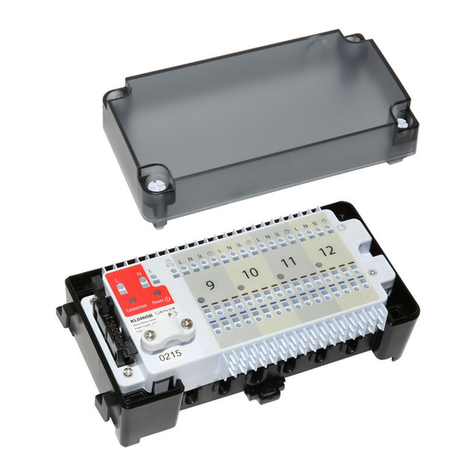
Triton Blue TR C 1224 User manual

Triton Blue
USER MANUAL
MANUAL DE USUARIO
CONTROLLER 12/24 TR C 1224
COTROLADOR 12/24 TR C 1224
Read kindly this user manual before using the machine
Lea atentamente este manual antes de utilizar el aparato
D
N
I
L
BE
M
O
HC
N
Y
S
P
A
TN
O
-
L
L
U
FT
U
O
K
C
A
L
B
0
1
8
6
4
2
0
0
1
8
6
4
2
0
0
1
8
6
4
2
0
0
1
8
6
4
2
0
0
1
8
6
4
2
0
0
1
8
6
4
2
0
0
1
8
6
4
2
0
0
1
8
6
4
2
0
0
1
8
6
4
2
0
0
1
8
6
4
2
0
0
1
8
6
4
2
0
0
1
8
6
4
2
0
0
1
8
6
4
2
0
0
1
8
6
4
2
0
0
1
8
6
4
2
0
0
1
8
6
4
2
0
0
1
8
6
4
2
0
0
1
8
6
4
2
0
0
1
8
6
4
2
0
0
1
8
6
4
2
0
0
1
8
6
4
2
0
0
1
8
6
4
2
0
0
1
8
6
4
2
0
0
1
8
6
4
2
00
1
8
6
4
2
0
1234567890
11
12
1
3
14
15
16
17
18
19
10
21
22
23
24
2
1234567890
11
12
1
S
E
N
E
C
S
P
E
T
S
C
E
R
N
W
O
D
V
E
R
T
A
E
BV
E
R
E
S
A
H
CE
N
O
V
E
R
E
T
E
L
E
DT
R
E
S
N
IT
I
D
E
G
O
F
E
N
I
H
C
A
M
V
E
R
L
L
A
D
R
O
C
E
R
T
F
I
H
S
P
E
T
SO
I
D
U
A
D
D
A
L
L
I
K
E
G
A
P
E
D
O
M
K
R
A
D
E
S
A
H
C
K
R
A
P
B
S
E
N
E
C
SE
S
A
H
C
X
I
M
E
S
A
H
C
E
L
G
N
I
S
D
L
O
H
R
E
T
S
A
M
AB
E
D
A
FD
E
E
P
SL
E
V
E
L
O
I
D
U
A
N
I
M
5N
I
M
0
1
A
E
L
B
U
O
D
4
2
-
1
E
L
G
N
IS
T
C
E
L
E
S
D
E
E
P
S
C
E
RC
E
R
R
A
E
L
C
C
E
R
T
I
X
E
P
U
R
E
M
M
I
D
E
M
I
T
D
E
E
P
S
E
M
I
T
E
D
A
F
1234
T
ESE
RP
T
E
S
E
RP
T
N
A
TS
N
IC
E
S
I
.C
E
S
I
.
S
N
I
ME
D
O
ME
D
O
M
S
N
I
MS
N
I
M
W
O
HS WO
HS
s
2
.
s
5
.
s
1
s
2
s
5
s
0
1
s
0
3
m
1
m
2
m
5
s
2
.s2
.
s
5
.
s
1
s1
s
2
s
2
s
5
s5
s
0
1
s0
1
s
03
s
0
2
m
1
m
1
m
2
m
2
m
5
m
5
m
0
1
m
01
0
1
8
6
4
2
0

English
Triton Blue
USER MANUAL
CONTROLLER TR C 1224
D
N
I
L
BE
M
O
HC
N
Y
S
P
A
TN
O
-
L
L
U
FT
U
O
K
C
A
L
B
0
1
8
6
4
2
0
0
1
8
6
4
2
0
0
1
8
6
4
2
0
0
1
8
6
4
2
0
0
1
8
6
4
2
0
0
1
8
6
4
2
0
0
1
8
6
4
2
0
0
1
8
6
4
2
0
0
1
8
6
4
2
0
0
1
8
6
4
2
0
0
1
8
6
4
2
0
0
1
8
6
4
2
0
0
1
8
6
4
2
0
0
1
8
6
4
2
0
0
1
8
6
4
2
0
0
1
8
6
4
2
0
0
1
8
6
4
2
0
0
1
8
6
4
2
0
0
1
8
6
4
2
0
0
1
8
6
4
2
0
0
1
8
6
4
2
0
0
1
8
6
4
2
0
0
1
8
6
4
2
0
0
1
8
6
4
2
00
1
8
6
4
2
0
1234567890
11
12
1
3
14
15
16
17
18
19
10
21
22
23
24
2
1234567890
11
12
1
S
E
N
E
C
S
P
E
T
S
C
E
R
N
W
O
D
V
E
R
T
A
E
BV
E
R
E
S
A
H
CE
N
O
V
E
R
E
T
E
L
E
DT
R
E
S
N
IT
I
D
E
G
O
F
E
N
I
H
C
A
M
V
E
R
L
L
A
D
R
O
C
E
R
T
F
I
H
S
P
E
T
SO
I
D
U
A
D
D
A
L
L
I
K
E
G
A
P
E
D
O
M
K
R
A
D
E
S
A
H
C
K
R
A
P
B
S
E
N
E
C
SE
S
A
H
C
X
I
M
E
S
A
H
C
E
L
G
N
I
S
D
L
O
H
R
E
T
S
A
M
AB
E
D
A
FD
E
E
P
SL
E
V
E
L
O
I
D
U
A
N
I
M
5N
I
M
0
1
A
E
L
B
U
O
D
4
2
-
1
E
L
G
N
IS
T
C
E
L
E
S
D
E
E
P
S
C
E
RC
E
R
R
A
E
L
C
C
E
R
T
I
X
E
P
U
R
E
M
M
I
D
E
M
I
T
D
E
E
P
S
E
M
I
T
E
D
A
F
1234
T
ESE
RP
T
E
S
E
RP
T
N
A
TS
N
IC
E
S
I
.C
E
S
I
.
S
N
I
ME
D
O
ME
D
O
M
S
N
I
MS
N
I
M
W
O
HS WO
HS
s
2
.
s
5
.
s
1
s
2
s
5
s
0
1
s
0
3
m
1
m
2
m
5
s
2
.s2
.
s
5
.
s
1
s1
s
2
s
2
s
5
s5
s
0
1
s0
1
s
03
s
0
2
m
1
m
1
m
2
m
2
m
5
m
5
m
0
1
m
01
0
1
8
6
4
2
0

TR-SRL-574 English
Pag. 3
I. PRODUCT DESCRIPTIONS
Thank you for using our company the TR-C-1224. To optimize the performance
of this product, please read these operating instructions carefully to familiarize
yourself with the basic operations of this unit. The TR-C-1224 is a unique 48 DMX
channel. This unit has been tested at the factory before being shipped to you,
there is no assembly required. It features include:
•Read the instruction in this manual carefully and throughly, as they give important
information regarding safety during use and maintenance. Please keep this
manual with the unit, in order to consult it in the future.
II.- WARNINGS
1. To prevent or reduce the risk of electrical shock or fire, do not expose this
unit to rain or moisture.
2. Clearing memory often may cause damage to the memory chip, be careful
not to initialize your unit frequency often to avoid this risk.
3. Only use the recommended AC/DC power adaptor.
4. Be sure to save the packing carton in case you may ever have to return the
unit for service.
5. Do not spill other liquids or water in to or on to your amplifier.
6. Be sure that the local power outlet match that or the required voltage for your
amplifier.
7. Do not attempt to operate this unit if the power cord has been frayed or
broken. Please route your power cord out of the way of foot traffic.
8. Do not attempt to remove or break off the ground prong from the electrical
cord. This prong is used to reduce the risk of electrical shock and fire in case
of an internal short.
9. Disconnect from main power before making any type of connection.
10. Do not remove the top cover under any conditions. There are no user
serviceable parts inside.
11. Disconnect the unit’s main power when left unused for long periods of time.
12. This unit is not intended for home use.
13. Carefully inspect this unit for damage that may have incurred during
shipping. If the unit appears to be damaged, do not attempt any operation,
please contact your dealer.
14. This unit should be operated by adults only, never allow small children
tamper or play with this unit.
15. Never operate this unit under the following conditions:
- In places subject to excessive humidity
- In places subject to excessive vibration or bumps
- In area with a temperature over 450C/1130 F or less than 20C/35.60 F
III. CAUTIONS
1. There are no user serviceable parts inside this unit.

English TR-SRL-574
Pag. 4
2. Do not attempt any repairs yourself, doing so will void your manufactures
warranty.
3. In the unlikely event your unit may require service please contact your
nearest dealer.
IV .- CONTROLS AND FUNCTIONS
Front Panel:
1. Preset A LEDs: Show the current intensity of the relevant channel numbered
from 1 to 24.
2. Channel Sliders 1-12: These 12 sliders are used to control and /or program
the intensities of channels 1-12.
3. Flash Buttons 1-24: These 12 buttons are used to bring an individual
channel, to full intensity.
4. Preset B LEDs: Show the current intensity of the relevant channel numbered
from 25-48.
5. Scene LEDs: Light when relevant scenes are active.
6. Channel Sliders 13-24: These 12 sliders are used to control and /or program
the intensities of channels 13-24.
7. Flash Buttons 13-24: These 12 buttons are used to bring an individual
channel, to full intensity. They also are used for programming.
8. Dark Button: This button is used to momentarily black out overall output.
9. Down/Beat Rev: Down functions to modify a scene in Edit mode, BEAT
REV is used to reverse the chasing direction of a program with regular beat.
10. Mode Select/Rec Speed: Each tap will activate the operating mode in the
order: .CHNS/SCENES, Double Preset and Single Preset. Rec Speed: Set the
speed of any of the programs chasing in Mix mode.
11. Up/Chase Rev: Up is used to modify a scene in Edit mode. Chase Rev is
to reverse the chasing direction of a scene under Speed Slider control.
12. Page Button: Tap to select pages of scenes from Page 1-4.
13. Delete/Rev One: Delete any step of a scene or reverse the chasing direction
of any program.
BLIND HOME TA P SYNC FULL-ON BLACK OUT
SCENES
DO WN DEL ETE INS E RT EDIT
SHIFT
STEP AUDI O
HO LD
MASTER FADE SPEED AUDIO LEVEL
5MIN 1 0MIN
REC SPEE D REC
CLE AR
REC
EXI T
UP
BEAT REV CHAS E REV RE V ONE ALL RE V% OR 0-255
REC ORD
ADD
KIL LPAGE
MO DE
DARK S ELEC T
1 2 3 4
MIX CH ASE
SING LE CHASE
CHASE
PARK
B
SCENE S
A
DOUBLE
1-48
SINGLE
PRESE T
PRESE T
10
8
6
4
2
010
8
6
4
2
0
A B
INSTANT
MINS
.2s
.5s
1s
2s
5s
10s
30s
1m
2m
5m
10m
10
8
6
1
8 9 10 11 12 13 14 15 34
16
18
23
33
32
24
2619 27 28 29 30
25 31
22
21
20
17
3
4
5
6
7
2
4
2
0
10
8
6
4
2
0
.ISEC .ISEC
MODE MODE
MINS MINS
SHOW SHOW
.2s .2s
.5s
1s
1s
2s
2s
5s
5s
10s
10s
30s
20s
1m
1m
2m
2m
5m
5m
10m
REC STE P
DIMM ER
SPE ED TI ME
FADE TIME
10
8
6
4
2
0
10
8
6
4
2
0
10
8
6
4
2
0
10
8
6
4
2
0
10
8
6
4
2
0
10
8
6
4
2
0
10
8
6
4
2
0
10
8
6
4
2
0
10
8
6
4
2
0
10
8
6
4
2
0
10
8
6
4
2
0
10
8
6
4
2
0
10
8
6
4
2
0
10
8
6
4
2
0
10
8
6
4
2
0
10
8
6
4
2
0
10
8
6
4
2
0
10
8
6
4
2
0
10
8
6
4
2
0
10
8
6
4
2
0
10
8
6
4
2
0
10
8
6
4
2
0
10
8
6
4
2
0
10
8
6
4
2
0
10
8
6
4
2
0
10
8
6
4
2
0
10
8
6
4
2
0
10
8
6
4
2
0
10
8
6
4
2
0
10
8
6
4
2
0
10
8
6
4
2
0
10
8
6
4
2
0
10
8
6
4
2
0
10
8
6
4
2
0
10
8
6
4
2
0
10
8
6
4
2
0
10
8
6
4
2
0
10
8
6
4
2
0
10
8
6
4
2
0
10
8
6
4
2
0
10
8
6
4
2
0
10
8
6
4
2
0
10
8
6
4
2
0
10
8
6
4
2
0
10
8
6
4
2
0
10
8
6
4
2
0
1 2 3 4 5 6 7 8 9 10 13 16 19 2211 14 17 20 2312 15 18 21 24
1 2 3 4 5 6 7 8 9 10 13 16 19 2211 14 17 2 0 2312 15 18 2 1 24
25 2 6 27 28 2 9 30 31 32 33 34 37 40 43 4635 38 41 44 4736 39 4 2 45 48
HEATI NG
READY
F OG
MACHINE
SCENE SETTER-48

TR-SRL-574 English
Pag. 5
14. Segment Display: Shows the current activity or programming state.
15. Insert / % or 0-255: Insert is to add one step or steps into a scene. % or
0-255 is used to change display value cycle between % and 0-255.
16. Edit/All Rev: Edit is used to activate Edit mode. All Rev is to reverse the
chasing direction of all programs.
17. Add or Kill/Rec Exit: In Add mode, multiple scenes or Flash buttons will be
on at a time. In Kill mode, pressing any Flash button will kill any other scenes
or programs. Rec Exit is used to exit from Program or Edit mode.
18. Record/Shift: Record is used to activate Record mode or program a step.
Shift functions only used with other buttons.
19. Master A Button: Brings channel 1-12 to full of current setting.
20. Park Button: Used to select Single/Mix Chase, bring Channel 13-24 to
full of current setting, or momentarily program a scene into Master B slider,
depending on the current mode.
21. Hold Button: This button is used to maintain current scene.
22. Step Button: This button is used to go to next step when the Speed Slider
is pushed to the bottom or in Edit mode.
23. Audio Button: Activates audio sync of chase and audio intensity effects.
24. Master Slider A: This slider controls overall output of all channels.
25. Master Slider B: This slider controls the chase of all channels.
26. Blind Button: This function takes the channel out of the chase of a program
in CHNS/SCENE mode.
27. Home Button: This button is used to deactivate the Blind.
28. Tap Sync Button: Repeatedly tapping this button establish the chase
speed.
29. Full On Button: This function bring overall output to full intensity.
30. Black Out Button: This button is used to kill all output with exception for that
resulting from Flash and Full On.
31. Fade Time Slider: Used to adjust the Fade Time.
32. Speed Slider: Used to adjust the chase speed.
33. Audio Level Slider: This slider controls the sensitivity of the Audio input.
34. Fog Machine Button.
Rear Panel:
3635 37 38 39 40 41 42
DC INPUT
AUDIODMX OUT REMOTE FOG MACHINEMIDI
1=Ground
2=Data+
3=Data-
1=Ground
2=Data-
3=Data+
THRU OUT IN
DC 12V 20V
500 mA min
LINE IN
DMX polarity select
1/4"stereo jack
Full on
Stand By
or Black Out GND
100mV 1Vp-p
2
3
1
ON OFF
35. Power Switch: This switch controls turning on or off the power.
36. DC Input: DC 12-20V, 500Ma Min.
37. MIDI Thru/Out/In: MIDI ports for connection to a sequencer or MIDI
device.
38. DMX Out: This connector sends your DMX value to the DMX fixture or

English TR-SRL-574
Pag. 6
DMX pack.
39. DMX Polarity Select: Used to select DMX polarity.
40. Audio Input: This jack accepts a line level audio input signal ranged from
100Mv to 1V pp.
41. Remote Input: Black Out and Full On may be controlled by a remote control
using a standard 1/4” stereo jack.
42. Fog Machine Connector.
V.- OPERATION
1. Being Programming
1.1 Recond Enable
1) Press and hold down the Record button.
2) While holding down the Record button, tap the Flash buttons 1, 6, 6 and 8 in
sequence.
3) Release the Record button, the Record LED lights up, now you can begin
programming your chase patterns.
NOTE:
The first time you turn on your unit, the default setting of the Record Code is Flash
buttons 1, 6, 6 and 8.
You may change the Record Code to protect your programms.
1.2 Security for Your Programs
To protect your programs from any editing by others, you may change the
Record Code.
1) Enter current Record Code (Flash buttons 1, 6, 6 and 8).
2) Press and hold down the Record and Edit buttons at a time.
3) While holding the Record and Edit buttons, tap the desired Flash button to
enter a new Record Code.
The Record Code consists of 4 Flash buttons(the same button or different
buttons), be sure your new Record Code consists of 4 Flash buttons.
4) Enter your new Record Code a second time, all channel LEDs and scene
LEDs will flash three time, now the Record Code is changed.
5) Exit Record mode. Tap the Rec Exit button while pressing and holding down
the Record button, release the two buttons at a time, the Record mode is
disengaged.
IMPORTANT!!!
Always remember to exit Record mode when you won’t continue your
programming, otherwise you may lose control of your unit.
NOTE:
The second time you enter your new Record Code different from that of the
first time, the LEDs will not flash, which means you’ve failed to change the

TR-SRL-574 English
Pag. 7
Record Code.
When you’ve entered a new Record Code the first time, and now you want to
cancel the new Record Code, you may press and hold down the Record and
Exit buttons at a time to exit.
1.3 Program Scenes
1) Record Enable.
2) Select the 1-24 Single mode by tapping the Mode Select button. This will give
you control of all 48 channels as you program.
Be sure that Master A & B are both set at maxium.(Master A is at its maximum
in the fully up position, while Master B is at its maximum in the fully down
position.)
3) Create a desired scene using Channel Sliders 1-24. At 0% or DMX 255, these
sliders should be at 10 position.
4) Once the scene is satisfactory, tap the Record button to program the scene as
step into the memory.
5) Repeat step 3 and 4 until all desired steps have been programmed into
memory. You may program up to 1000 steps into memory.
6) Select a chase bank or scene master to store your program. Tap the Page
button select a page (Page 1-4) to store your scenes.
7) Press a Flash button between 13-24 while holding down the Record button. All
LED will flash indicating the scenes have been programmed into memory.
8) You can continue programming or exit. To exit Program mode, tap the Exit
button while holding down the Record LED should go out.
EXAMPLE: Program a 16 steps chase with channel 1-19 at full in sequence I
nto Flashbutton 13 of Page 1.
1) Record enable.
2) Push Master A & B to maximum position and Fade silder to top.
3) Tap the Mode Select button to select 1-12 Signle mode.
4) Push Channel slider 1 to the top position, its LED light at full intensity.
5) Tap the Record button to program this step into memory.
6) Repeat steps 4 and 5 until you’ve programmed Channel sliders 1-19.
7) Tap the Page button causing Page 1 LED lights.
8) Tap the Page button 13 while holding down the Record button, all LEDs
will flash indicating you’ve programmed the chase into memory.
2. Editing
2.1 Edit Enable
1) Record enable.
2) Use the Page button to select the page the program you wish to edit is
on.
3) Tap the Mode Select button to select CHNS SCENES.

English TR-SRL-574
Pag. 8
4) Press and hold down the Edit button.
5) While holding down the Edit button, tap the Flash button that corresponds
to program you wish to edit.
6) Release the Edit button, the relevant scene LED should light indicating
you are in the Edit mode.
2.2 Erase a Program
1) Record enable.
2) Use the Page button to select the page the program you wish to erase is
on.
3) While holding down the Edit button, tap the Flash button (13-24) twice.
4) Release the two buttons, all LEDs flash, indicating the program is
erased.
2.2 Erase All Programs
1) Press and hold the Record button.
2) Tap the Flash buttons 1, 4, 2 and 3 in sequence while holding the Record
button. All LEDs will flash, indicating all programs stored in memory have
been erased.
2.4 Clear a Scene or Scenes
1) Record enable.
2) Record a scene or scenes.
3) If you not satisfied with the scene or scenes, you may tap the Rec Clear
button while pressing and holding the Record button, all LEDs will flash,
indicating the scenes have been cleared.
2.5 Delete a Step or Steps
1) Record enable.
2) Tap the Step button to scroll to the step you wish to delete.
3) Tap the Delete button when you reach to the step you wish to delete, all
LEDs will flash briefly indicating the deletion of the step.
4) Continue steps 2 and 3 until all the unwanted steps have been deleted.
5) Tap the Rec Exit button while pressing and holding down the Record
button, the Scene LED goes out, indicating the exit of Edit mode.
EXAMPLE: Delete the third step of the program on Flash button 25 on Page
2.
1) Record enable.
2) Tap the Mode Select button to select CHNS SCENE mode.
3) Tap the Page button until Page 2 LED lights.
4) Tap the Flash button 13 while pressing and down the Edit button, the
Scene LED lights.
5) Tap the Step button to scroll to the third step.
6) Tap the Delete button to delete the step.
7) Tap the Rec Exit button while pressing and holding down the Record
button to exit Edit mode.
2.6 Insert a Step or Steps
1) Record a scene or scenes you wish to insert.
2) Be sure you’re in and CHNS SCENE Enter the Edit mode.

TR-SRL-574 English
Pag. 9
3) Tap the Step button to scroll to the step which you wish to insert before.
You may read the step from the Segment Display.
4) Tap the Insert button to insert the step you’ve created before, all LEDs will
flash, indicating the step is inserted.
5) Exit Edit mode.
EXAMPLE: Insert a step with channels 1-12 fully on at a time between step 4
and 5 of program 35.
1) Record enable.
2) Push Channel sliders 1-12 to the top and record the scene as a step.
3) Tap the Mode Select button to select CHNS SCENE mode.
4) Tap the Page button until Page 2 LED lights.
5) Tap the Flash button 35 while holding down the Edit button, the
corresponding scene LED lights.
6) Tap the Step button to scroll to the step 4.
7) Tap the Insert button to insert the scene you’ve created before.
2.7 Modify a Step or Steps
1) Enter Edit mode.
2) Tap the Step button to scroll to the step you wish to modify.
3) Press and hold the Up button if you want to raise the intensity. If you want
to lower the intensity, press and hold down the Down button.
4) While holding down the Up or Down button, tap the Flash button
corresponding to the DMX channel of the scene you wish to modify until
you reach the desired intensity value read from the Segment Display.
Then you may tap the Flash buttons until you are satisfied with the new
scene.
5) Repeat steps 2, 3 and 4 until all the steps have been modified.
6) Exit Edit mode.
3. Running
3.1 Running Chase Programs
1) Tap the Mode Select button to select CHNS SCENES mode indicated
by the red LED.
2) Tap the Page button to select the correct page the program you wish to
run is located.
3) Push Master Slider B to its maximum position(fully down).
4) Move the desired Channel slider (13-24) to its maximum positio to trigger
the program, and the program will fade in depending upon current fade
time.
5) Move the Channel slider to adjust the output of the current program.
3.2 Running a Program To Audio
1) Use built-in microphone or plug the audio source into the RCA Audio
jack.
2) Select your program as described above.
3) Tap the Audio button until its LED lights, indicating Audio mode is active.
4) Use the Audio level slider to adjust the music sensitivity.

English TR-SRL-574
Pag. 10
5) To return to normal mode, tap the Audio button a second time causing its
LED goes out, the Audio mode is disengaged.
3.3 Running a Programs With the Speed Slider
1) Be sure the Audio mode is disengaged, that is the Audio LED goes out.
2) Select your program as described above.
3) Move the Speed slider to the SHOW MODE position (the botton), then tap
the Flash button (13-24) while pesssing and holding down the Rec Speed
button, the corresponding program will not run with the Standard beat any
longer.
4) Now you may move the Speed Slider to select your desired speed.
NOTE: The step 3 is not necessary if the selected program is not recorded with
Standard Beat.
3.4 Running a Programs With the Standard Beat
1) Be sure the Audio mode is disengaged. Tap the Mode Select button to
select CHNS SCENE mode.
2) Tap the Park button to select Mix Chase mode, the LED lights indicating
this selection.
3) Select your program as described above.
4) Move the Speed slider until Segment Display reads your desired value.
You may tap the Tap Sync button twice to define your beat time.
5) While pressing and holding down the Rec Speed button, tap the Flash
button(25-48) that stores the program.
6) The program will then run with the set time or beat when engaged.
7) Repeat steps 4 and 5 to set a new beat time.
4. Chang the Speed Mode between 5 Minutes and 10 Minutes
1) Press and hold the Record button.
2) Tap the Flash button 5 or 10 three times while holding down the Record
button.
3) The 5 MIN or 10 MIN should light up indicating the Speed slider is set to
run in the 5 or 10 minute mode..
5. MIDI
5.1 Setting MIDI IN
1) Tap the Flash button 1 three times while holding down the Record button,
the Segment Display reads “CHI” indicating MIDI IN channel setup is
available.
2) Tap the Flash button numbered from 1-16 to assign MIDI IN Channel 1-
16, the relevant channel LED lights indicating MIDI IN channel is set.
5.2 Setting MIDI OUT
1) Tap the Flash button 2 three times while holding down the Record button,
the Segment Display reads “CHO” indicating MIDI IN channel setup is
available.
2) Tap the Flash button numbered from 1-16 to assign MIDI OUT Channel 1-

TR-SRL-574 English
Pag. 11
16, the relevant channel LED lights indicating MIDI OUT channel is set.
5.3 Exit MIDI Setting
Press and hold down the Record button. While holding down the Record button
tap the Rec Exit button to exit MIDI setting.
5.4 Receiving MIDI File Dump
Tap the Flash button 3 three time while holding down the Record button, the
Segment Display reads “IN” indicating the controller is ready to receive MIDI
file dump.
5.5 Sending MIDI File Dump
Tap the Flash button 4 three time while holding down the Record button, the
Segment Display reads “OUT” indicating the controller is ready to send a file.
NOTE:
1) During file dump, all other operations will not function. Functions will
automatically return when the file dump is completed.
2) File dump will be interrupted and stop if errors occur or power failure.
5.6 Implementation
1) During receiving and sending MIDI data, all MIDI scenes and channels
being run will automatically paused if there is no response within 10
minutes.
2) During receiving and sending file dump, the controller will automatically
search for or send Device ID of 55h(85), a file named DC2448 with an
extension of “BIN(SPACE)”.
3) File dump allows this controller to send its MIDI data to next unit or other
MIDI devices.
4) Threr are two types of file dump mode described as below:
CONTROLLER
CONTROLLER
Open Loop Mode
Close Loop Mode
RECEIVER
RECEIVER
MIDI OUT
MIDI OUT
MIDI OUT
MIDI OUT
MIDI IN
MIDI IN
MIDI IN
MIDI IN
5) The controller will send and receive Note On Off data via the Flash
buttons.
NOTE NUMBER VELOCITY FUNCTION
Decimal Hex
22-69 [16H-45H] Program master Turn on or off
program 1-24

English TR-SRL-574
Pag. 12
22-117 [16H-45H] channel light activate Channel
1-48
118 [76H] FULL-ON
119 [77H] DARK
120 [78H] HOLD
121 [79H] Turn on or off
AUDIO
122 [7AH] CHNS
SCENES
123 [7BH] DOUBLE
PRESET Mode
124 [7CH] SINGLE PRESET
Mode
125 [7DH] Step
126 [7EH] BLACK OUT
VI.- BRIEF OF MAIN FUNCTIONS
1. Reverse the direction of the scene
1) Reverse the direction of all the scenes. Press the ALL REV Button, all the
scenes should change their directions.
2) Reverse the chaseing direction of all the programs with speed control:
Press the Chase Rev Button.
3) Reverse the chaseing direction of all the programs with standard beat:
Press the Beat Rev Button.
4) Reverse chaseing direction of any program: Press and hold down the
Rec One Button, then press down the Flash Button corresponding to your
desired program and release together.
2. Fade Time
1) The amount of time it will take for the dimmer to go from zero output to
maximum output, and vice verse.
2) Fade time is adjusted through the Fade Time Slider, which varies from
instant to 10 mimutes.
3. Tap Sync Button
1) The Tap Sync button is used to set and synchronize the chase rate (the
rate at which all scenes will sequence) by tapping the button several
times. The chase rate will synchronize to the time of the last two taps. The
LED above the Step Button will flash at the new chase rate. The chase
rate may be set anytime whether or not a program is running.
2) Tap Sync will override any previous setting of the speed slider control until
the slider is moved again.
3) Use of Tap Sync in setting a standard beat is the same with speed control

TR-SRL-574 English
Pag. 13
slider.
4. Master Slider
Master Slider control provides proportion level control over all channels and
scenes with the exception of the Flash Buttons. For example:
Whenever the Master slider control is at minimum all stage outputs will be at zero
except for any resulting from a Flash Button or FULL ON Button.
If the Master is at 50%, all outputs will be at only 50% of the setting of current
channel or scenes except for any resulting from a Flash Button or FULL ON
Button.
If the Master is at full all outputs will follow the unit setting.
Master A always controls outputs of channels. Master B controls program or a
scene except in Double Press Mode.
5. Single Mode
1) All programs will run in sequential order starting in the order of program
number.
2) The Segment Display will read the running program number.
3) All programs will be controlled by the same Speed Slider.
4) Press the MODE SELECT BUTTON and select “CHNS SCENES”.
5) Press the PARK BUTTON to select SINGLE CHASE MODE. A red LED
will indicate this selection.
6. Mix Mode
1) Will run all programs synchronously.
2) All programs can be controlled by the same SLIDER SPEED, or each
programs speed may be controlled individually. (See Speed Setting).
3) Press the MODE SELECT BUTTON and select “CHNS SCENES”.
4) Press the PARK BUTTON to select MIX CHASE MODE. A yellow LED will
indicate this selection.
7. Dimmer Display
1) The 3-Digit Seqment Display is used to display intensity percentage or
absolute DMX value.
2) To change between percentage and absolute value: Press and hold the
Shift Button. While holding down the Shift button press the 5 or 0-255
Button to switch between percentage and absolute values.
3) If the Segment Display reads, for example, “076”, it means a percentage
value 76%. If the Segment Display reads “076”, it means the DMX value
76.
8. Blind and Home
1) Blind function takes channels temporally out from a chase, when the
chase is running, and gives you manual control over the channel.
2) Press and hold the Blind Button and tap the relative Flash Button you
want to temporarily take out of the chase.
3) To return to normal chase again press and hold the Home Button and
push the Flash Button you want to return to normal chase.

English TR-SRL-574
Pag. 14
VII.- TECHNICAL SPECIFICATIONS
Power Input DC 12~18V 500mA Min.
DMX Out 3 pin male XLR socket x 1
MIDI In/Out/Thru 5 pin multiple socket
Dimensions 710x266x90mm
Weight 6.3 Kgs

Español
Triton Blue
MANUAL DE USUARIO
CONTROLADOR TR C 1224
D
N
I
L
BE
M
O
HC
N
Y
S
P
A
TN
O
-
L
L
U
FT
U
O
K
C
A
L
B
0
1
8
6
4
2
0
0
1
8
6
4
2
0
0
1
8
6
4
2
0
0
1
8
6
4
2
0
0
1
8
6
4
2
0
0
1
8
6
4
2
0
0
1
8
6
4
2
0
0
1
8
6
4
2
0
0
1
8
6
4
2
0
0
1
8
6
4
2
0
0
1
8
6
4
2
0
0
1
8
6
4
2
0
0
1
8
6
4
2
0
0
1
8
6
4
2
0
0
1
8
6
4
2
0
0
1
8
6
4
2
0
0
1
8
6
4
2
0
0
1
8
6
4
2
0
0
1
8
6
4
2
0
0
1
8
6
4
2
0
0
1
8
6
4
2
0
0
1
8
6
4
2
0
0
1
8
6
4
2
0
0
1
8
6
4
2
00
1
8
6
4
2
0
1234567890
11
12
1
3
14
15
16
17
18
19
10
21
22
23
24
2
1234567890
11
12
1
S
E
N
E
C
S
P
E
T
S
C
E
R
N
W
O
D
V
E
R
T
A
E
BV
E
R
E
S
A
H
CE
N
O
V
E
R
E
T
E
L
E
DT
R
E
S
N
IT
I
D
E
G
O
F
E
N
I
H
C
A
M
V
E
R
L
L
A
D
R
O
C
E
R
T
F
I
H
S
P
E
T
SO
I
D
U
A
D
D
A
L
L
I
K
E
G
A
P
E
D
O
M
K
R
A
D
E
S
A
H
C
K
R
A
P
B
S
E
N
E
C
SE
S
A
H
C
X
I
M
E
S
A
H
C
E
L
G
N
I
S
D
L
O
H
R
E
T
S
A
M
AB
E
D
A
FD
E
E
P
SL
E
V
E
L
O
I
D
U
A
N
I
M
5N
I
M
0
1
A
E
L
B
U
O
D
4
2
-
1
E
L
G
N
IS
T
C
E
L
E
S
D
E
E
P
S
C
E
RC
E
R
R
A
E
L
C
C
E
R
T
I
X
E
P
U
R
E
M
M
I
D
E
M
I
T
D
E
E
P
S
E
M
I
T
E
D
A
F
1234
T
ESE
RP
T
E
S
E
RP
T
N
A
TS
N
IC
E
S
I
.C
E
S
I
.
S
N
I
ME
D
O
ME
D
O
M
S
N
I
MS
N
I
M
W
O
HS WO
HS
s
2
.
s
5
.
s
1
s
2
s
5
s
0
1
s
0
3
m
1
m
2
m
5
s
2
.s2
.
s
5
.
s
1
s1
s
2
s
2
s
5
s5
s
0
1
s0
1
s
03
s
0
2
m
1
m
1
m
2
m
2
m
5
m
5
m
0
1
m
01
0
1
8
6
4
2
0

Español TR-C-2448
Pag. 16
I.- Descripción:
Para optimizar el funcionamiento de este producto, por favor lea atentamente estas
instrucciones para familiarizarse con el funcionamiento básico de este aparato. El
TR-C-1224 es un controlador de 24 canales de DMX. Esta unidad ha sido verificada
en la fábrica antes de proceder a su venta, este aparato no incluye ningún montaje
especial. Características principales:
Control de 48 canales de DMX
Programaciones de 96 chases
2 crossfaders independientes
Pantalla digital LCD de 3 dígitos
Memoria de seguridad ante un apagón.
Entradas estándar de MIDI y DMX
Varios modos de ejecución
Lea atentamente este manual, en el hay información importante sobre la seguridad
y mantenimiento del producto. Por favor mantenga esta manual al lado siempre del
aparato para futuras consultas.
II.- Advertencias
1. Para prevenir o reducir los riesgos de descargas eléctricas o incendio, no
exponga este aparato a la lluvia ni a la humedad.
2. No borre la memoria excesivamente, esto puede provocar fallo en el chip de
la memoria.
3. Solo use el adaptador de corriente recomendado.
4. Se recomienda mantener el embalaje original.
5. No vierta agua ni ningún otro líquido sobre el aparato.
6. Asegúrese de que el enchufe donde se va ha conectar el adaptador de
corriente cumple con las características requeridas.
7. No conecte el aparato si detecta que el cable del alimentador esta
deteriorado. No conecte el adaptador de corriente al alcance el público.
8. Asegúrese de que la conexión eléctrica tiene conexión a tierra. Esta
conexión esta para reducir el riesgo de descargas eléctricas.
9. Desconecte el aparato antes de realizar cualquier otra conexión.
10. No quite la cubierta principal bajo ninguna condición. En el interior del
producto no se encuentra ninguna pieza que necesaria para el usuario.
11. Desconecte el aparato si va ha estar un largo periodo sin usarse.
12. Este aparato no esta diseñado para uso domestico.
13. Examine cuidadosamente el aparto antes de desembalarlo para comprobar
de que no ha sufrido ningún desperfecto en el transporte, si este ha sufrido
algún desperfecto póngase en contacto con su vendedor.
14. Este aparato esta diseñado para su manejo por una persona adulta,
manténgalo fuera del alcance de los niños.
15. No opere este aparato bajo las siguientes condiciones:
a. En lugares con excesiva humedad

TR-C-2448 Español
Pag. 17
b. En lugares con excesivas vibraciones o en lugares donde pueda
recibir golpes.
c. En lugares con temperaturas que excedan de los 45ª C/113ª F o
menos de 2º C / 35.6º F
III.- Precauciones
1. En el interior del aparato no hay ninguna pieza necesaria para el usuario.
2. No intente reparar el aparato usted mismo, póngase en contacto con su
proveedor.
IV.- Controles y funciones.
Panel frontal:
1. LEDs preset A: Muestra la actual intensidad para los canales del 1 al 12
2. Potenciómetros canales 1 al 12: Estos 12 potenciómetros son usados para
control y/o programas la intensidad de los canales.
3. Botones flash canales 1 al 12: estos botones son usados como lanzar un
canal individualmente a la máxima intensidad.
4. LEDs preset B: Muestra la actual intensidad para los canales del 13 al 24.
5. LEDs de escenas: Se encienden cuando la escena a la que hace relación
es llamada.
6. Potenciómetros del 13 al 24: Estos 12 potenciómetros son usados para
control y/o programas la intensidad de los canales.
7. Botones flash canales 13 al 24: estos botones son usados como lanzar un
canal individualmente a la máxima intensidad.
8. Botón de oscura (Black-Out): Este botón es usado para hacer un oscuro
temporal en la salida de DMX.
9. Down / BEAT REV: La función “abajo” se usa para cambiar una escena
cuando se esta en modo EDIT. La función “BEAT REV” es usada para
cambiar el sentido de un chases.
D
N
I
L
BE
M
O
HC
N
Y
S
P
A
TN
O
-
L
L
U
FT
U
O
K
C
A
L
B
0
1
8
6
4
2
0
0
1
8
6
4
2
0
0
1
8
6
4
2
0
0
1
8
6
4
2
0
0
1
8
6
4
2
0
0
1
8
6
4
2
0
0
1
8
6
4
2
0
0
1
8
6
4
2
0
0
1
8
6
4
2
0
0
1
8
6
4
2
0
0
1
8
6
4
2
0
0
1
8
6
4
2
0
0
1
8
6
4
2
0
0
1
8
6
4
2
0
0
1
8
6
4
2
0
0
1
8
6
4
2
0
0
1
8
6
4
2
0
0
1
8
6
4
2
0
0
1
8
6
4
2
0
0
1
8
6
4
2
0
0
1
8
6
4
2
0
0
1
8
6
4
2
0
0
1
8
6
4
2
0
0
1
8
6
4
2
00
1
8
6
4
2
0
1234567890
11
12
1
3
14
15
16
17
18
19
10
21
22
23
24
2
1234567890
11
12
1
S
E
N
E
C
S
P
E
T
S
C
E
R
N
W
O
D
V
E
R
T
A
E
BV
E
R
E
S
A
H
CE
N
O
V
E
R
E
T
E
L
E
DT
R
E
S
N
IT
I
D
E
G
O
F
E
N
I
H
C
A
M
V
E
R
L
L
A
D
R
O
C
E
R
T
F
I
H
S
P
E
T
SO
I
D
U
A
D
D
A
L
L
I
K
E
G
A
P
E
D
O
M
K
R
A
D
E
S
A
H
C
K
R
A
P
B
S
E
N
E
C
SE
S
A
H
C
X
I
M
E
S
A
H
C
E
L
G
N
I
S
D
L
O
H
R
E
T
S
A
M
AB
E
D
A
FD
E
E
P
SL
E
V
E
L
O
I
D
U
A
N
I
M
5N
I
M
0
1
A
E
L
B
U
O
D
4
2
-
1
E
L
G
N
I
S
T
C
E
L
E
S
D
E
E
P
S
C
E
RC
E
R
R
A
E
L
C
C
E
R
T
I
X
E
P
U
R
E
M
M
I
D
E
M
I
T
D
E
E
P
S
E
M
I
T
E
D
A
F
1234
T
E
S
E
R
P
T
E
S
E
R
P
T
N
A
T
S
N
IC
E
S
I
.C
E
S
I
.
S
N
I
ME
D
O
ME
D
O
M
S
N
I
MS
N
I
M
W
O
H
SW
O
H
S
s
2
.
s
5
.
s
1
s
2
s
5
s
0
1
s
0
3
m
1
m
2
m
5
s
2
.s
2
.
s
5
.
s
1
s
1
s
2
s
2
s
5
s
5
s
0
1
s
0
1
s
0
3
s
0
2
m
1
m
1
m
2
m
2
m
5
m
5
m
0
1
m
0
1
0
1
8
6
4
2
0
1
2
3
4
5
6
7
891
12
13
14
15
16
17
1
8
1
9
1
1
2
2
2
3
24
2
5
2
6
2
7
2
8
2
9
2
1
3
2
33
34
3
0
1
0
2
0
3

Español TR-C-2448
Pag. 18
10. Mode Select/ Rec Speed: Cada pulsación del botón activara un modo de
operación en el siguiente orden: CHNS/SCENES, Double Preset y Single
Preset. El Rec Speed fija la velocidad de cualquier programa en modo Mix
Mode.
11. Up / Chase Rev: Up es usado para modificar una escena en modo “Edit”.
“Chase Rev” cambia la dirección de una escena mediante el control de
velocidad “Speed”.
12. Botón “Page”: Botón para seleccionar la pagina de escena deseada.
13. Delete / Rev One: Borra cualquier paso de una escena, o cambia a dirección
de cualquier programa.
14. Pantalla de control: Muestra la acción actual o el estado de la
programación.
15. Insert / % o 0~255: Insert un nuevo paso en una escena. “% or 0~255” es
usado para cambiar la escala de los valores mostrador en la pantalla de
control.
16. Edit / All Rev: Edit es usado para activar el modo de edición. All Rev cambia
la dirección de todos los programas.
17. Add or Hill / Rec Exit: En modo Add, varias escenas o botón de Flash pueden
ser activadas al mismo tiempo. En Hill Mode, pulsado el botón de Flash
mata cualquiera de las otras escenas o programas. El Rec Exit es usado
para salir de los modos de Program o Edit.
18. Record / Shift: Record es usado para activar el modo de grabación o para
programar un paso. La función Shift solo en usa en conjunción con otro
botón.
19. Botón Master A: Lanza los canales de 1 al 12 al nivel al que se hallan
programados.
20. Botón Park: Usado para seccionar Single / Mix Chase. Lanza los canales
del 13 al 24 al nivel al que se hallan programados, o temporalmente
programa una escena en los potenciómetros del Master B, dependiendo
del modo actual.
21. Botón Hold: Este botón es usado para mantener la escena actual.
22. Botón de Step: Este botón es usado para ir a la siguiente escena cuando
el botón de Speed Slide esta pulsado o en modo de edición.
23. Botón de Audio: Activa la sincronización por audio de un chases y la
intensidad de los efectos de audio.
24. Potenciómetro Master A: Este potenciómetro controla la salida total de los
canales.
25. Potenciómetro Master B: Este potenciómetro controla todos los chases de
todos lo canales.
26. Botón Blind: esta función toma la salida de los canales de un programa en
modo CHASE/ESCENA.
27. Botón Home: Este botón es usado para desactivar el “Blind”.
28. Botón Tap Sync: Golpear suavemente repetidamente para establecer la
velocidad del chases.
29. Botón Full On: Este botón pone todas las salidas a intensidad completa.

TR-C-2448 Español
Pag. 19
30. Botón Back-Out: Este botón es usado para apagar todas las salidas con
excepción de los que este activado mediante el botón flash y el Full On.
31. Potenciómetro Fade Time: Potenciómetro usado para ajustar el tiempo de
mezcla.
32. Potenciómetro de Speed: Potenciómetro usado para ajustar la velocidad
de los chases.
33. Potenciómetro de nivel de audio: Este controlador ajusta la sensibilidad de
la entrada de audio.
34. Botón Fog Machine.
35. Power Switch: Botón de encendido.
36. DC Input: Entrada del adaptador de corriente (DC 12 ~ 20V, 500mA
mínimo).
37. MIDI Thru/Out/In: Conectores para un secuenciador o un dispositivo MIDI.
38. DMX Out: Conector para salida de DMX a los dispositivos de control
DMX.
39. DMX Polarity select: Selector para la polaridad de la señal de DMX.
40. Audio Input: Conector tipo jack para la entrada de señal de audio, acepta
nivel de entrada de audio de 100mV a 1V.
41. Remote Input: Las funciones de Black Out y Full On pueden ser controladas
por un controlador remoto usando un conector jack stereo de 1/4”.
42. Conector Fog Machine: Conector para conectar la maquina de humo.
V.- Manejo.
1. Programación:
a. Activar grabación:
i. Pulse y mantenga el botón de Record.
ii. Mientras tiene pulsado el botón de grabación “Record”,
pulse los botones 1, 6, 6 y 8 en secuencia.
iii. Suelte el botón de grabación (Record), la luz
encima del botón de Record de se encenderá, ahora
usted puede empezar a programas los chases.
Nota:
La primera vez que se usa el aparato, el código por defecto
para activar el modo de grabación son lo botones de flash 1, 6, 6 y
8
Usted puede cambiar este código para proteger sus
5
36
37
38
39
31
42
43
4
0
4

Español TR-C-2448
Pag. 20
programas.
b. Seguridad de sus programas: para proteger sus programas de
cualquier cambio por parte de otro usuario, usted puede cambiar
el código de grabación (Record Code).
i. Introduzca el código de grabación por defecto (Botones
flash 1, 6, 6 y 8).
ii. Pulse y mantenga el botón de Record y Edit al mismo
tiempo.
iii. Mientras mantiene los dos botones pulsados, con
la ayuda de los botones de flash, introduzca el nuevo
código, este desde estar compuesto de 4 dígitos.
iv. Introducía el nuevo código de nuevo, después de
esto si el código introducido es el correcto, todos los leds
de flash y escenas se pondrán a parpadear tres veces
todas a la vez.
v. Salir del modo de grabación, pulse el botón de Rec
Exit mientras presiona y mantiene el botón de Record,
mantenga pulsado los dos botones durante un tiempo, en
modo de grabación se desactivara.
IMPORTANTE:
Recuerde salir antes del modo de grabación, el no salir
de este modo puede producir la perdida del control de la
unidad.
NOTA:
Si la segunda vez que se introduce el nuevo código es
diferente del de la primera vez, los leds no se encenderán, y
el cambio de código no se realizara.
Cuando se ha introducido un código de grabación por
primera, y se quiere cancelar la operación, pulse y mantenga
los botones de Record y Exit al mismo tiempo para salir.
c. Programación de una escena:
i. Activar el modo grabación.
ii. Seleccione modo simple de 1~24, pulsado el botón de
Select Mode. Esto permitirá controlar todos los canales
del 1 al 24. Asegúrese de que los niveles de salida están
a Full (Para cerciorarse de que esto es así compruebe
de que el Master A esta completamente hacia arriba el
Master B esta completamente hacia abajo).
iii. Crea una escena usando los potenciómetros de los
canales del 1~24. Usando valores en porcentaje o en
valores de DMX 255.
Table of contents
Languages:
Other Triton Blue Controllers manuals
