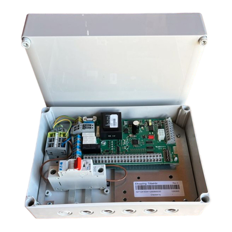
Nibe EBV 200 User manual

R
EBV 200
MAV 0517-5 411281
EBV 200
25A
25
25
2
4
6
8
10A
Till
Begränsning
StrömMarginal
Effektvakt 100
5V
LEK
LEK
LEK
DE
GB
SE MONTERINGSANVISNING BELASTNINGSVAKT EBV 200
INSTALLATION INSTRUCTIONS LOAD MONITOR EBV 200
MONTAGEANWEISUNG ÜBERLASTUNGSSCHUTZ EBV 200


Elanslutning
EBV 200
SE 1
När många elförbrukare är inkopplade i fastigheten
samtidigt som elkassetten är i drift, finns det risk att
fastighetens huvudsäkringar löser ut.
Om fasströmmen blir för hög, så minskar effektvakten
elkassettens effekt tills det sammanlagda ”strömut-
taget” understiger huvudsäkringens märkström.
När övrig strömförbrukning minskar tillräckligt mycket
kopplas elkassetten in igen med tillåten effekt.
Grön lysdiod lyser när strömmen är mindre än huvud-
säkringens märkström, ingen begränsning.
Röd lysdiod lyser när strömmen är större än huvud-
säkringens märkström, last kopplas bort med en steg-
tid på 10 s.
Röd lysdiod blinkar när strömmen har sjunkit under
huvudsäkringens märkström. Last fortsätter att vara
bortkopplad i 10 min.
Ratten ”Ström” ställs in på huvudsäkringens värde.
När strömuttaget överskrider detta värde börjar effekt-
vakten stega ner effekten på elkassetten.
Med ratten ”Marginal” ställs differensen in mellan
huvudsäkringens märkström och strömmen då effek-
ten är tillåten att åter kopplas in.
För 6 kW elpatron ställs ”Marginal” in på 5 A.
För 9 kW ställs ”Marginal” in på 4,5 A.
Värdet skall alltid ställas på den ström som den störs-
ta bortkopplade lasten skulle kunna dra.
4 kW elkoppling:
Tryck fast ”Effektvakt 100” på förberedd plats i elkopp-
lingsutrymmet strax ovanför plint för inkommande
elmatning. De bipackade korta kablarna ska använ-
das för inkopplingen till reläkortet.
5-10 kW elkoppling:
Bifogad plåt fästes med popnit på vänster sida av vär-
mepumpen. Belastningsvaktmodulen ”Effektvakt 100”
trycks fast på plåten. De bipackade långa kablarna
ska användas för inkopplingen till reläkortet.
Gemensamt:
Den 3-poliga kantkontakten anslutes till reläkortets
(29) kantkontakt position 8-10.
Den blå ledaren i 2-ledarkabeln anslutes till reläkortets
(29) plint (30) position 1.
Den bruna ledaren i 2-ledarkabeln anslutes till reläkor-
tets (29) plint (30) position 2.
Se ”Inkoppling och placering i FIGHTER 1210/1215”.
Belastningsvaktmodulen ”Effektvakt 100” trycks fast
på förberedd plats i elkopplingsutrymmet.
De bipackade korta kablarna ska användas för
inkopplingen till reläkortet.
Den 3-poliga kantkontakten klipps av. Kablarna anslu-
tes till plint (13) pos 3, 4.
Den blå ledaren i 2-ledarkabeln anslutes till reläkortets
(29) skruvplint (30) position 1.
Den bruna ledaren i 2-ledarkabeln anslutes till reläkor-
tets (29) skruvplint (30) position 2.
Se ”Inkoppling och placering i FIGHTER 1110/1115”.
25A
25
25
2
4
6
8
10A
Till
Begränsning
StrömMarginal
Effektvakt 100
5V
För att mäta strömmen ska en strömtransformator
monteras på vardera till elcentralen inkommande fas-
ledare. Denna montering sker lämpligen i elcentralen.
Anslut strömtransformatorerna till en mångledare i en
kapsling i direkt anslutning till elcentralen. Använd en
oskärmad mångledare med minst Ø 0,50 mm2från
kapslingen till värmepumpen.
De tre strömtransformatorernas ena ledare kopplas
samman och anslutes till terminal 1 på ”Effektvakt
100”. Den andra ledaren från respektive strömtrans-
formator anslutes till terminalerna märkta 2, 3 och 4.
LEK
LEK
LEK
Tekniska data
Ströminställning 16 - 35 A
Matningsspänning 230 V/50 Hz
Strömmarginal 2 - 10 A
LPEN 1L2L3
Elcentral
Till värmepump
Inkommande el
Strömtransformatorer
Funktion
Inställning av begränsning
Inkoppling, FIGHTER 1210/1215
Inkoppling, FIGHTER 1110/1115
EBV 200 är en belastningsvakt för bortkoppling av
effekt, överstigande den på belastningsvakten inställ-
da effekten. EBV 200 består av modulen ”Effektvakt
100”, fästplåt, kabelsats och tre strömtransformatorer.
Allmänt

EBV 200
SE2
LEK
+2
-2
1
R
0
Reläkort FIGHTER 1210/1215
30.1 30.2
29.8 29.10
Effektvakt 100
1234 67
8
10 12 13 14
Strömtransformatorer
Effektvakt 100
29 30
Inkoppling och placering i FIGHTER 1110/1115
Inkoppling och placering i FIGHTER 1210/1215
13
P
56789103412
LN
Reläkort FIGHTER 1110/1115
30.1 30.2
Effektvakt 100
1234 67
8
10 12 13 14
Strömtransformatorer
OBS!
Elinstallationen av detta tillbehör
skall utföras av behörig elinstallatör.
Elektrisk installation och lednings-
dragning skall utföras enligt
gällande bestämmelser.
13
29
29
Effektvakt 100
VB-Fram
49 (50) °C
Varmvatten
51 °C
LEK
Effektvakt 100
3029
3029
4kW 5 – 10 kW
Effektvakt 100
Bilden visar FIGHTER 1115 4kW med tillbehör.

Elanslutning
EBV 200
GB 3
When many power consumers are connected in the
property at the same time as the immersion heater is
operating, there is a risk of the property's main fuse
tripping.
If the phase current becomes so high, the load moni-
tor reduces the output of the immersion heater until
there is no longer a risk of the main fuses tripping.
When the general power consumption drops suffi-
ciently, the immersion heater is connected again.
A fixed green light indicates that the output is less
than the main fuse’s nominal current, which means no
limitation.
A fixed red light indicates that the output is stepped
down by approximately 10 s step time.
During the period the red LED flashes the output has
dropped below the main fuse’s nominal current. The
cutout of supply will continue for 10 minutes.
The current control “Ström” is set to the value of the
main fuse. When the current output exceeds this val-
ue, the load monitor starts to step down the output of
the immersion heater.
With the current control “Marginal” the difference is
chosen between the main fuse’s nominal current and
that current which allows the power to be cut in again.
For the 6 kW immersion heater, Marginal is set to 5 A.
For 9 kW, Marginal is set to 4.5 A. The value should
always be set to the current that the greatest discon-
nected load could draw.
25A
25
25
2
4
6
8
10A
Till
Begränsning
StrömMarginal
Effektvakt 100
5V
LEK
LEK
LEK
Technical specifications
Current setting 16 - 35 A
Supply voltage 230 V/50 Hz
Current margin 2 - 10 A
EBV 200 is a load monitor used to disconnect output
that exceeds the output set on the load monitor. EBV
200 consists of the Load Monitor 100 module, plate,
cable set and three current transformers.
General
Function
Setting the limitation

EBV 200
GB4
4 kW electrical connection:
Insert Load Monitor 100 into the prepared space in the
electrical connection area, just above the terminal
block for the incoming mains supply. The enclosed
short cables are used for connection to the relay card.
5-10 kW electrical connection:
The enclosed plate is secured using pop rivets on the
left-hand side of the heat pump. The load monitor
module, Load Monitor 100 is secured on the plate. The
enclosed long cables are used for connection to the
relay card.
Common:
The 3-way edge board connector is connected to the
relay card's (29) edge board connector positions 8-10.
The blue conductor of the 2-wire cable is connected to
the relay card's (29) terminal block (30) terminal posi-
tion 1.
The brown conductor of the 2-wire cable is connected
to the relay card's (29) terminal block (30) terminal
position 2.
See “Connecting and placement in FIGHTER
1210/1215”.
The load monitor module, Load Monitor 100 is pushed
into position in the prepared space in the electrical
connection area.
The enclosed short cables are used for connection to
the relay card.
The 3-way edge board connector is cut off. The cables
are connected to terminal block (13) positions 3 and 4.
The blue conductor of the 2-wire cable is connected to
the relay card's (29) screw terminal (30) position 1.
The brown conductor of the 2-wire cable is connected
to the relay card's (29) screw terminal (30) position 2.
See “Connecting and placement in FIGHTER
1110/1115”.
One current transformer should be installed on each
incoming phase conductor in to the distribution box to
measure the current. The ideal installation area is in
the distribution box.
Connect the current transformers to a multi-core cable
in an enclosure next to the distribution box. Use
unscreened multi-core cable of at least 0.50 mm2,
from the enclosure to the heat pump.
Connect together one conductor from each of the
three current transformers and connected to terminal
1 on Load monitor 100. The other conductors from
each current transformer are connected to the termi-
nals marked 2, 3 and 4.
Current transformers
Connection,
FIGHTER 1210/1215
Connection,
FIGHTER 1110/1115
LPEN 1L2L3
Electrical
distribution unit
To heat pump
Incoming electricity

Elanslutning
EBV 200
GB 5
LEK
+2
-2
1
R
0
Reläkort FIGHTER 1210/1215
30.1 30.2
29.8 29.10
Effektvakt 100
1234 67
8
10 12 13 14
Strömtransformatorer
Load monitor 100
29 30
Connecting and placement in FIGHTER 1110/1115
Connecting and placement in FIGHTER 1210/1215
13
P
56789103412
LN
Reläkort FIGHTER 1110/1115
30.1 30.2
Effektvakt 100
1234 67
8
10 12 13 14
Strömtransformatorer
NOTE!
The electrical installation must be
carried out by a qualified electrician
and in accordance with the
stipulations in force.
13
29
29
Effektvakt 100
VB-Fram
49 (50) °C
Varmvatten
51 °C
LEK
Effektvakt 100
3029
3029
4 kW 5 - 10 kW
Load monitor 100
The picture shows FIGHTER 1115 4 kW with
accessories.
Load monitor 100
Current transformers
Relay card FIGHTER 1110/1115
Load monitor 100
Current transformers
Relay card FIGHTER 1110/1115

EBV 200
DE6
Sind im Gebäude viele Stromverbraucher gleichzeitig
mit der Heizpatrone in Betrieb, besteht das Risiko,
dass die Hauptsicherungen des Gebäudes auslösen.
Sollte der Phasenstrom derart ansteigen, so reduziert
der Überlastungsschutz die Leistung der Heizpatrone,
und zwar so lange, bis kein Risiko fürs Auslösen der
Hauptsicherungen besteht.
Erst wenn der Stromverbrauch im Gebäude reduziert
worden ist, wird es der Heizpatrone gestattet, sich mit
der erforderlichen Heizstufe einzuschalten.
Die Diode leuchtet grün, wenn der Strom geringer ist,
als der Nennstrom der Hauptsicherung; keine
Einschränkung.
Die Diode leuchtet rot, wenn der Strom die
Nennleistung der Hauptsicherung überschritten hat;
die Belastung wird jede zehnte Sekunde abgestuft.
Die Diode blinkt rot, wenn der Strom unter den
Nennstrom der Hauptsicherung gesunken ist.
Während einer Zeitspanne von 10 Minuten verbleibt
die Belastung abgeschaltet.
Mit dem Drehpotentiometer "Ström" wird der
Nennwert der Hauptsicherung eingestellt. Überschrei-
tet die Stromentnahme diesen Wert, beginnt der Über-
lastungsschutz die Leistung der Heizkassette zu redu-
zieren.
Mit dem Drehpotentiometer "Marginal" wird der
Unterschied zwischen dem Nennstrom der
Hauptsicherung und dem Strom eingestellt, bei der
erneut volle Leistung eingeschaltet werden darf.
Für eine 6 kW-Heizpatrone soll "Marginal" auf 5 A
gestellt und für 9 kW soll "Marginal" auf 4,5 A gestellt
werden.
Der Stromwert ist immer so einzustellen, dass er dem
Bedarf des abgeschalteten Verbrauchers entspricht,
wenn dieser eingeschaltet wäre.
25A
25
25
2
4
6
8
10A
Till
Begränsning
StrömMarginal
Effektvakt 100
5V
LEK
LEK
LEK
Technische Daten
Stromeinstellung 16 - 35 A
Speisespannung 230 V/50 Hz
Strommarginal 2 - 10 A
EBV 200 dient als Überlastungsschutz zum
Abschalten/Reduzieren von Leistung, sollte diese den
auf dem Belastungsschutz voreingestellten Leistungs-
wert überschreiten. Der EBV 200 besteht aus dem
Modul "Leistungswache100" sowie drei Stromwand-
lern. Zum Lieferumfang gehören auch kurze und lan-
ge Verbindungskabel sowie ein Montageblech.
Allgemeines
Funktion
Einstellen der Begrenzung

Elanslutning
EBV 200
DE 7
4 kW-Elektro-Anschluss:
"Leistungswache 100" ist an dem dafür vorbereiteten
Platz im Schaltkasten der Wärmepumpe gleich ober-
halb der Speisestrom-Klemmleiste festzudrücken. Die
beigefügten kurzen Kabel sollen zum Anschluss der
"Leistungswache 100" an die Relaiskarte (29) verwen-
det werden.
5-10 kW-Elektro-Anschluss:
Beigefügtes Blech mit Poppnieten auf der linken
Wärmepumpenseite befestigen. "Leistungswache 100"
auf dem Blech festdrücken. Die beigefügten langen
Kabel sollen zum Anschluss der "Leistungswache
100" an die Relaiskarte (29) verwendet werden.
Gemeinsam:
Der 3-polige Kantenkontakt ist auf der Relaiskarte
(29) in Kantenposition "8" - "10" anzuschließen.
Der blaue Leiter des 2-poligen Kabels ist auf der
Relaiskarte (29) an Klemmleiste (30) in Position "1"
anzuklemmen.
Der braune Leiter des 2-poligen Kabels ist auf der
Relaiskarte (29) an Klemmleiste (30) in Position "2"
anzuklemmen.
Siehe "Platzierung und Anschluss im FIGHTER
1210/1215".
"Leistungswache 100" ist an dem dafür vorbereiteten
Platz im Schaltkasten der Wärmepumpe festzu-
drücken.
Die beigefügten kurzen Kabel sollen zum Anschluss
an die Relaiskarte verwendet werden.
Der 3-polige Kantenkontakt ist vom Kabel abzu-
schneiden.
Die Kabel an Klemmleiste (13) in Position "3" und "4"
anklemmen.
Den blauen Leiter des 2-poligen Kabels auf der
Relaiskarte (29) an der Klemmleiste (30) in Position
"1" anklemmen.
Den braunen Leiter des 2-poligen Kabels auf der
Relaiskarte (29) an Klemmleiste (30) in Position "2"
anklemmen.
Siehe "Platzierung und Anschluss im FIGHTER
1110/1115".
Um den Strom messen zu können, ist ein
Stromwandler auf jeder zur Unterverteilung kommen-
den Phasenleitung zu montieren. Es wäre das Beste,
diese im Unterverteiler zu montieren.
Die Stromwandler sind in unmittelbarer Nähe des
Unterverteilers in einer Abschirmung direkt an einen
Sammelleiter anzuschließen. Dieser soll ungeschirmt
sein, einen Querschnitt von 0,50 mm2haben und von
der Abschirmung direkt zur Wärmepumpe führen.
Einen Leiter eines jeden Stromwandlers muss man
zusammen an Klemme "1" an der "Leistungswache
100" anschließen, während die anderen Leiter der drei
Stromwandler einzeln an Klemme "2", "3" und "4"
anzuschließen sind.
LPEN 1L2L3
Unterverteiler
zur Wärmepumpe
Stromeinspeisung
Stromwandler
FIGHTER 1210/1215
anschließen
FIGHTER 1110/1115
anschließen

EBV 200
DE8
LEK
+2
-2
1
R
0
Reläkort FIGHTER 1210/1215
30.1 30.2
29.8 29.10
Effektvakt 100
1234 67
8
10 12 13 14
Strömtransformatorer
Leistungswache 100
29 30
Platzierung und Anschluss im FIGHTER 1110/1115
Platzierung und Anschluss im FIGHTER 1210/1215
13
P
56789103412
LN
Reläkort FIGHTER 1110/1115
30.1 30.2
Effektvakt 100
1234 67
8
10 12 13 14
Strömtransformatorer
Achtung!
Die Elektro-Installation dieses
Zubehöres ist gemäß geltenden
Bestimmungen von einem behörigen
Elektrofachmann auszuführen, oder
unter dessen Aufsicht.
13
29
29
Effektvakt 100
VB-Fram
49 (50) °C
Varmvatten
51 °C
LEK
Effektvakt 100
3029
3029
4 kW 5 - 10 kW
Leistungswache 100
Die Abbildung veranschaulicht den FIGHTER
1115-4 kW mit Zubehör.
Leistungswache 100
Stromwandler
Stromwandler
Relaiskarte FIGHTER 1110/1115
Leistungswache 100 Relaiskarte FIGHTER 1110/1115


NIBE AB
SWEDEN
R
Tel: +46 - (0)433 - 73 000
Fax: +46 - (0)433 - 73 190
E-mail: [email protected]
www.nibe.com
Box 14
Järnvägsgatan 40
SE-285 21 MARKARYD
PL
DE
NL
DK
FI
Vølund Varmeteknik
Filial af NIBE AB
Brogårdsvej 7, 6920 Videbæk
Tel: 97 17 20 33
Fax: 97 17 29 33
E-mail: [email protected]
www.volundvt.dk
Haato Varaajat
NIBE AB:n sivuliike
Valimotie 27, 01510 Vantaa
Puh: 09 - 274 697 0
Fax: 09 - 274 697 40
E-mail: [email protected]
www.haato.fi
NIBE Systemtechnik GmbH
Am Reiherpfahl 3
29223 Celle
Tel: 05141/7546-0
Fax: 05141/7546-99
E-mail: [email protected]
www.nibe.de
NIBE Energietechniek B.V.
Postbus 2
4797 ZG WILLEMSTAD NB
Tel: 0168 477722
Fax: 0168 476998
E-mail: [email protected]
www.nibeboilers.nl
NIBE-BIAWAR Sp. z o. o.
Aleja Jana Paw
ła II 57
15-703 BIA
ŁYSTOK
Tel: 085 662 84 90
Fax: 085 662 84 14
E-mail: [email protected]
www.biawar.com.pl
CZ NIBE CZ
V Zavetri 1478/6
CZ-170 00 Prague 7
Tel: 0266 791 796
Fax: 0266 791 796
E-mail: [email protected]
www.nibe.com
Other manuals for EBV 200
2
Table of contents
Languages:
Other Nibe Controllers manuals