Triton atmgurus ARGO SDD TO MMR50 User manual

TDN 07103-04303
©2022 Triton Systems of Delaware, LLC. All Rights Reserved. ATMGurus®, the ATMGurus logo and tagline,
Triton®, and the Triton logo are all registered trademarks of Triton Systems of Delaware, LLC. e third
party trademarks that may be identied herein are the trademark of their respective owners. Triton disclaims any
aliation, connection, or association between its products and services, and those of the respective trademark
owners, or any sponsorship or approval of its products and services by such trademark owners.
ARGO SDD TO MMR50
Field Upgrade Kit Instructions

Triton Systems ©
2
TDN 07103-04303
Document/Revision Date ECO Description
07103-04303, Original 2/2/2022 1033030 Field SDD upgrade to MMR050 Dispenser
Contact Information
Triton©
21405 B Street
Long Beach, MS 39560 USA
1 (866) 787-4866 or +1 (228) 575-3100 (opt 2) for Customer Service, (opt 3) for Technical Support
(228) 575-3101 (fax)
techsupport@triton.com
is guide covers conguration information for Level 1 Vault and Business Hours deep cabinet ATMs.
is manual applies to all service personnel involved in installing, conguring, or upgrading hardware/soware
on Triton ATMs nationwide and abroad.
is conguration guide provides information and easy-to-follow instructions for upgrading the SDD Dispenser
to the MMR50 Dispenser.

Triton Systems ©
3
TDN 07103-04303
TOOLS
REQUIRED
• #2 Phillips head screwdriver
• Small at-head screwdriver
• T-20 Torx screwdriver
• Wire Cutters
• 11/32” hollow nut driver, 11/32” socket
Kit P/N
06200-02085 ARGO SDD to MMR50 Conversion Kit
Parts Supplied
Description Quantity
1 NMDComms Cable 1
2 Mech Tray ground Wire | 58” 1
3 Security Module and MiniMech/MMR50 Power Cable 1
4 Screw | #8-32 | 3/8” | Pan Phil Head w/EXT tooth Washer 1
5 6” Ty Wrap 7
6 Cable Clip | 3/4” Round | Screw-In | Quick release 1
7 Cable Clamp | Vinyl Coated 2

Triton Systems ©
4
TDN 07103-04303
**NOTE**
• Before starting the SDD to MMR050 Conversion installation, verify the ATM soware has the minimum
soware version: 4.2.3.6 installed onto the ATM. If not, obtain Technical Bulletin 22-02, ARGO 4.2 MMR050
Soware Release Notes, at www.triton.com web page and follow instructions to load the correct soware for
your ARGO ATM.
• If the ATM has the minimum required soware, perform a proper shut down of the unit and disconnect the
input power cord from the power supply.
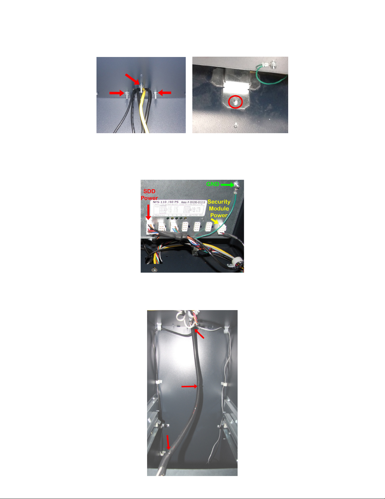
1. Open the Vault. Grasp the cassette handle, RED arrows in Le Image, and pull the cassette out of the dis-
penser. Press the rail latch down, Yel l ow arrow in Right Image, and slide the rails out until fully extended.
2. Loosen the wing nuts, Le Image, but do not remove from post, Right Image.

Triton Systems ©
5
TDN 07103-04303
3. Li the front of the dispenser to pass over the rail edge and slide out enough to reach the power and
communications cable in the back.
4. On the back of the dispenser, loosen the two thumbscrews and remove the communication cable, Le Image.
Disconnect the power cable, Right Image.
5. Remove and set aside the dispenser from the unit. PRIME the cassette and insert into SDD.

Triton Systems ©
6
TDN 07103-04303
6. Disconnect the ground wire from the dispenser tray. Save the screw for later use.
7. Remove the SDD to Security Module Communication cable and SDD to Power Supply cable from four cable
clips. Do not remove the Security Module to main-board communication cable in the clips. Le Image shows
the four cable clips. Right Image shows a close up for clips 1 and 2.
8. Le Image, disconnect the SDD to Security Module communication, RED arrow, and 2-pin power cable,
Ye l l ow arrow, from the security module. Right Image, use the 11/32” nut driver to remove the 11/32” nut,
RED arrow, and washer. Use the small screwdriver to pry apart the bracket and remove the cable.

Triton Systems ©
7
TDN 07103-04303
9. Remove the cable cover under the power supply by rst removing the 3 nuts inside the vault, RED arrows
Le Image, with a 11/32” hollow nut driver. Remove the top screw, Circle in Right Image. Save the bracket,
nuts, and screw for later use.
10. Using the 11/32” hollow nut drive, disconnect the ground wire, RED Arrow. Save the Keps nut for later use.
Disconnect the SDD power plug and Security Module power plug from the power supply. Pull the SDD pow-
er cable, Security Module power cable and ground into lower cabinet.
11. Cut the 3 Ty wraps, RED arrows, from the tubing. Remove the cable and wire from the tubing. Save the
tubing for the upgrade cables.

Triton Systems ©
8
TDN 07103-04303
12. Feed the four-wire MMR050 power cable, Item #2 and ground wire, Item #3 through the vault/cabinet open-
ing. Connect the power cable into the 10-pin socket, RED Arrow. Use the 11/32” hollow nut drive and the
saved Keps nut from step 10 to secure the ground wire to the power supply.
13. Route the dispenser and Security Module power cable through the four clips shown, Le Image. Plug the two
prong plug into the security module, Right Image. Ground cable routed in step-20.
14. Route the data cable from the security module to the MMR dispenser through the clip shown, Le Image.
Loop the data cable up through the top clip and back down through the rst clip, Right Image.

Triton Systems ©
9
TDN 07103-04303
15. Make the Data cable approximately 2 1/2 inches longer than the power cable. TY Wrap the power and data
cables together. Trim excess TY Wrap.
16. Pull the excess Data cable back up to the clips and make a “Bow”, Le Image. Place the excess cable into the
clip, Right Image.
17. Obtain the black tubing used with the SDD cables from step 11. Place the cables into the tubing.

Triton Systems ©
10
TDN 07103-04303
18. TY Wrap the end of the tubing by the clip. Trim excess TY Wrap, Le Image. TY Wrap the tubing at the
opposite end. Trim excess TY Wrap, Right Image.
19. From the kit, obtain clip, Item 6, and slip over the tube. Secure clip to rail using screw, Item 4.
20. Route the ground wire through the back-right clip. Close the clip, Le Image. Continue routing the ground
wire down through the white clip, Right Image.

Triton Systems ©
11
TDN 07103-04303
21. Use the screw from step 6 to attach the ground wire to the tray, Le Image. Place the tubing over the door,
Right Image.
22. Install the cable cover removed earlier. Use extreme caution NOT to pinch any of the cables. Secure cover
with screw removed earlier. Inside of the vault, secure the three nuts with a 11/32” hollow nut driver.
**Note**
May need to disconnect the input power cord to the power supply and remove the power supply by loosening
the two nuts under the power supply, then li up the power supply and set on cabinet oor. Aer securing the
cable cover, install the power supply to cabinet wall.
23. Obtain the MMR050 dispenser and remove the cassette. Using the T20 Torx screwdriver, remove the two
screw, RED arrows, GREEN circles, and install two cable clamps, Item 7, with same screws to the chassis.

Triton Systems ©
12
TDN 07103-04303
24. Place the dispenser on the tray.
25. Plug the power cable into the dispenser, Le Image. Route the data cable behind the power cable and plug
into the dispenser, Right Image.
26. Bend the clip around the Data cable to keep it in place, Le Image. Bend the back clip over and down the
tubing. Tuck the end in behind the metal ange, Right Image.

Triton Systems ©
13
TDN 07103-04303
27. Verify the dispenser is behind the tray tab RED arrow, Le Image. Secure dispenser with the two wing nuts,
Right Image.
28. Install the cassette and push dispenser in, until the rail latch clicks, Le Image. Move the tray in and out
several times to ensure the cables will not bind or interfere with any moving parts. If no cable binding, push
the tray until the rail latches the tray in, Right Image.
29. Open the control panel and plug the input power cord into the power supply. Turn the power supply on.
If the POST screen displays Found Dispenser MMR050 2016-02.D3, continue to management functions to
congure ATM.
30. If the ATM does not nd the dispenser, as shown below, the opening screen should have error code 363.
Open the Management Functions screen and continue to next step.

Triton Systems ©
14
TDN 07103-04303
31. Navigate to Management Functions > Diagnostics (2) > Cash Dispenser (4) > Initialize Dispenser (7).
32. e Initialize Dispenser screen will request conrmation to initialize the dispenser. Press the Enter button
to continue. Initialization will take several minutes. Should hear the dispenser cycle before seeing the
Dispenser Initialization complete screen. Press the Enter button to continue.
33. Navigate to Management Functions > Diagnostics (2) > Dispenser (4) > Cassette Parameters (8).
34. Select the Multiple Amount (8) to set the denomination in the active cassette.
35. Press the Enter button on the warning prompt. Remove cassette from dispenser, then press the Enter button.

Triton Systems ©
15
TDN 07103-04303
36. Load notes not in cassette. Insert cassette into dispenser, then press the Enter button.
37. e dispenser cycles a note into the Reject cassette.
38. Denomination is the type of note loaded ($5, $10, $20 etc.). Use the on-screen numeric keypad to enter the
denomination of notes loaded. Press the Enter and Return button to save the value. e screen will return to
the Cassette Parameter menu.
39. Press the Save and Return button to return to the Cassette Dispenser Diagnostics menu.
40. Press the Exit Management Functions button and return ATM for customer use.
E MMR P

Triton Systems ©
16
TDN 07103-04303
Table of contents
Other Triton Industrial Equipment manuals