manuals.online logo
Brands
  1. Home
  2. •
  3. Brands
  4. •
  5. Trol Systems
  6. •
  7. Control Unit
  8. •
  9. Trol Systems MCU-04-115 User manual

Trol Systems MCU-04-115 User manual

Installation guide for part number:
MCU-04-115
T6T6
T6T6
T6
T6 is a trade name of Trol Systems Inc.
TSI reserves the right to make changes to the information contained in this manual without notice.
publication MCU115- rev:5 | © 2003 TSI All rights reserved | printed in USA
Main
Control
Unit
Specifications for: MCU-04-115
Power Requirements:
115VAC @ .02A, 50/60Hz w/1000v magnetic isolation
Outputs:
4 normally open relay contacts unprotected, no leakage current
5Amps @ 230VAC ( resistive load ), 250 VA ( inductive load ).
Response time: 10ms operate / 5ms release
Rated life: 5 million ( mech ) / 200,000 @ 3A ( resistive load )
Inputs:
6 self powered, 12-14 VDC @ 10ma. w/ 1000v optical isolation.
Maximum leakage of input device: 0.5ma
Response time: all are factory set at 10ms, the user may change
any input to between 0 to 255ms using the Setup Menu.
Auxiliary Supply:
10 - 14vdc @ 100ma., thermal overload protected.
Physical:
Size 2.9” ( 75mm ) x 2.2” ( 55mm ) x 4.3” ( 110 mm )
Mounting DIN rail or panel ( with two #6 screws )
Weight 10 oz. ( 284 grams )
Temp 0 - 140°F, 90% r. humidity ( no condensation )
Origin Designed and assembled in the USA.
CommunicationPorts:
Expansion Twin RJ-11, IIc bus @ 100khz max.
PC Prog. 3.5mm, RS-232C @ 19200 Hi / 9600 Lo
Visit our web site at www.trolsystems.com for
latest information about the T6 control system.

Wiring the supply:
TheT6MCUrequiresa115VAC supply. It is good practice for the supply to
be fused. Connect the supply to the two terminals marked “115VAC” on
output side of unit, as shown below.
Wiring the outputs:
Each output consists of a normally open relay contact that can switch up to
5amps at230vac. These contactsshare acommon terminalmarked“COM”.
If the loads are the same voltage as the supply, install a jumper to the “Hot”
side of the 115vac as shown below. If the loads require a different voltage
than the supply, connect the common terminal of the outputs to a power
supply suitable for the load devices.
Noisetransients, causedwhenan inductiveloadis de-energized,maycause
erraticbehavior of electronic equipment as well as greatly shorten the life of
relay contacts. The use of a load suppressor, is recommended ( see the
OptionalEquipment booklet ). Below is a typical 115vac load configuration.
black
LOADS
(115 vac) 115 vac
(“Hot”)
Common
(“Cold”)
white
5amp Fuse
black
Wiring the Inputs:
The inputs of the T6 are self-powered and optically isolated to offer high
noise immunity. The input voltage is +12vdc, which allows the inputs to
interfacetoa wide variety of switches and sensors. The device wired to the
input must be able to carry a minimum current of 10 milliampere. Input
devices are wired between the input number and either of the two common
terminals on the input side of the unit. This is illustrated below.
Warning!The inputsare self-poweredandcan bedamagedif connected
to an outside power source! Use a converter block ( see the Optional
Equipment booklet ) if the input device is not of a dry contact or of a
sinking configuration as required.
Electromechanical devices such as mag-
netic reed switches, limit switches, push but-
tonswitches and pressure switches are wired
withno regard to polarity ( positive/negative ).
Electronic devices such as magnetic hall ef-
fect transistors, photo-transistors, and DC
proximitysensors must meet the following cri-
teria:
-It must be of an open collector NPN ( like
symbol in illustration ). This is often referred
to as being in a sinking configuration.
-It cannot have an off current ( leakage )
greater than .5 ma ( .005 amp ).
-It must NOT be of a PNP or sourcing con-
figuration.
Note on three wire sensors:
The Auxiliary DC power supply terminal can
be used to support sensors that require up to 100ma of current. If more
current is needed, an external DC power supply is required ( see optional
equipment manual ). The Auxiliary supply measures between 10-14 volts,
which is suitable for most 3 wire proximity sensors.
switch
3wire prox.
sensor
POS
OUT NEG
Note: An MCU-04 can be used as a direct replacement of a MCU-01 to
MCU-03 controller. It has an additional Auxiliary power supply terminal.
Note: The T6 Optional equipment manual is available on-line at
www.trolsystems.com. In the literature index choose to download the T6
Optional Equipment booklet.
This manual suits for next models

1

Popular Control Unit manuals by other brands

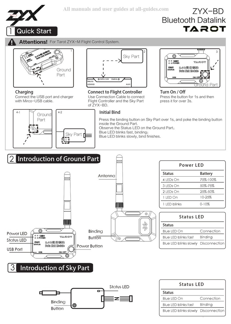
Tarot ZYX-BD quick start

Tarot

Tarot ZYX-BD quick start

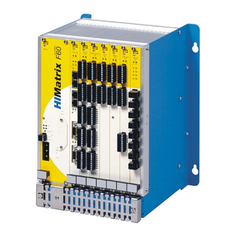
HIMA DIO 24/16 01 manual

HIMA

HIMA DIO 24/16 01 manual

Genebre 2231 Installation, operation and maintenance manual

Genebre

Genebre 2231 Installation, operation and maintenance manual

Brocade Communications Systems 6542 Hardware reference manual

Brocade Communications Systems

Brocade Communications Systems 6542 Hardware reference manual

Ring Engineering LM-4S-G user manual

Ring Engineering

Ring Engineering LM-4S-G user manual

Infineon XMC1000 Getting started

Infineon

Infineon XMC1000 Getting started

CEAG GHG 411 operating instructions

CEAG

CEAG GHG 411 operating instructions

Flexball Series 3500 Operating manual  & installation guide

Flexball

Flexball Series 3500 Operating manual & installation guide

Cumberland Var-O-Matic installation instructions

Cumberland

Cumberland Var-O-Matic installation instructions

Toa SP-11N manual

Toa

Toa SP-11N manual

HEIDENHAIN TNC 370 user manual

HEIDENHAIN

HEIDENHAIN TNC 370 user manual

HHC CH18 instructions

HHC

HHC CH18 instructions

Bolymin BEGV643A Series user manual

Bolymin

Bolymin BEGV643A Series user manual

Thyracont VD12 operating instructions

Thyracont

Thyracont VD12 operating instructions

Allen-Bradley 1785-KE user manual

Allen-Bradley

Allen-Bradley 1785-KE user manual

SMC Networks VHK-A Operation manual

SMC Networks

SMC Networks VHK-A Operation manual

Dungs DSLC px Vx Operation and assembly instructions

Dungs

Dungs DSLC px Vx Operation and assembly instructions

Blackrock Microsystems CerePlex E Series Instructions for use

Blackrock Microsystems

Blackrock Microsystems CerePlex E Series Instructions for use

manuals.online logo
manuals.online logoBrands
  • About & Mission
  • Contact us
  • Privacy Policy
  • Terms and Conditions

Copyright 2025 Manuals.Online. All Rights Reserved.