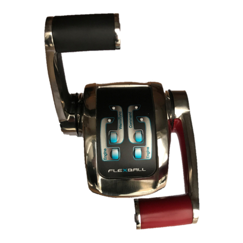
Flexball Series 3500 Specification sheet

Flexball Italiana S.r.l. 1
O
Op
pe
er
ra
at
ti
in
ng
g
m
ma
an
nu
ua
al
l
&
&
m
mo
ou
un
nt
ti
in
ng
g
i
in
ns
st
tr
ru
uc
ct
ti
io
on
ns
s

Flexball Italiana S.r.l. 2
Index
1. Introduction.................................................................................................................................................................... 4
2. General installation features .......................................................................................................................................... 4
2.1. Description of the system and its parts............................................................................................................ 4
2.2. Maximum extension of the system .................................................................................................................. 4
2.3. System performance ....................................................................................................................................... 4
3. Pilot instructions............................................................................................................................................................. 5
3.1. Control keypad ................................................................................................................................................ 6
3.2. Acquisition of the command ............................................................................................................................ 7
3.3. Engine Warm-up ............................................................................................................................................. 7
3.4. Synchro mode ................................................................................................................................................. 8
3.5. Fast Start-up Mode.......................................................................................................................................... 8
3.6. Emergency lever ............................................................................................................................................ 8
4. Command station........................................................................................................................................................... 9
4.1. Dimensions...................................................................................................................................................... 9
4.1.1. Command station series 3500 .................................................................................................................... 9
4.1.2. Command station series 4500 .................................................................................................................. 10
4.2. Friction adjustment ........................................................................................................................................ 10
4.2.1. Command station series 3500 .................................................................................................................. 10
4.2.2. Command station series 4500 .................................................................................................................. 11
4.3. Programming of the command station........................................................................................................... 11
4.4. Command station label.................................................................................................................................. 12
4.5. Command station codes................................................................................................................................12
5. Actuator ....................................................................................................................................................................... 13
5.1. Drawing of actuators with mechanical interface ............................................................................................ 13
5.2. Drawing of full electronic actuator ................................................................................................................. 14
5.3. Actuator labels............................................................................................................................................... 15
5.4. Actuator Codes.............................................................................................................................................. 16
5.5. Electronic Actuator Boards ............................................................................................................................ 17
5.5.1. Actuator board ver. 3.1 ............................................................................................................................. 17
5.5.2. Relays PCB version 1.0 for electronic gearboxes..................................................................................... 18
5.5.3. Relays PCB version 2.0 for electronic gearboxes..................................................................................... 19
5.5.4. CANBus PCB for motor with CANBus interface ....................................................................................... 20
5.5.5. Galvanic insulation PCB for analogue voltage signals................................................................................. 20
6. Accessories and Options ............................................................................................................................................. 21
6.1. CANBus data transmission cable .................................................................................................................. 22
6.2. Cable actuator – electronic motor (V) ............................................................................................................ 22
6.2.1. Nanni Diesel – Throttle cable for Toyota ECU .......................................................................................... 23
6.2.2. Nanni Diesel – Cable only for the inverter (hybrid motors) ....................................................................... 23
6.2.3. Nanni Diesel – Command cable for throttel and inverter (1°part, Y cable)............................................... 23
6.2.4. Nanni Diesel – Y cable for Toshiba motor base (V) + inverter (V) ........................................................... 24
6.2.5. Nanni Diesel – Y cable for VM motor base (CANBus) + inverter ............................................................. 24
6.2.6. FPT – Throttle CANBus command cable.................................................................................................. 25
6.3. Cable actuator – gearbox solenoid driven ..................................................................................................... 25
6.3.1. Nanni Diesel – Cable for gearbox solenoid driven.................................................................................... 25
6.3.2. FPT – Cable for gearbox solenoid driven ................................................................................................. 25
6.3.3. Nanni Diesel – Cable for gearbox solenoid drive + neutral signal............................................................. 26
6.4. Cable actuator – trim/flap .............................................................................................................................. 26
6.4.1. Nanni Diesel – Cable for the trim/flap command ...................................................................................... 26
6.5. Cable actuator – Mercruiser® trim pump....................................................................................................... 27
6.6. T-Splitter........................................................................................................................................................ 27
6.7. Power supply connector ................................................................................................................................ 27
6.8. Trim/Flap option ............................................................................................................................................ 28
7. System types and installation schemes ....................................................................................................................... 29
7.1. Installation with 2 mechanical actuators – solution A .................................................................................... 30
7.2. Installation with 2 mechanical actuators – solution B .................................................................................... 31
7.3. Installation with 2 mechanical actuators – solution C .................................................................................... 32
7.4. Installation with 1 actuator – solution D ......................................................................................................... 33
7.5. Installation with 1 actuator – solution E ......................................................................................................... 34
8. Configuration of the CANBus network: end of line termination resistor and address setting of command stations and
actuators ............................................................................................................................................................................... 35
8.1. Configuration of the command station ........................................................................................................... 35
8.2. Configuration of the actuator ......................................................................................................................... 36
9. Push-pull cables installation ........................................................................................................................................ 38
9.1. Connection kit................................................................................................................................................ 38
9.2. Standard push-pull cable (E2, E3, Volvo®, C0, C3, C33…).......................................................................... 38
9.3. Push-pull cable outgoing from the Mercruiser® stern driver.......................................................................... 39
9.4. Johnson® push-pull cable .............................................................................................................................39

Flexball Italiana S.r.l. 3
10. Electrical installation .................................................................................................................................................... 40
10.1. Wiring of actuator output cables ............................................................................................................... 40
10.1.1. Cabling of the supply connector ............................................................................................................... 40
10.1.2. Electrical installation of systems with 1 motor, 1 actuator and 1 dashboard ............................................. 42
10.1.3. Electrical installation of systems with 2 motors, 1 or 2 actuators and 2 dashboards ................................ 43
10.1.4. Electrical installation of systems with 1 motor, 1 actuator and 2 dashboards ........................................... 44
10.1.5. Dimensional criteria of the power cables for the overall installation.......................................................... 45
10.2. Electrical cabling of the outgoing cables from the actuator....................................................................... 46
10.2.1. Cabling of actuators for mechanical and hybrid propulsion systems ........................................................ 46
10.2.2. Cabling of actuators for electronic propulsion systems............................................................................. 47
10.2.3. Cabling scheme from actuator to gearbox, from actuator to trim or from actuator to flap ......................... 47
11. Programming of the actuator, general guidelines ........................................................................................................ 48
11.1. Programming keypad................................................................................................................................ 48
11.2. Display and Parameters ........................................................................................................................... 48
11.3. Actuator parameters .................................................................................................................................49
11.3.1. Parameter “CC” ........................................................................................................................................ 49
12. Setting of the strokes of push-pull cables .................................................................................................................... 50
12.1. Setting of the stroke of the accelerator cable............................................................................................ 50
12.2. Setting of the stroke of the gearbox cable ................................................................................................ 51
13. Programming of the actuator in installations with mechanical motor and gearbox ...................................................... 52
13.1. Mounting of the push-pull cable................................................................................................................ 52
13.2. Programming of the push-pull cable strokes............................................................................................. 52
13.3. Specific parameters.................................................................................................................................. 53
14. Programming of actuators for installations with electronic motor and mechanical gearbox......................................... 54
14.1. Programming of the gearbox strokes........................................................................................................ 54
14.2. Specific parameters.................................................................................................................................. 54
14.2.1. Parameter A0 ........................................................................................................................................... 55
14.2.2. Parameters to configure the voltage output signal for electronic motors .................................................. 56
15. Programming of actuators for mechanical motors and electronic gearbox .................................................................. 57
15.1 Installation of motor the push-pull cable and programming of throttle mechanical strokes............................ 57
15.2 Programming of the push-pull cable strokes ................................................................................................. 57
15.3 Electrical cabling of the gearbox....................................................................................................................57
15.4 Specific parameters....................................................................................................................................... 57
16. Programming of actuators with electronic motor and electronic gearbox..................................................................... 58
16.1. Electrical wiring......................................................................................................................................... 58
16.2. Specific parameters.................................................................................................................................. 58
17. Programming of actuators with electronic CANBUS motor and mechanical gearbox.................................................. 59
17.1. Installation of the push-pull cable and programming of the cable stroke .................................................. 59
17.2. Specific parameters.................................................................................................................................. 59
17.2.1. CANBus protocol ...................................................................................................................................... 59
17.2.2. Setting of the CANBus parameter values ................................................................................................. 60
17.2.3 Technical data of the CANBus interface card........................................................................................... 61
17.3. Wiring of the outgoing actuator cables ..................................................................................................... 61
17.4. Connection to FPT motors through CANBus interface ............................................................................. 61
18. Programming of actuators with electronic CANBUS motor and electronic gearbox.................................................... 63
18.1. CANBus motor parameters....................................................................................................................... 63
18.2. Electronic gearbox parameters................................................................................................................. 63
18.3. Wiring of the actuator outgoing cables ..................................................................................................... 63
19. Programming of actuators for installations with Trim or Flap command option............................................................ 63
20. Programming of actuators with the option for hybrid motors........................................................................................ 64
21. Behaviour of the electronic system in case of failures ................................................................................................. 65
21.1. Unforeseen motor switching off ................................................................................................................ 65
21.2. Faults in the electrical network ................................................................................................................. 65
21.3. Protection in case of overload or break of the push-pull cables................................................................ 65
21.4. Troubleshooting ........................................................................................................................................ 66
21.5. LED diagnosis on command station ......................................................................................................... 67
22. How to start ................................................................................................................................................................. 68
23. Drilling mask ................................................................................................................................................................ 69
Version June 2011

Flexball Italiana S.r.l. 4
1. Introduction
This manual describes the electronic remote control system in general and its operating, performance and
safety aspects. If it is the first time that you install an electronic control system, go to section 22 where you will
be guided to the necessary steps.
2. General installation features
2.1. Description of the system and its parts
The electronic engine remote control implements mechanical and electronic solutions with digital
communication technology. Only few devices are required to compose a complete electronic engine remote
control:
•Commandstations
•Actuators
•Datacommunicationcableswhichconnectthecommand stations to the Actuators
2.2. Maximum extension of the system
The maximum configuration of the system is as shown in the following table:
Actuators The maximum number of engines that the system can control is 2
Command stations The maximum number of command stations in the installation is 3
80 meters Maximum distance between cockpit and engine room
2.3. System performance
Temperature
Operating temperature From -10 to 85°C
Storage temperature From -40 to 90°C
Mechanical features
Nominal load when actuator is providing a
pushing force 150 N (15 kg) with power consumption 1.5 A
Max load when actuator is providing
a pushing force 450 N (45 kg) with power consumption 5 A (with time <1 s)
Stroke of gearbox – forward
Stroke of gearbox – reverse Stroke can be set to between 5 and 40 mm
Throttle stroke Stroke can be set to between 5 and 80 mm
Electrical features
Power supply (*) from 9,0 to 16 Vdc or from 9,0 to 28,0 Vdc
Max. current absorbed 5 A
Current absorbed when the system isn’t loaded 0,5 A
* according to the version of the actuator

Flexball Italiana S.r.l. 5
3. Pilot instructions
Each station can be programmed for the control of one or two engines. Each lever repeats the functionality of a
traditional mechanical lever.
Moving the lever from the neutral position, after 16° forward or reverse automatically the electronic system
clutches-in respectively the forward or reverse gear. The accelerator lever has a stroke of 62° both in forward
and backward direction.
Command station series 3500
Command station series 4500

Flexball Italiana S.r.l. 6
3.1. Control keypad
On the command station it is mounted an electronic keypad with 4 push-buttons and 4 LEDs.
(*) In installations with single engine, both the green LEDs are referring to the same engine. In systems with 2
engines the push button and the green LED on the right are referring to the starboard engine while the push
button and the green LED on the left side are referring to the port engine.
Description LEDs colour
Engine (*) Green
Warm/Sync Orange
Command Red
Engine (*) Green
Command station series 3500 Command station series 4500

Flexball Italiana S.r.l. 7
It follows the table with the definition of LED and push buttons.
Push-button LED Description
(Command) (Meaning)
Engine
The left LED is for the port (left) engine, while the right LED is for the
starboard (right) engine. If the LED has a fixed light on (green), the
corresponding gearbox is in neutral position.
If the LED is blinking (green), the lever on the LED’s side is synchronised
with the lever of the station that at the moment has the Command.
Command
If it is switched off, the Station has not the command.
If is switched on, the Station has the command.
Warm/Sync
If it is blinking, the navigation system is in Warm-up mode; this means that
the engines can be warmed up without clutching-in the gear.
If the LED is fix lighted, the system is in Synchro mode
Warm/Sync
When both the levers of the Station that has the command are in neutral
position, if you press for 1,5 seconds the button Warm, it is activated the
function Warm-up.
Command
If you press Command for 1,5 seconds the station takes the command, only
if one of these two conditions are respected:
- both the lever of the station are in neutral
- both the lever are synchronized with respect to the levers of the station
that at the moment has the command
All LEDs are lighted on The control system isn’t working correctly
3.2. Acquisition of the command
It is possible to acquire the command of the boat from any Station in the following cases:
The boat isn’t moving
1. Position all the levers in neutral and press Command for 1,5 seconds.
2. LED “Command” is now lighted on while the warm/synch LED is blinking. You are in Warm-up mode:
throttle command is enabled but clutch command is disabled.
3. To take the command you must press for 1,5 seconds the Warm/Sync bush-button, afterwards the
station acquires the command.
In navigation
1. Synchronize the 2 levers of the Station which wants to acquire the command with respect to the Station
which has the command.
2. When LEDs “Engine” of two levers of the station which wants to acquire the command are blinking,
these levers are synchronised with respect to the levers of the Station which still has the command.
3. By pressing the pushbutton Command for 1,5 seconds, the new Station takes the command.
►Important: before taking the command, proof that all the passengers are safely on board.
3.3. Engine Warm-up
If both levers are in neutral, by pressing for 1,5 seconds the button Warm/Sync of the Station which has the
command, you enter in Warm-up mode. If you move the lever. it is only affected the accelerator but not the
gear. In Warm-up mode the LED Warm/Sync is blinking.
After positioning again both levers in neutral and pressing for 1,5 seconds the Warm/Sync, the system comes
back to the normal operation mode.

Flexball Italiana S.r.l. 8
3.4. Synchro mode
It is possible to command both engines at the same speed and direction with only one lever. This function can
be activated only by the command station which has the command.
With both levers in neutral position, press at the same time for 1,5 seconds the two “engine” push-buttons. The
command of both engines is now on the right lever. In Synchro operation mode, the LEDs “Warm/Sync” and
“Command” are lighted on.
From “Synchro” operation mode, if you position both levers in neutral, and press contemporaneously for 1,5
seconds the two “Engine” push buttons, the command of each engine is again assigned to the respective lever
and LED “Warm/Sync” is switched off.
The same operation of synchronisation or de-synchronisation can be performed on the station which has the
command, in case the RPM between the two motors doesn’t differ more than 10%.
3.5. Fast Start-up Mode
This function is available on the first command station as described in section 8.1 of this manual. When the
configuration FSM (Fast Start up Mode) is enabled, the command station with the FSM enabled takes
automatically the command at the power on, only if this command station is in neutral position.
If the command station is not in neutral position, the command station will take the command as soon the
neutral position will be reached.
3.6. Emergency lever
In case of emergency, the electronic system can be
switched off quickly and the engines can be operated
directly with the mechanical emergency levers.
Emergency levers are fitted on the control box. It is
sufficient to turn completely on (clockwise) knob (A).
After this operation, the gearbox can be operated
manually using levers (B) and with the throttle set to
minimum.
In order to reset the system, turn off completely
(counter-clockwise) knob (A). The emergency lever
automatically goes back to the position where it was
before activating the emergency mode, at the first
movement of the command lever.
B
A

Flexball Italiana S.r.l. 9
COMMAND
ENGINE 2
WARM/S
ENGINE 1
4. Command station
Command stations are classified as devices for the control of one or two engines, with or without trim/flap
command. Up to three command stations can be mounted in the same installation. Depending on the
application, it is very important to set the dip-switches present on the bottom part of the command station, as
described in sections 4.2 and 8.1 of this manual.
4.1. Dimensions
4.1.1. Command station series 3500
►Important: in case the screws to fix command station to the dashboard panel are not long enough, don’t
open the command station to replace them but ask for an adaptation kit.

Flexball Italiana S.r.l. 10
4.1.2. Command station series 4500
4.2. Friction adjustment
4.2.1. Command station series 3500
To adjust the inner friction of the command lever, remove the
PVC cap (A) and unscrew the fixing screw. It is possible to
adjust the friction screwing and unscrewing the inner screw
placed into the hole (B). When the regulation will be done,
mount the screw and the plastic cap.
►Important: in case of command station for one engine,
the friction is placed under the right command lever.

Flexball Italiana S.r.l. 11
4.2.2. Command station series 4500
In order to adjust the friction of the lever, it is necessary to remove the screw A
placed below the plastic base of the command station. With the help of an
hexagon screw driver size 3 mm you can loosen or tighten the screw and the
friction will become correspondingly softer or harder.
Once the friction has been adjusted, close again the hole with screw A.
Important: In case of a command station for single engine, the friction is
present only on the left lever.
4.3. Programming of the command station
At power up, the command station makes a sequence of two flashes. The first flash identifies the number of
motors and the second identifies the number of actuators present in the system. According to the length of
each flash, the command station is differently configured.
You need to configure the command station in relation to the type of installation. It is also possible to modify the
configuration of the command station by keeping pressed before powering up and continuing to keep them
pressed for 6 seconds after power up, the following push buttons:
thetwointernalpushbuttons(Warn/Sync+Command), in this case you modify the number of
actuators
(Engineleft+Engineright),inthiscaseyouchange the number of motors on the boat
Possible configurations are according to the following table:
1°flash
(identifies the number of motors)
2°flash
(identifies the number of actuators)
Installation with 1 motor
and 1 actuator Long (3 seconds) Long (3 seconds)
Installation with 2 motors
and 1 actuator Short (less than 1 second) Long (3 seconds)
Installation with 2 motors
and 2 actuators Short (less than 1 second) Short (less than 1 second)
►Important: from the factory, the command station is configured with the first flash short and the second flash
long.
1. To configure the command lever for an installation with 2 actuator boxes, press the two central push
buttons (Warm/Sync e Command) before powering up the command lever and continue to keep them
pressed for 6 seconds. The lever is now configured for installations with two motors and two actuators.
At the next normal power up, the command lever will make a sequence of 2 short flashes.
2. In case you need to configure again the command lever for installation with 2 motors and 1 actuator,
repeat the procedure of point 1.
B

Flexball Italiana S.r.l. 12
4.4. Command station label
Under the base of the command station it is present the following
label.
This labels indicates the code of the command station, the serial
number and the different dip-switches configuration according to the
type of the command station.
►Important 1: these configurations are valid according to schemes
from section 7.1 to t.5. in case of different configurations, contact the
constructor technical department
►Important 2: in the same installation can’t coexist a “1st command
station FSM” and a “1st command station”. “1st command station
FSM” replaces “1st command station” and vice versa.
4.5. Command station codes
Command stations
Descrizione Code
Command station 1 motor series 3500 3500
.
C
-
1
0
0
0
0
5
Command station 1 motor series 3500 with TRIM option 3500
.
C
-
1
1
0
0
0
5
Command station 2 motors series 3500 3500
.
C
-
2
0
0
0
0
5
Command station 2 motors series 3500 with TRIM option 3500
.
C
-
2
2
0
0
0
5
Command station 1 motor series 4500 4500
.
C
-
1
0
0
0
0
5
Command station 1 motor series 4500 with TRIM option 4500
.
C
-
1
1
0
0
0
5
Command station 2 motors series 4500 4500
.
C
-
2
0
0
0
0
5
Command station 2 motors series 4500 with TRIM option 4500
.
C
-
2
2
0
0
0
5
Command station 1 motor series 4500 with Trolling option 4500
.
T
-
1
0
0
0
0
5
Command station 1 motor series 4500 with TRIM option & Trolling 4500
.
T
-
1
1
0
0
0
5
Command station 2 motors series 4500 with Trolling option 4500
.
T
-
2
0
0
0
0
5
Command station 2 motors series 4500 with TRIM option & Trolling 4500
.
T
-
2
2
0
0
0
5

Flexball Italiana S.r.l. 13
5. Actuator
The actuator should be mounted in the engine room in a safety place but as near as possible to the propulsion
engine. With reference to the type of motor and gearboxes, with or without trim/flap, actuators are classified as
follow:
mechanical
electronic
mechanical&electronic(hybrid)
It follow mechanical drawings of the different types of actuators. The last page of this manual you find the
footprint of the actuator in scale 1:1.
5.1. Drawing of actuators with mechanical interface
►Important: the part of the drawing identified with letter (A) doesn’t exist on actuators with mechanical
interface either towards the motor or towards the gearbox.
A

Flexball Italiana S.r.l. 14
5.2. Drawing of full electronic actuator
LEFT ENGINE RIGHT ENGINE
+12 V
Fuse
CANBus
How to mount the actuator
Do not install the actuator with the
connectors upwards
Mount the actuator leaving a space of at least 25 cm on each side

Flexball Italiana S.r.l. 15
5.3. Actuator labels
Inside the actuator there are two labels indicating code and serial number. Please write them down in case you
call for assistance.
Ac
tuator
code
Serial number

Flexball Italiana S.r.l. 16
5.4. Actuator Codes
Actuator for 1 mechanical motor and 1 gearbox mechanical (no trim) 3500
.
A
-
0
0
4
0
3
9
Actuator for 1 mechanical motor and 1 gearbox mechanical (with trim) 3500
.
A
-
0
0
4
1
3
9
Actuator for 1 electronic motor (V) and 1 gearbox mechanical (no trim) 3500
.
A
-
1
1
4
0
3
9
Actuator for 1 CANBus motor and 1 gearbox mechanical (no trim) 3500
.
A
-
5
1
4
0
3
9
Actuator for 1 electronic motor (mA) and 1 gearbox mechanical (no trim) 3500
.
A
-
7
1
4
0
3
9
Actuator for 1 PWM motor and 1 gearbox mechanical (no trim) 3500
.
A
-
3
1
4
0
3
9
Actuator for 2 electronic motors (V) and 2 gearboxes mechanical (no trim) 3500
.
A
-
2
2
4
0
3
9
Actuator for 2 motors CANBus and 2 gearboxes mechanical (no trim) 3500
.
A
-
6
2
4
0
3
9
Actuator for 2 electronic motors (mA) and 2 gearboxes mechanical (no trim) 3500
.
A
-
8
2
4
0
3
9
Actuator for 2 PWM motors and 2 gearboxes mechanical (no trim) 3500
.
A
-
4
2
4
0
3
9
Actuator for 1 electronic motor (V) and 1 gearbox mechanical (with trim) 3500
.
A
-
1
1
4
1
3
9
Actuator for 1 CANBus motor and 1 gearbox mechanical (with trim) 3500
.
A
-
5
1
4
1
3
9
Actuator for 1 electronic motor (mA) and 1 gearbox mechanical (with trim) 3500
.
A
-
7
1
4
1
3
9
Actuator for 1 PWM motor and 1 gearbox mechanical (with trim) 3500
.
A
-
3
1
4
1
3
9
Actuator for 2 electronic motors (V) and 2 gearboxes mechanical (with trim) 3500
.
A
-
2
2
4
2
3
9
Actuator for 2 CANBus motors and 2 gearboxes mechanical (with trim) 3500
.
A
-
6
2
4
2
3
9
Actuator for 2 electronic motors (mA) and 2 gearboxes mechanical (with trim) 3500
.
A
-
8
2
4
2
3
9
Actuator for 2 PWM motors and 2 gearboxes mechanical (with trim) 3500
.
A
-
4
2
4
2
3
9
Actuator for 1 mechanical motor and 1 gearbox solenoid driven (no trim) 3500
.
A
-
0
3
4
0
3
9
Actuator for 2 mechanical motors and 2 gearbox solenoid driven (no trim) 3500
.
A
-
0
3
4
0
3
9
Actuator for 1 mechanical motor and 1 gearbox solenoid driven (with trim) 3500
.
A
-
0
3
4
1
3
9
Actuator for 2 mechanical motors and 2 gearbox solenoid driven (with trim) 3500
.
A
-
0
3
4
2
3
9
Actuator for 1 electronic motor (V) and 1 gearbox solenoid driven (no trim) 3500
.
A
-
1
3
0
0
3
9
Actuator for 1 CANBus motor and 1 gearbox solenoid driven (no trim) 3500
.
A
-
5
3
0
0
3
9
Actuator for 1 electronic motor (mA) and 1 gearbox solenoid driven (no trim) 3500
.
A
-
7
3
0
0
3
9
Actuator for 1 PWM motor and 1 gearbox solenoid driven (no trim) 3500
.
A
-
3
3
0
0
3
9
Actuator for 2 electronic motors (V) and 2 gearboxes solenoid driven (no trim) 3500
.
A
-
2
4
0
0
3
9
Actuator for 2 CANBus motors and 2 gearboxes solenoid driven (no trim) 3500
.
A
-
6
4
0
0
3
9
Actuator for 2 electronic motors (mA) and 2 gearboxes solenoid driven (no trim) 3500
.
A
-
8
4
0
0
3
9
Actuator for 2 PWM motors and 2 gearboxes solenoid driven (no trim) 3500
.
A
-
4
4
0
0
3
9
Actuator for 1 electronic motor (V) and 1 gearbox solenoid driven (with trim) 3500
.
A
-
1
3
0
1
3
9
Actuator for 1 CANBus motor and 1 gearbox solenoid driven (with trim) 3500
.
A
-
5
3
0
1
3
9
Actuator for 1 electronic motor (mA) and 1 gearbox solenoid driven (with trim) 3500
.
A
-
7
3
0
1
3
9
Actuator for 1 PWM motor and 1 gearbox solenoid driven (with trim) 3500
.
A
-
3
3
0
1
3
9
Actuator for 2 electronic motors (V) and 2 gearboxes solenoid driven (with trim) 3500
.
A
-
2
4
0
2
3
9
Actuator for 2 CANBus motors and 2 gearboxes solenoid driven (with trim) 3500
.
A
-
6
4
0
2
3
9
Actuator for 2 electronic motors (mA) and 2 gearboxes solenoid driven (with trim) 3500
.
A
-
8
4
0
2
3
9
Actuator for 2 PWM motors and 2 gearboxes solenoid driven (with trim) 3500
.
A
-
4
4
0
2
3
9

Flexball Italiana S.r.l. 17
5.5. Electronic Actuator Boards
5.5.1. Actuator board ver. 3.1
Position on board Pin Description Output cable
1 Vdc
JP8
Supply 2 GND Wall connector
2 V_out CH1
3 V_out CH2
1 GND CH2
JP9
Engine DX
4
MOD2
(Rev.3)
GND CH1
4 poles
2 V_out CH1
3 V_out CH2
1 GND CH2
JP10
Engine SX
4
MOD2
(Rev.3)
GND CH1
4 poles
►Important: channels 1 and 3 are dedicated to the electronic engine (ECU) while the channels 2 and 4 are
dedicated to the inverter for electric motors (hybrid motor applications).
JP12
UP
DOWN ENTER
JP1
JP2
JP7
Fusibile
JP13
JP11
JP14
JP15 JP19
21
JP8 JP3 JP18 JP17 JP16
JP10 JP9 JP6 JP5

Flexball Italiana S.r.l. 18
5.5.2. Relays PCB version 1.0 for electronic gearboxes
Relè right
gearbox
Relè right
gearbox Solenoid gearbox Trim command
1.1 5.1 Forward (brown) Trim “-“ (nero)
1.2 5.2
1.3 5.3 Vdc (yellow/green) Vdc (brown)
2.1 6.1 Reverse (blue) Trim “+” (grey)
2.2 6.2
2.3 6.3
3.1 7.1 Trim “–“ (brown) Trailer (yellow/green)
3.2 7.2
3.3 7.3 Vdc (yellow/green)
4.1 8.1 Trim “+” (blue)
4.2 8.2
4.3 8.3

Flexball Italiana S.r.l. 19
5.5.3. Relays PCB version 2.0 for electronic gearboxes
Fuse
Fusibile
123456789101112 242322212019181716151413
Pin Description
1 Vdc
2 GND
3 Vdc
4 GND
5 Left engine – Trim common contact
6 Left engine – Trim +
7 Left engine – Trim -
8 Left engine – Trailer
9 Left engine - Common neutral relays contact
10 Left engine - NC contact neutral relays
11 Left engine – Forward gear
12 GND
13 Left engine – Reverse gear
14 GND
15 Right engine - Forward gear
16 GND
17 Right engine - Reverse gear
18 GND
19 Right engine - Common neutral relays contact
20 Right engine - NC contact neutral relays
21 Right engine - Common trim contact
22 Right engine - Trim +
23 Right engine - Trim -
24 Right engine – Trailer

Flexball Italiana S.r.l. 20
5.5.4. CANBus PCB for motor with CANBus interface
Important: you need a CANBus board per each CANBus engine
The out-coming cable has a length of 3 meters. Maximum current per each
channel is 100 mA. Out signals are protected against short circuit towards
ground and towards power supply.
CANBus termination resistor of 120 ohm is already implemented on the
PCBoard but, if necessary, it can be removed.
5.5.5. Galvanic insulation PCB for analogue voltage signals
This option can be used in those cases where there are voltage differences between different ground points on
the boat. A non optimum ground network can generate circuit currents and therefore disturbances in the
transmission of command signals (see section 10.1.5.).
Each PCB performs the galvanic insulation of 2 command signal up to 250 Vdc. On each actuator it is possible
to mount 2 PCBs for the interface towards:
ElectronicECUwithvoltagesignal
ElectronicECUwithCANBusinterface
Commandofhybridmotorsfrequencyconverterdriven through a voltage signal
The PCB is mounted inside of the actuator and there aren’t any special precaution to follow durig
commissioning.
terminal
block
Terminal
n° description wire colour Kind of cable
4 Can_H White
JP4 5 Can_L Blue 2 poles
J3 J1 J4
16543212 1
23456
This manual suits for next models
2
Table of contents
Other Flexball Control Unit manuals
Popular Control Unit manuals by other brands
MASCOT
MASCOT VFlo Installation, operation & maintenance instructions
Velleman
Velleman VMM005 user manual
Kessel
Kessel Aqualift F Comfort 400V Series MANUAL FOR INSTALLATION, OPERATION AND MAINTENANCE

Trikdis
Trikdis G10 user manual
Apollo Valves
Apollo Valves DC4A Installation, operation & maintenance manual
LiteOn
LiteOn WN6508A user manual
