TROMOX UKKO S 2022 User manual

Owner’s Manual
* The graphic illustrations in this manual may not reflect exact appearance of actual products
* Specifications subject to change without notice , so as improvement of quality and performance of product.
Please read this manual carefully
before riding and keep it properly.
www.tromox.com

1.The pictures, technical information, data, instructions and other information contained
in this manual have been checked as necessary before it is printed. However, in order to
continuously develop and improve the product, and make this manual meet customers’
demands, we reserve the right to make changes as necessary without further notice.
2.Copy, store or transcribe any content in this manual in any text or document without the
wrien authorization and permission of Hangzhou Tromox Technology Co., LTD is
forbidden and illegal.
3.The corresponding spare parts and accessories of Hangzhou Tromox Technology Co.,
Ltd. are independently designed and purchased, which are applicable to your vehicle under
any circumstances. Please be sure to use the original genuine parts. Tromox will not
guarantee the suitability and safety of the spare parts and accessories that are not
produced by our company, and has no obligation to any loss caused by the use of spare
parts and accessories that are not produced by our company.
Declaration:
Congratulations and thank you for purchasing Tromox models and related services.
In this manual, the basic operation and maintenance of Tromox MS4000D, and MS2500DQ electric
two-wheeled motorcycle and Tromox are introduced in details. Please read this manual carefully before
riding.
The correct operation and maintenance can eectively ensure the safe riding, best performance of
electric motorcycle and prolong its service life.
Our distributors have the technical teams trained by Tromox, who can provide the best maintenance and
services for you.
The data, specifications and instructions in this manual are determined according to the current design,
and the right of changing and interpretation belongs to Hangzhou Tromox Technology Co., Ltd. For the
future technical changes to this electric motorcycle, please refer to our website:
www.tromox.com or “TROMOX UKKO” APP information update.
Wish you a safe journey!
Foreword

For the safety of yourself and others, please obey the following instructions:
1. Before riding, please take your time to carefully read and fully understand all the information in this manual, not
limited to instructions, aention points, and warning information; please thoroughly check whether all components
are in good conditions. If you find any problem, make sure to contact Tromox distributor or authorized service shop
right away.
2. Don’t aempt to operate the vehicle until you have aained adequate knowledge of the operation features,
warnings and cautions.
3.Please thoroughly check the warning labels of the vehicle.
4.It is strictly prohibited to refit, disassemble or change the circuit of this motorcycle. If any repairing or replacement
is required, please only use Tromox approved parts and accessories from our distributors or authorized service shops.
5.Please reserve this operation manual properly.
1.Ones that are not subjected to formal training or without license are strictly forbidden to drive this motorcycle.
2.Please wear the approved helmet produced by the reliable manufacturers while riding to reduce the risk of potential
injury.
3.MS4000D/MS2500DQ can be used for maximum two passengers.
4.Please don’t ride this electric motorcycle when you are drunk, tired, feeling unwell or after taking any medicine that
may aect your driving ability.
5.Loading capacity includes carriage of passenger, luggage or accessories must be in accordance with the local
corresponding laws or regulations, so as to avoid the danger initiatively.
6.In case of rainy and snowy weather or on wet and slippery roads, the braking distance would be longer, please slow
down and don’t brake suddenly to avoid collapse. In addition, don’t ride this electric motorcycle under bad weather
conditions such as storms and typhoons.
User Instructions
Safety Instructions
Table of Contents
User Instructions
Safety Instructions
MS4000D and MS2500DQ Technical Specifications
Instructions for Use
■ Exploded Views of Vehicle Parts
■ Name plate&Position of vehicle
Identification Number
■ Dash Seings
■ Left Handlebar Controls
■ Right Governor Handlebar controls
■ Tires
■ Chain sprockets,Chain,and tightness degree
■ Belt pulley, Belt, and Tightness Degree
03
04
05
06
06
09
10
11
11
11
12
13
■ Use, Maintenance & Installation of Baery
■ Use of Charger
■ Anti-theft Alarm & NFC Start
■ Remote control instructions
■ TROMOX APP
Operational Guidance
■ Pre-ride Inspection
■ Vehicle operation
Maintenance
Troubleshooting
After-sales Service
■ After-sales Service and Warranty Information
■ Limited Warranty
Electrical Schematic Diagram
14
19
20
21
22
27
27
28
32
35
36
36
38
40
03

7.On the road with poor lighting, please turn on the headlight to ensure the safety of yourself and others; if the electric
motorcycle has to be pushed due to low baery, the emergency flashers must be turned on.
8.If the vehicle will not be used for several days, please turn o the air switch in advance to prevent the baery from
being discharged.
9.When leaving the electric motorcycle, please make sure to turn it o and keep it away from the small children.
10.Since this vehicle is powered with lithium-ion baery, please obey the following safety principles to avoid accident:
10.1 Please don’t park the vehicle in the building entrance hall, emergency escape, corridor or exit.
10.2 The vehicle shall not be parked or charged in the residential buildings, and shall be kept away from combustible
materials during charging. Please disconnect the charger as soon as the baery is fully charged.
10.3 Please use the baery properly and pay aention to its warning labels. The waste baery must not be disassem-
bled, but should be sent to the related professional companies for recycling.
10.4 Please read and understand the safety and warning terms of the charger. The replaced charger should match the
baery model.
10.5Please read and understand the cleaning instructions.
11.Items checked before riding:
11.1 Check whether the headlight, turn signal light, tail light, brake light, license plate light and horn are in normal
condition.
11.2 Check whether the front and rear brakes perform normally, whether the fixing bolts of brake caliper are tightened
and whether the power will cut o when user presses the brake.
11.3 Check whether the tire pressure is normal.
11.4 Check whether the handlebars and front & rear wheels are fastened.
11.5 Check whether the reflectors are damaged or contaminated.
11.6 Check the rearview mirror: you should be able to clearly see the rear 10 meters range from the rearview mirror by
siing at the driving position.
If there is any abnormality, please seek for the professional maintenance in time.
Safety Instructions
MS4000D and MS2500DQ Technical Specifications
Size (L x W x H)
Wheel base
Curb weight
Maximum loading capacity
Maximum gradeability capacity
Tire specifications
Rim specifications
1855mm x 800mm x 1045mm
1295 mm
110 kg
150 kg
MS4000D:22°
MS2500DQ:15°
Front Tire: 100/80-14
Rear Tire: 120/70-14
Front Rim: MT2.50x14
Rear Rim: MT3.50x14
Item Technical Specification
Nominal voltage
Baery type
Baery specifications
Charging current of charger
Rated power of motor
Controller type
System: 72 V
Lightning: 12 V
Ternary lithium baery
72V55Ah
Standard: 10A
Optional: 15A
MS4000D: 4000 W
MS2500DQ: 2500 W
FOC vector controller
Item Technical Specification
04 05

A B C DEFG H J KI M NL
Left View
A.Front wheel
E.Left decorative lamp
I.Rear shock absorber
M.Rear wheel
B.Front fender
F.Boom shield
J.Left foot pegs
N.Rear cover
C.Front left shock absorber
G.Side stand
K.Rear fender
D.Dashboard
H. Seat cushion
L.Single rocker arm
M NLA B C DEFG KJIH
A.Rear registration plate lamp
E.Right foot pegs
I.Right decorative lamp
M.Head lock
B.Rear camera
F.Charging interface
J.Motor controller
N.Front right shock absorber
C.Tail light
G.Motor
K.Front camera
D.Seat lock
H. Baery compartment
L.Headlight
Right View
06 07
Exploded Views of electric motorcycle Parts (Left Side View)
Instructions for Use
Exploded Views of electric motorcycle Parts (Right Side View)
Instructions for Use
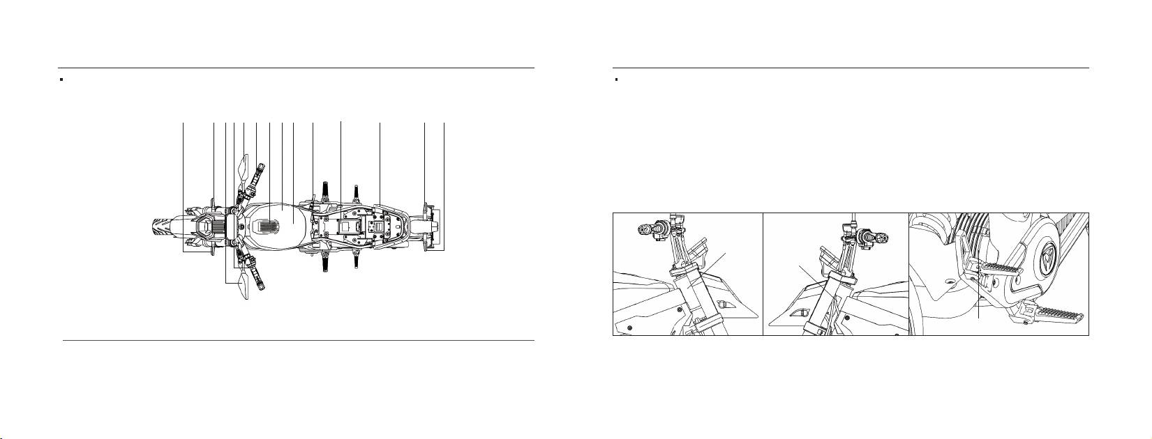
AB C DEFG H J KI M NL
Vertical View
A.Front left turn signal
E.Right rearview mirror
I.NFC
M.Rear right turn signal
B.Front right turn signal
F.Right handlebar switch
J.Air switch
N.Rear left turn signal
C.Left rearview mirror
G.Breathing light
K.VCU
D.Left switch
H. Baery cover
L.Rear handrail
VIN: on the right side of the head tube of the frame
Certification label: on the left side of head tube of the frame
Motor serial number: is etched on the right hand side of the motor
housing and is visible when the motorcycle is fully assembled.
①
②
③
①
②
③
08 09
Name plate & Position of vehicle Identification Number (VIN)
Instructions for Use
Exploded Views of Vehicle Parts (Vertical View)
Instructions for Use

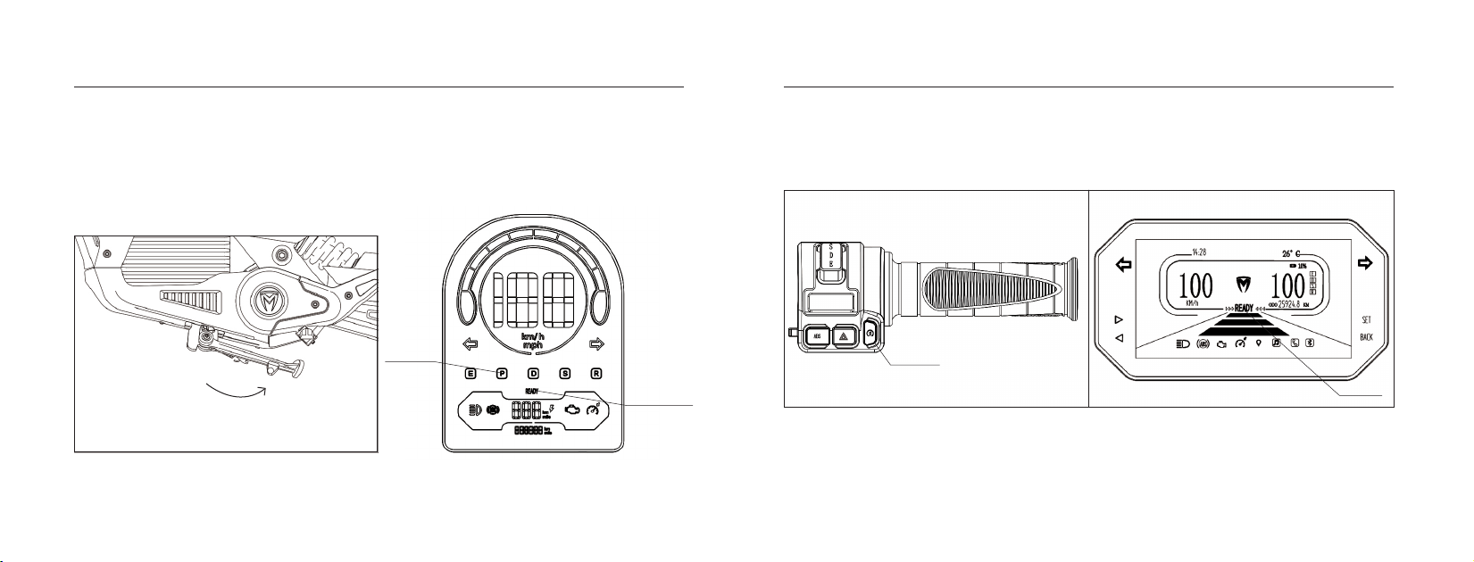
Gear select instructions:
E: Beginner mode: speed 0~30km/h
D: Daily use mode: speed 0~60km/h
S: Sport mode: speed 0~Max.
TFT dashboard VA dashboard
Speedometer
Left turn
indicator Right turn
Reversing
OBD
Odometer
Cruise
control
Parking
indicator
ABS
indicator
Estimated
range
High beam
indicator
Ready
Baery level
Speedometer Clock
Up buon
Down buon
High beam
ABS
Cruise control
OBD
READY
Environment temperature
Estimated range
Left turn
Gear
Right turn
indicator
GPS positioning
Music
Phone call
Bluetooth
1. TFT dashboard seing
1. Press the SET buon for two seconds and release it to enter the seing page, enter the menu with the up and down
buons to select the functions that need to be adjusted, and press the SET buon to confirm.
Decorative lamp Beam switch
Decorative
lamp
Decorative
lamp
Reverse
buon
Turn signal
switch
Decorative
lamp
Decorative lamp
Cruise control
buon
USB power
switch
Horn
buon
10 11
Left Handlebar Controls
Tires
1.Specification of front tire:100/80-14
Pressure: 225kPa±25kPa
2. Specification of rear tire: 120/70-14
Pressure: 280kPa±25kPa
Gear switch SDE/123
The lower right shell
Decorative lamp
Decorative lamp
Decorative lamp
Start buon
ABS buon
Emergency buon
The upper right shell
Lighting
switch
Right Governor Handlebar Controls
Instructions for Use
Dash seings
Instructions for Use
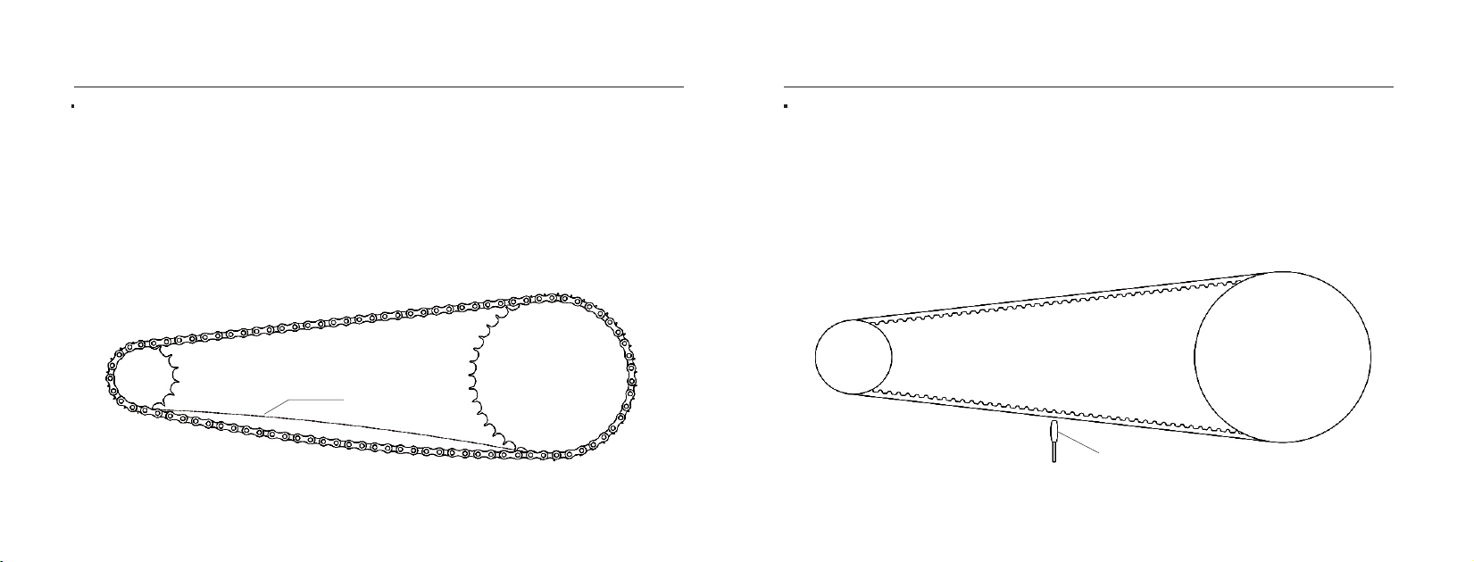
Chain sprockets, chain, and tightness degree
1.Chain sprockets: Rear: 428-46T, Front: 428-15T
2.Chain: GB/T14212 428MH-110
3.Tightness degree:
(1) Measure the chain at the lower end of the middle of the sprocket;
(2) When the tightness is correct, the swing amplitude of the chain at this position is
15-25mm.
Belt Pulley, Belt, and Tightness Degree
1. Belt Pulley:Rear P69-S8M,Front P26-S8M
2. Belt:STD1344-8M
3. Tightness Degree:
(1) Place the belt tension meter probe close to the belt at the lower end of the middle of the pulley;
(2) Use your fingers to move the belt at this part;
(3) Read the value on the tension meter, the correct tightness value is 105~110Hz.
the belt tension meter probe
15-25mm
12 13
Instructions for UseInstructions for Use

Use, Maintenance & Installation of Baery
Body charging
①Locate the charging cover on the right side of the vehicle.
②Insert the charger output plug into the body charging port, and then insert the AC input plug of the charger into the
socket. The indicator light is red during charging, and will turn green after the baery is fully charged. While charging is
done, disconnect from the AC power source right away.
2.External charging
①Use the key to turn right to unlock the baery cover (The keyhole is located at the boom of the seat);
②open the cover to 20º~30º. Lift the upper cover slightly, but do not lift it too high to avoid damage to the components;
③Pull the baery cover forward about 2cm, stretch the upper cover diagonally upward;
④Open the baery cover to the end after extending.
20°~30°
① ②
③ ④
14 15
Instructions for UseInstructions for Use

⑤Turn o the air switch,open the baery strap and pull out the baery cable plug.
baery strap
air switch
baery cable plug
⑥Pull out the baery cable plug to lift the baery, then first insert the charger output plug into the baery charging
port, and then insert the charger AC input plug into the socket. The indicator light is red during charging, and will turn
green after the baery is fully charged. While charging is done, disconnect from the AC power source right away.
⑦To install the baery, just reverse the steps of removing the baery.
⑤
⑥
16 17
Instructions for UseInstructions for Use

Before using the baery, please read the operation instructions carefully. Failure to follow the guidelines may damage
the baery, for instance, baery heats up, catches fire, burst or even more serious consequences.
3. Special aention:Use of Charger
①Protect the baery pack from being sprayed by water or soaked in water;
②Discharging temperature: -20°C–60°C; charging temperature: 0°C-45°C;
③If the vehicle is left unused for long time, please make sure to remove the baery and keep it properly. The baery shall be charged
as it
is used. In addition, the state of long-term storage of the baery is half-saturated (after the baery is fully discharged, charge it with
a charger for 2 to 3 hours). In order to prevent the baery from over-discharging, it is required to charge it every 1 month; the baery
should be stored in dry and well-ventilated places, keep it away from combustible materials. The safe storage duration and tempera-
ture range are as follows:
1 month: -20°C-60°C;
3 months: -20°C-45°C;
1 year: -20°C-25°C;
Leaving the baery stored more than 1 year could damage the power pack and void the warranty.
④The input and output terminals of baery must not being short circuited; the reverse polarity connection of baery positive and
negative terminals on the charger or external device are prohibited;
⑤Don’t throw the baery into fire. Store and keep the baery away from children, fire and heat sources. Don’t smash or drop the
baery, so as to prevent it from being pierced. Don’t disassemble the baery or change its external structure; all these incorrect
behaviors may cause serious damages.
⑥Before charging, please check whether the charger matches the baery model. If the charger has to be replaced, make sure to visit
our distributor or authorized service shop to obtain the approved charger.
⑦If the baery is on fire, please cut o the surrounding power supply promptly and use FE-36 fire extinguisher to extinguish and cool
down the baery. In case the right extinguisher is not available, the water base extinguisher can be applied. However, the dry powder
extinguisher is not applicable for this case.
⑧If there is any question, please contact our distributor or after-sales service department.
1. Before use, check the charger specification firstly. Don’t use the charger with undesignated model.
2. The charger is waterproof grade IP×1. It is strictly prohibited to store and use the charger in rainy or humid outdoor environment.
3. Don’t use the damaged wires for charging.
4. It is strictly prohibited to plug/unplug the charger with wet hands.
5. Don’t use the charger in the place with heat source or under direct sunlight..
6. Don’t use the charger close to combustible materials and explosive gas.
7. It is strictly prohibited to block the air inlet/outlet. The space of at least 10cm shall be left at both inlet and outlet sides.
8. Please check whether the plug at the output end of charger is loose before charging. At the time of charging, plug the charger power
terminal into the indoor power supply first; then connect the output terminal to the charging port of baery pack.
9. The indicator light is red during charging, and will turn green after the baery is fully charged. While charging is done, disconnect from
the AC power source right away.
10. Be sure to unplug the charger when the baery is not being charged or after the completion of charging. First, unplug the output end of
the charger; then the AC power end of the charger.
11. Don’t carry the non-vehicle-mounted charger during riding, so as to prevent the electronic components from becoming loose or being
damaged due to vibration.
12.Please make sure the AC voltage range of AC power supply is consistent with the AC input voltage range of the charger. Please read the
instructions carefully before using. All the damages caused by incorrect use shall be aributed to the man-made improper operation, for
which the manufacturer is not responsible for.
13. Don’t open, repair or disassemble the charger by yourself.
14. It is strictly forbidden to pull the power cord or output cord directly, please use the terminal part to unplug the power cord or output cord.
18 19
Instructions for UseInstructions for Use
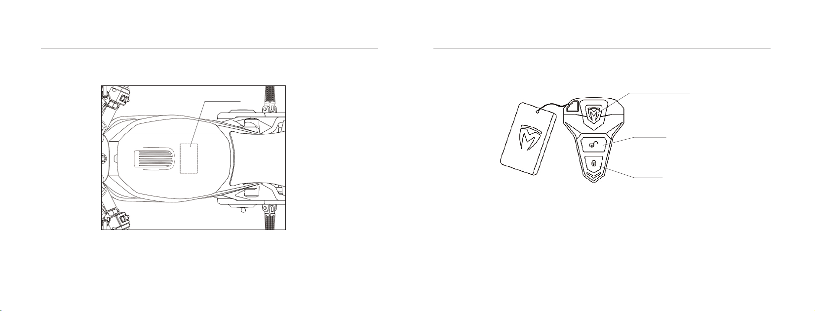
1.NFC Start
①Put the NFC card within 0.3cm of the NFC sensing area to start the vehicle.
②Put the NFC card within 0.3cm of the NFC sensing area to turn o the vehicle.
Locate the Vehicle Buon
Unlock Buon
Lock Buon
NFC
NFC sensing area
Anti-theft Alarm & NFC Start Remote control instructions
2.1 General functions: Locate the Vehicle Function, Anti-theft Seing (power o), Start the Vehicle, Open the Cushion Lock Function;
2.2 Locate the Vehicle Function: Press the locate the vehicle buon twice to find the vehicle, the vehicle will make sounds and the
lights will flash, which enable you to easily check the location of the vehicle.
2.3 Anti-theft Seing: Press the lock buon once, and the vehicle will be powered o and locked (the vehicle will enter the anti-theft
mode in the locked state).
2.4 Start the Vehicle: Press the unlock buon once, and the vehicle can be powered on.
2.5 Open the Cushion Lock Function: Press the locate the vehicle buon once to open the cushion lock.
Note: When the vehicle is not in use, please keep the key at least 5 meters away from the vehicle to prevent meaningless power
consumption.
20 21
Instructions for UseInstructions for Use

UKKO
1. Download and install APP
1.1 Apple IOS
Search “TROMOX UKKO” in APP store to download the APP.
1.2 Android
Search “TROMOX UKKO” in Google Play to download the APP.
2. Registration/Login
2.1 Registration
Enter the registration interface. Then, fill in the mobile phone number, verification code and password to complete the
registration.
2.2 Login
Log in with the account number (the registered mobile phone number) and password.
2.3 Password Forgoen
If you forget the password, please click "Password Forgoen" and fill in the phone number, verification code, and new
password to replace the old one.
2.4 Experience Mode
You can check the function include "vehicle condition"、"Information"、"Message", and "My" at the home page and exit by
clicking My - Seing - Logout. If you want to use more functions, please bind the vehicle first.
Click the arrow to view
the vehicle list and
new added vehicles
The anti-theft alarm
switch can be locked
or unlocked.
Click here to enter the user
and vehicle location map
Remaining mileage (It shows
the test data. Since the riding
environment, speed and load
are dierent, the actual remain-
ing mileage may be dierent
from the data on the display.
Thanks for your understanding!)
TROMOX APP Vehicle condition
The start buon can
be used to turn on or
o the vehicle.
Click the icon
to remotely
lock the vehicle
Click the percentage to
view more details of
baery
22 23
Instructions for UseInstructions for Use
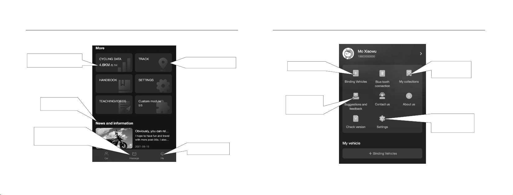
Click to view the vehicle data,
and query the vehicle usage.
Click to view the driving
track, and the riding route.
Click to enter the "My"
menu
Click here to enter the
message management page
and view the vehicle alarm
information.
Click to enter vehicle
binding page
Click to check the
news and events of
your interest
Click here to enter Set
up page, change the
password or phone
number, and log out.
Click to enter the
news page
Click to leave your
comments on our
products and services
24 25
Instructions for UseInstructions for Use
3.1.1 Find the barcode sticker at the end of the manual, enter
the frame code on the sticker or scan the barcode to bind the
vehicle to become the owner.
3.1.2 Scan the “Shared QR Code” (My – Select vehicle – Click
“Vehicle Identification Number”) of vehicle owner to bind the
vehicle. Each user can bind 8 vehicles maximum, each vehicle
can be bound to 5 accounts (including vehicle owner).
3.1.3 Click the vehicle binding management page, in which, the
vehicle unbinding can be done.
a.When the network of mobile phone and vehicle is normal, click the “Anti-theft alarm” switch on the left side to turn on or
o the alarm. Turn on the anti-theft alarm to activate the alarming device; turn o the anti-theft alarm to deactivate the
alarming device.
b. When the network of mobile phone and vehicle is abnormal, after clicking the “anti-theft alarm” switch, the system will
require you to use Bluetooth connection. After the successful connection, user can implement the operation again.
4. Replacement of VCU
Only the vehicle owner can replace the VCU. The replacement procedure is as follows: My – Select vehicle – “VCU version” –
“Scan QR code to replace the VCU equipment”.
Scan the
shared code
Bind vehicle Bind vehicle
Shared
code Unbind Unbind
Vehicle Binding &
Unbinding
app-primary account app-sub account
3.1 Vehicle binding and unbinding
Click “+ Bind vehicle” in the vehicle list:
3. Anti-theft alarm
Pre-ride Inspection:
1.Check whether the head lock is unlocked, and whether the handlebar is flexible without retardation.
2.Check whether the handlebar is firmly fastened, and whether the left and right handlebar switches work normally.
3.Check whether the rearview mirrors are fastened, and in proper angle, whether they are clean enough, and assure the
people and vehicles within the rear 10 meters can be seen clearly.
4.Check whether the tire pressure is within the specified range.
5.Check whether the tire surface has crack or damage, and whether the tread depth is greater than 0.8mm.
6.Ensure that the instrument and mobile phone App have no fault warning after switching on.
7.Check whether the baery is fully charged.
8.Check whether the headlight, tail light and front, rear, left & right turn signal lights work normally.
9.Check whether the horn works normally.
10.Check whether the brake oil is suicient, and whether the brake handle and brake system work normally.
11.If there is any abnormality, please contact our customer service center.
Scan the QR code at
the end of the manual
with your mobile phone
26 27
Instructions for Use Operational Guidance

UKKO
NFC Start:
NFC
NFC sensing area
Click here to turn
on the power.
Vehicle operation Vehicle operation
Starting methods:
TROMOX APP :Remote control:
Click this buon
to unlock the
vehicle
28 29
Operational GuidanceOperational Guidance
Start buon
READY
Preparations before riding:
①Wear your helmet and start journey with Tromox.
②Fold the side stand. Then, the indicator light (P) of side stand on the dashboard will be o. (For VA screen only).
③Press the start buon to unlock the parking status,the indicator light “ready” on the dashboard will be on. At this
moment, the vehicle is ready to drive! (Press the start buon again. Then, the “Ready” indicator light is o and the vehicle
is switched to the parking mode. For TFT screen only.)
* Before riding, please be fully aware the surrounding traic and drive safe.
the
indicator
light (P)
the indicator
light (READY)
30
31
Operational GuidanceOperational Guidance

No. Inspection Interval Inspection Item
01 1 month Check whether the front and rear wheels are fastened.
02 Half a month Check whether the brake calipers are fastened.
03 2 months Check the level of brake oil.
04 3 months Check the lubricating oil level of the gearbox
05 Half a month
Check brake pad status and the braking performance of brake system.
06 1 month Check whether the handlebars are fastened.
07 1 month Check the tightness of the chain/belt.
08 Half a month
09 Half a month
10 1 month Check whether the cable line is worn out or damaged.
11 1 week
12 1 week Check whether the tire pressure is 250kPa.
Regular Self-examination check list
1. Cleaning
①Please make sure to turn o the air switch before cleaning;
②It is strictly prohibited to flush the vehicle directly with strong water stream. Otherwise, the electrical parts may be
damaged or broken down;
③Please clean the vehicle with clear water and neutral detergent. Use soft cloth to dry the vehicle after washing to prevent
scratching; It is strictly forbidden to use sandpaper and metal brushes to clean the vehicle;
④If the electrical system is accidentally aected during cleaning, please dry it with electrical dryer.
Check the lubrication condition of the chain (make sure to
cut o the power before lubricating and chain inspection).
Check the belt cleanliness (make sure to cut othe power
before cleaning and checking the belt)
Check whether the vehicle has abnormal sound
or the sound caused by loose parts.
Regular maintenance can improve the safety of the vehicle, as well as the service life. Please go to the authorized distribu-
tor or service provider for regular maintenance and inspection of the vehicle according to the following suggestions.
32 33
MaintenanceMaintenance

3. Long-term Storage
①Storage status: turn o the air switch; disconnect the power supply circuit of baery, so as to prevent the over-discharge
of the baery;
②Storage conditions: park the vehicle at dry and cool places, so as to protect it from being exposed to the strong sun light
and rain. If the outdoor parking cannot be avoided, make sure to take out the baery, cover the vehicle with waterproof
cover and mind the wind conditions.
③In case long storage of the vehicle, please charge the baery fully before using, and check whether the tire pressure
reaches the specified value. If the tire pressure is too low or too high, please restore the tire pressure to the specified value
before using.
4. Maintenance Precautions
①The maintenance and repairing of parts and components needs to be performed by our after-sales service center,
authorized service shops or distributors. Only the parts and components designated by the original factory can be used.
②The fault or part damage caused by the owner that fails to perform the regular maintenance according to Tromox’sugges-
tions is not within the warranty scope;
③Tromox can not be responsible for the results if the owner disassembles vehicle by himself/herself or uses the parts
which are not oicially approved by Tromox.
Baery connection failed Connect the baery plug correctly.
Anti-theft alarm fault
Fuse burned
Air switch is not on
Side stand is not folded
Baery is low
Handlebar fault
Controller plug loose
Handlebar plug subjected to
poor contact
Motor Hall plug subjected to poor
contact
Motor failure
Controller failure
Baery is low
Tire pressure insuicient
Seriously overloaded
Brake pad interfering
Baery aged or normally
scrapped
Power inverter failure
Brake handle switch damaged or
subjected to open circuit
The main charging plug
subjected to poor contact
Wrong charger
Baery aging or normal
scrap
Brake pad is worn out
Brake disc loose
Control switch failure
Plug loose or not inserted
Power inverter failure
Lamp holder burnt out
Power inverter failure
Control switch failure
Flasher failure
Lamp holder is burnt out
dashboard failure
Power inverter failure
VCU communication module
failure
Anti-theft alarm communica-
tion module failure
Controller communication
module failure
Instrument communication
module failure
Check whether the main plug is
correctly inserted.
Use the Tromox charger with
designated model.
Replace the baery.
Replace the brake pad.
Tighten the bolts of brake disc.
Replace the switch.
Check the plug.
Replace the power inverter.
Replace the lamp.
Replace the power inverter.
Replace the switch.
Replace the flasher.
Replace the lamp.
Replace the dashboard.
Replace the power inverter.
Replace the VCU.
Replace the Anti-theft alarm
Overhaul the controller
communication module.
Overhaul the instrument
communication module.
Replace the anti-theft alarm.
Replace the main cable fuse.
Turn on the air switch.
Fold the side stand.
Charge the baery.
Lubricate the brake handle joint and
turn it to the correct position.
Replace the handlebar.
Re-insert the controller plug.
Adjust the handlebar plug pins.
Adjust the motor Hall plug pins.
Overhaul or replace the motor.
Replace the controller
Charge the baery.
Remain the tire pressure at
225kPa.
Avoid overloading
Overhaul the brake caliper and
adjust its installation position.
Replace the baery
Replace the power inverter
Replace the switch and inspect
the circuit
Causes CausesSolutions SolutionsFaults Faults
The whole
vehicle is
powered o;
the remote
control and
APP cannot
be on.
The baery
cannot be
charged.
There is metal
scraping
sound while
braking
The headlight
and tail light
cannot be
switched on.
The turn
signal light
doesn’t work.
The vehicle can
be turned on, but
the dashboard
light is not on.
There is no baery
level, speed, time,
temperature or
other information
displayed on the
dashboard.
The motor
doesn’t run
when the
power is on,
and the
governor
handlebar is
turned.
The riding
speed is low
or the riding
range is
relatively
short
The brake failure
Baery management system(BMS)
subjected to power-o protection
First, ensure there is no short
circuit; after 10 minutes, turn on
the power again
Brake handle is not back to
the correct position
34 35
TroubleshootingMaintenance

The user should correctly operate and use the vehicle according to the Owner’s Manual. If a functional failure occurs due to
product quality reasons, TROMOX will perform an unified repair, replacement, and return policy.
1.The Tromox after-sales service and limited warranty are implemented by distributors or authorized service shops. If there
is any problem, please contact the after-sales service department or authorized distributors.
2.The list of after-sales service and limited warranty is as follows.
After-sales Service and Limited Warranty
Part Name
Power pack
Motor
Converter
Remote key
Vehicle control
unit (VCU)
Main cable
Headlight
Taillight
Turn signal light
License plate light
Controller
Warranty Standard
Warranty Period
After being charged fully under the specified service environment and used normally without the influence of external force, the
lithium baery subjected to voltage abnormal, unable to be charged,temperature abnormal, or capacity less than 70% (the
normal charging environment temperature is 0ª~55ª; the normal service environment temperature is -20ª~70ª; under the
low-temperature condition, the capacity of lithium baery will decrease at dierent extent) is provided with a unified repair,
replacement, and return policy. (The warranty period of the new lithium baery is calculated according to the remaining days of
the warranty period of original purchased baery.)
3+21 months: provide
the replacement
service in the first 3
months and the repair
or maintenance service
in the laer 21 months.
Subjected to phase loss, demagnetization, parts or debris falling o, abnormal sound and other quality problems
which cannot be repaired
Subjected to internal damage, no voltage regulation, no DC output and supply voltage too high
No DC output & supply voltage abnormal
The internal line or element is damaged, dashboard provides no data or incorrect data and the vehicle cannot be
controlled through mobile phone App.
a. The conventional functions of the remote control such as unlocking, fortifying, powering on, and powering o are
invalid
Be subjected to short circuit, open circuit, ablating or other irreparable faults
Cannot work normally due to quality problem
Cannot work normally due to quality problem
Cannot work normally due to quality problem
Cannot work normally due to quality problem
24 months
12 months
12 months
12 months
12 months
12 months
12 months
12 months
12 months
12 months
Part Name
Charger
Horn
Lock
Dashboard
Brake system
Handle
Switch Assy
Air switch
Handlebar
Steering column
Shock absorber
Wheel rim
Tire
Vehicle frame
Side stand
Seat cushion
Vehicle appearance
& plastic parts
Rear fork
Warranty Standard
Warranty Period
Cannot be charged normally; charging indicator light doesn’t change
Cannot work normally due to quality problem
Out of order, subjected to functional failure
Incomplete display, no display or abnormal display
a.The brake caliper is broken or seriously deformed;
b.The brake oil leaks and cannot be repaired;
c.Power is not o during brake and cannot be repaired.
The speed cannot be adjusted due to structure problem
The switch is out of order, cannot be turned on or o to the proper position or cannot be reset; the part is broken or falls o due to
quality problem; the internal part is subjected to short circuit, open circuit, poor contact or other failures.
It doesn’t automatically disconnect for protection in case of over-voltage or over-current, or cannot be normally used.
Handlebars at two sides have uneven height and inconsistent length and exceed the normal range; or, subjected to serious deforma-
tion, fracture or crack during normal operation.
Subjected to serious deformation, insuicient welding, fracture or crack during normal operation
Subjected to fracture, crack, serious deformation or insuicient welding
Subjected to oil leakage, insuicient welding, piston rod fractured or piston stuck during normal operation
Subjected to fracture, crack or serious deformation during normal operation
Subjected to crack, bulge or breakage during normal operation
Subjected to serious deformation, insuicient welding, or cracking during normal operation; the license plate cannot be obtained due
to the Frame code is not clear
Subjected to fracture, insuicient welding, spring failure or falling o during normal operation
Subjected to split sewing, cracking or serious deformation due to quality problem
Surface subjected to peeling o due to coating problem; the parts can be replaced if the cracking area is bigger than 1cm².
24 months
6 months
6 months
12 months
6 months
6 months
6 months
6 months
12 months
12 months
12 months
12 months
12 months
1 months
36 months
36 months
6 months
3 months
36 37
After-sales ServicesAfter-sales Services
This manual suits for next models
2
Table of contents


