Trox TAP Series User manual

TROX AIR PURIFIERS
TAP-L TAP-M
Operating instructions
Read the instructions prior to performing any task!
GB/en

A00000083746, 4, GB/en
© 2020
TROX GmbH
Heinrich-Trox-Platz
47504 Neukirchen-Vluyn, Germany
Germany
Phone: +49 (0) 2845 2020
Telefax: +49 2845 202-265
E-mail: [email protected]
Internet: http://www.troxtechnik.com
11/2020
TROX AIR PURIFIERS TAP-L TAP-M2

About this manual
This operating manual enables the TROX air purifier
TAP to be used safely and efficiently.
Read this manual carefully before commissioning/using
the unit, and always keep it in the immediate vicinity of
the installation site or on the unit!
Read all safety notes and instructions and follow them
carefully. Non-compliance with the safety instructions
and warnings can result in an electric shock, fire and/or
serious injury. Keep the manual and safety instructions
for future reference.
Illustrations in this operating manual are mainly for infor-
mation and may differ from the actual design of the air
purifier unit.
TROX Technical Service
To ensure that your request is processed as quickly as
possible, please keep the following information ready:
Product name
TROX order number
Delivery date
Brief description of the fault
Online www.troxtechnik.com
Phone +49 2845 202-400
Copyright
This document, including all illustrations, is protected by
copyright and pertains only to the corresponding
product.
Any use without our consent may be an infringement of
copyright, and the violator will be held liable for any
damage.
This applies in particular to:
Publishing content
Copying content
Translating content
Microcopying content
Saving content to electronic systems and editing it
Limitation of liability
The information in this manual has been compiled with
reference to the applicable standards and guidelines,
the state of the art, and our expertise and experience of
many years.
The manufacturer does not accept any liability for dam-
ages resulting from:
Non-compliance with this manual
Incorrect use
Operation or handling by untrained individuals
Unauthorised modifications
Technical changes
Use of non-approved replacement parts
The actual scope of delivery may differ from the infor-
mation in this manual for bespoke constructions, addi-
tional order options or as a result of recent technical
changes.
The obligations agreed in the order, the general terms
and conditions, the manufacturer's terms of delivery,
and the legal regulations in effect at the time the con-
tract is signed shall apply.
We reserve the right to make technical changes.
Warranty claims
The provisions of the respective delivery terms apply to
warranty claims. For purchase orders placed with TROX
GmbH, these are the regulations in section "Vl. War-
ranty claims" of the Delivery and Payment Terms of
TROX GmbH, see www.trox.de/en/ .
Supplemental instructions
TROX AIR PURIFIERS TAP-L TAP-M 3

Safety notes
Symbols are used in this manual to alert readers to
areas of potential hazard. Signal words express the
degree of the hazard.
Comply with all safety instructions and proceed carefully
to avoid accidents, injuries and damage to property.
DANGER!
Imminently hazardous situation which, if not avoided,
will result in death or serious injury.
WARNING!
Potentially hazardous situation which, if not avoided,
may result in death or serious injury.
CAUTION!
Potentially hazardous situation which, if not avoided,
may result in minor or moderate injury.
NOTICE!
Potentially hazardous situation which, if not avoided,
may result in property damage.
ENVIRONMENT!
Environmental pollution hazard.
Tips and recommendations
Useful tips and recommendations as well as informa-
tion for efficient and fault-free operation.
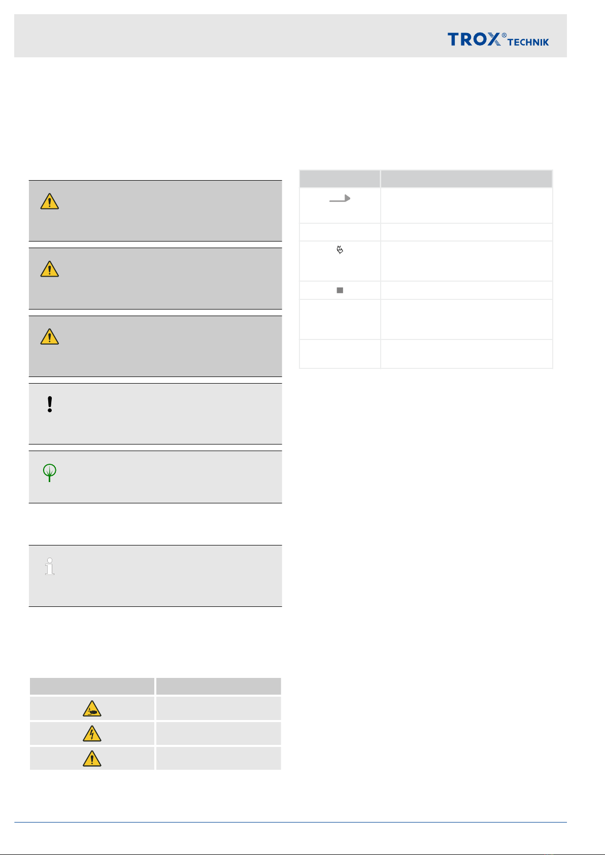
Specific safety notes
The following symbols are used in safety notes to alert
you to specific hazards:
Warning signs Type of danger
Warning – hand injuries.
Warning – high-voltage.
Warning – danger zone.
Additional markers
In order to highlight instructions, results, lists, refer-
ences and other elements, the following markers are
used in this manual:
Marker Explanation
1., 2., 3. ...
Step-by-step instructions
ðResults of actions
References to sections in this
manual and to other applicable
documents
Lists without a defined sequence
[Switch] Operating elements (e.g. push but-
tons, switches), display elements
(e.g. LEDs)
‘Display’ Screen elements (e.g. buttons or
menus)
Supplemental instructions
TROX AIR PURIFIERS TAP-L TAP-M4

1 Safety ................................................................ 6
1.1 Correct use ................................................ 6
1.2 Qualified staff ............................................. 7
1.3 Personal protective equipment .................. 7
1.4 Signs on the unit ........................................ 7
1.5 Residual risks ............................................ 8
1.6 Behaviour in an emergency ....................... 9
2 Information about the unit ............................ 10
3 Transport, storage and packaging ............... 12
3.1 Supply package ....................................... 12
3.2 Transport to the installation location ........ 12
3.3 Storage .................................................... 13
3.4 Packaging ................................................ 13
4 Installation ...................................................... 14
4.1 Dimensions and space required .............. 14
4.2 Mounting .................................................. 15
4.3 Mains connection .................................... 15
5 Operation ........................................................ 16
5.1 Control elements and status LEDs .......... 16
5.2 Switching on ............................................ 16
5.3 Operation ................................................. 16
5.4 Switching the unit off ............................... 16
5.5 Operation on a timer ................................ 17
5.6 Adjustment of the volume flow rate ......... 17
6 Troubleshooting ............................................ 18
7 Maintenance and cleaning ............................ 19
7.1 Check and change filter ........................... 19
7.2 Cleaning and disinfection ........................ 20
8 Technical data ................................................ 21
8.1 Circuit diagram ........................................ 22
9 Disposal .......................................................... 23
10 Declaration of conformity ............................. 24
11 Commissioning report/Maintenance report
.......................................................................... 25
12 Index................................................................ 26
Table of contents
TROX AIR PURIFIERS TAP-L TAP-M 5

1 Safety
WARNING!
– Place the unit upright so it is stable and on a sur-
face with sufficient load capacity. Secure the unit
to a wall using the supplied fixing bracket.
– Make sure that all electrical cables outside the
unit are protected against damage (e.g. from ani-
mals).
– Before each use, check the unit and connection
parts for possible damage. Do not use defective
units or parts of units.
– Never use the unit if you discover any damage to
the mains plug, mains cable or mains connec-
tion. Defective mains cables are a serious injury
risk!
If the mains cable of this unit is damaged, a new
one must be installed by the manufacturer, its
customer service or a specialist company in
order to avoid hazards.
– Insert the mains plug into a correctly fused mains
socket. Lay the mains cable so that no one can
step on the mains cable and there is no risk of
tripping.
– Select extensions for the mains cable taking into
account the technical data. Fully unroll the exten-
sion cable. Avoid electrical overload.
– The power connection must comply with the
specifications in the Technical data chapter.
– Do not cover the unit during operation and do not
place objects such as clothes on the unit.
– Make sure that the air inlet and air outlet are
clear.
– Make sure that there are never any loose objects
and dirt in the immediate vicinity of the air inlet
and outlet.
– Never insert limbs or objects into the unit.
– After wet cleaning, allow the unit to dry. Do not
operate it when wet.
– Do not operate or handle the unit with wet or
damp hands.
– Do not expose the unit to a direct stream of
water.
– The unit is not a toy. Keep children and animals
away. Use the unit only under supervision.
– Do not use the unit to suck in vapours or liquids.
– Switch off the unit and unplug the mains cable
from the mains socket when you are not using
the unit.
– Before maintenance, cleaning or repair work,
remove the mains plug from the mains socket.
Always unplug the mains cable by holding the
plug (never by the cable).
– During installation, observe the minimum dis-
tances from walls and objects and the operating
conditions.
– Do not remove any safety signs, stickers or
labels from the unit. Keep all safety signs,
stickers and labels in a legible condition.
– Dispose of replaced filters properly, especially
after filtering out harmful substances (e.g.
asbestos or paint mist).
1.1 Correct use
The TROX air purifier is used to purify atmospheric air
indoors. As a stationary air purifier, the unit ensures a
relevant reduction in dust and aerosol concentration in
the indoor air. By using a HEPA filter H13, it filters
99.95% of all aerosols out of the air and thus effectively
reduces the infection risks.
The unit is used for purifying the indoor air in heavily fre-
quented rooms, such as:
Waiting and reception areas
Meeting or conference rooms
Schools
Trade fair booths
Dining rooms
Shops
Incorrect use
WARNING!
Danger due to incorrect use!
Misuse of the unit can lead to dangerous situations.
Any use other than that specified in this manual is
prohibited. In case of non-observance, any liability
and the right to claim under warranty expires.
Incorrect use includes:
– Any use that is not described in the manual.
– Operation that does not comply with the tech-
nical data.
– Modifying of the unit by others, tampering with
the unit.
– Operation or installation in areas with potentially
explosive atmospheres.
– Operation in rooms where the indoor air contains
particles that are conductive, aggressive, corro-
sive, combustible or hazardous to health
– Operation in rooms where the humidity is perma-
nently high (> 90 %)
– Operation outdoors
– Use of the air purifier for forced ventilation
– Operation without air filters
– Use of non-genuine replacement parts or acces-
sories, whose quality and function are not equiv-
alent to those of the original parts
Safety
Correct use
TROX AIR PURIFIERS TAP-L TAP-M6

1.2 Qualified staff
Instructed person
The instructed person has been instructed by the
system owner with regard to the tasks delegated to
them and potential hazards in the event of inappropriate
behaviour.
The instructed person is allowed to carry out the fol-
lowing activities on the unit:
Carry out visual checks.
Change filter.
Clean unit casing and filter chambers.
1.3 Personal protective equipment
Personal protective equipment is equipment that pro-
tects the user against health or safety risks at work.
Personal protective equipment must be worn for various
types of work; the protective equipment required is
listed in this manual together with the description of
each type of work.
Description of personal protective equipment
Disposable gloves
Disposable gloves are used to protect the hands from
contamination and from contact with contaminated
material.
Dust mask FFP2
Dust masks protect users from inhaling contaminated
material such as aerosols and harmful dusts.
Safety shoes
Safety shoes protect the feet against crushing, falling
parts, and from slipping on slippery ground.
1.4 Signs on the unit
The following symbols and information signs are found
on the air purifier. They apply to the very location where
they are found.
WARNING!
Danger due to illegible signage!
There is a risk of injury if hazards and operating
instructions cannot be identified.
– Ensure that all of the safety, warning and oper-
ating information is clearly legible.
– Replace illegible signs or stickers immediately.
Dangerous electrical voltage
This sign refers to hazardous electrical voltage. The
protective cover of the electrical connections is only
allowed to be opened by a qualified electrician. The
mains plug must be removed before opening. The
stickers are located on the outside, on the back of the
unit at the mains isolator and on the inside of the cover
of the electrical connections.
Safety
Signs on the unit
TROX AIR PURIFIERS TAP-L TAP-M 7

Injuries on the fan impeller
Fig. 1
This sticker indicates the danger of the rotating fan. It is
located on the fan cover.
Comply with the manual
Fig. 2: Comply with the manual
This sticker indicates that the operating manual must be
read and understood before any work is performed on
the air purifier. It is located inside the unit, behind the
door and above the filters.
1.5 Residual risks
Electric current
DANGER!
Danger of death due to electric current!
Danger of electric shock! Do not touch any live com-
ponents! Damaged insulation or damaged parts are
a life threatening hazard.
– Only skilled qualified electricians must work on
the electrical systems.
– If the insulation is damaged, disconnect the
power supply immediately and have the insula-
tion repaired.
– Before you start maintenance or cleaning, pull
the mains plug.
– Ensure that live parts do not come into contact
with moisture. Moisture can cause a short circuit.
Rotating parts
WARNING!
Risk of injury from rotating parts!
Rotating parts in the fan can cause serious injuries.
– Before you start maintenance or cleaning, pull
the mains plug.
– Do not reach into the moving fan.
– The fan does not stop immediately! Check that
no parts are moving once you have opened the
casing cover.
– Do not open the casing cover while the fan is in
operation.
Stability
WARNING!
Risk of injury due to loss of stability!
Serious injuries can be caused if the unit falls over.
– When the unit is stationary, during transport (e.g.
trolley) the unit must be transported by at least 3
persons.
– Be careful when transporting the unit.
– After setting up the unit, secure it with the sup-
plied fixing bracket to prevent it from tipping over.
Safety
Residual risks
TROX AIR PURIFIERS TAP-L TAP-M8

Damaged fan parts
WARNING!
Risk of fire from damaged fan parts!
Grinding rotors or overheating bearings can cause a
fire and eventually serious or even fatal injuries.
– Do not put a damaged or defective fan into oper-
ation.
– If you hear running noises, switch off the unit and
have it repaired.
Hygiene issues
CAUTION!
Health risk due to hygiene issues!
If you do not adhere to the maintenance intervals or
if the unit is not used for a relatively long time (sev-
eral weeks), bacteria and germs may start growing in
the air filter.
– Comply with the maintenance intervals for filter
changes.
– Change the air filters if the unit has been stopped
for a long period of time.
Children and persons with impaired perception
WARNING!
Children and persons with impaired perception
Handling the air purifier can lead to dangerous situa-
tions for children and persons with impaired percep-
tion.
– The air purifier must not be operated by children
and persons with reduced physical, sensory or
mental abilities, or lack of experience or knowl-
edge.
– Children are not allowed to play with the air puri-
fier.
– Packaging materials must not be used for
playing. There is a risk of suffocation.
– Maintenance and cleaning work must not be car-
ried out by children.
1.6 Behaviour in an emergency
1. Switch the unit off
2. In an emergency, disconnect the unit from the
mains supply. Remove the mains plug from the
mains socket.
ðDo not reconnect a defective unit to the mains
supply. Have the unit repaired by the manufac-
turer or a qualified specialist company.
Safety
Behaviour in an emergency
TROX AIR PURIFIERS TAP-L TAP-M 9

2 Information about the unit
Overview of the unit
Fig. 3: TAP-L
1 Air discharge
2 Fixing bracket
3 Casing
4 Door
5 Flush pull handle
6 Door lock, operated with hexagon key size 10
7 Cover cap hexagon socket
8 Air inlet
9 Fan sound attenuator unit
10 Controller
11 Main filter HEPA-H13
12 Prefilter
13 Filter change alert (red)
14 Mains isolator with indicator light (green)
15 Mains connection cable
16 Micro fuse on electrical connection box (behind
main filter)
Construction variants
The air purifier is supplied in two construction variants
(L and M), which differ in size (unit depth), weight,
volume flow rate, sound power and filter size,
Ä
8
‘Technical data’ on page 21 .
Functional description
Information about the unit
TROX AIR PURIFIERS TAP-L TAP-M10

Fig. 4: Airflow
The TROX air purifier draws indoor air into the unit at
the lower air intake and feeds it to the filters. The pre-
filter separates coarser particles, then the HEPA filter
separates the smallest suspended particles from the
indoor air. A fan conveys the airflow through the unit
and returns the filtered air to the room via the upper
outlet. The sound attenuators placed in front and behind
the fan reduce the operating noise to a pleasant min-
imum.
With its operation, the TROX air purifier ensures a sig-
nificant reduction in particles and aerosol concentration
in rooms.
The effective filtering in conjunction with a high volume
flow rate (airflow rate) enables the air purifier to consid-
erably reduce the amount of germs, viruses and bac-
teria (depending on the room size) and thus also cut the
risk of infection.
Information about the unit
TROX AIR PURIFIERS TAP-L TAP-M 11

3 Transport, storage and
packaging
3.1 Supply package
Check the packages on arrival for transport damage
and completeness. If necessary, carefully remove and
then replace the packaging.
Supply package:
TROX air purifier
Fixing bracket
Prefilter and HEPA H13 filter (inserted in the unit)
Operating manual
Transport damage
If there is any visible damage, proceed as follows:
Either do not accept the delivered items, or accept
them with reservations.
Note down the damage on the shipping documents
or on the shipping company's delivery note.
File a complaint.
File a complaint as soon as you detect any damage.
Claims for damages can only be filed within the
applicable complaint periods.
3.2 Transport to the installation loca-
tion
Protective equipment:
Safety shoes
WARNING!
Risk of injury due to loss of stability!
When the unit is upright, the high centre of gravity
and small footprint represent a high risk of tipping
over during unloading, transport and installation.
Be sure to take adequate precautions:
– If possible, transport the unit lying on the pallet to
the installation site.
– When the unit is upright, use additional means to
prevent it from tipping over (e.g. lashing with
ratchet straps).
– Use only lifting and transport gear designed for
the required load.
– When setting the unit upright, secure it against
shifting and tipping over until installation is com-
plete.
If possible, do not remove the unit from the pallet
until you reach the installation site.
Use a pry bar and pincers to unpack the unit from
the pallet.
If the unit is transported without a pallet, the foil
packaging must remain on the unit until it is installed
on site to protect against damage to the paintwork.
Fig. 5: Transport with pallet truck or forklift
Fig. 6: Setup:
1. Lifting
2. Move to the edge of the pallet
3. Set upright carefully on the floor
Fig. 7: Transport by trolley
Transport, storage and packaging
Transport to the installation location
TROX AIR PURIFIERS TAP-L TAP-M12

3.3 Storage
Please note:
Do not store outdoors.
Store away from direct sunlight.
Protect the unit from humidity, dust and contamina-
tion.
Storage temperature: -10 °C to 50 °C.
Relative humidity: 95% max., no condensation.
Store the unit only in its original packaging.
If the unit is stored upright, its stability must be
ensured.
If a unit has to be stored for more than 3 months,
regularly check the general condition of all parts and
of the packaging.
3.4 Packaging
Packaging materials:
Wood
Cardboard
Foil packaging
Expanded polystyrene
ENVIRONMENT!
Handling packaging materials
Properly dispose of packaging material!
Transport, storage and packaging
Packaging
TROX AIR PURIFIERS TAP-L TAP-M 13

4 Installation
4.1 Dimensions and space required
Dimensions
Fig. 8: Unit dimensions TAP-L and TAP-M
①Door opening dimension (hinge left)
②Fixing bracket (wall distance)
Space required
Fig. 9: Setup: against a wall or in a corner
Distance from ceiling (d) at least 100 – 200 mm
Distance from side wall (w) 1 – 3 m
T TAP-L: 851; TAP-M: 591 mm
The distances depend on the volume flow rate set on the air purifier.
With regard to space requirements, it must be ensured that the control elements on the rear of the unit remain
accessible and that the door can be opened far enough to allow a filter change (door opening angle 90°).
Installation
Dimensions and space required
TROX AIR PURIFIERS TAP-L TAP-M14

4.2 Mounting
WARNING!
Risk of injury due to loss of stability!
The high centre of gravity and small footprint repre-
sent a high risk of the unit tipping over.
Immediately after the unit has been set upright, it
must be secured to a wall using the supplied fixing
bracket.
Fig. 10: Securing of the fixing bracket on the wall
Secure the bracket to the wall with suitable fixing mate-
rial (screws and wallplugs) (slotted holes 7 mm).
Fig. 11
Push the unit up to the bracket and secure the unit to
the bracket, to prevent it from falling over, with the hex-
agon screws (M6x20) supplied.
4.3 Mains connection
To connect the unit to the mains, insert the mains plug
of the unit into a mains socket.
The mains plug serves as a disconnecting device to dis-
connect the unit from the power supply. It is therefore
necessary that the mains socket is close to the unit and
easily accessible.
Installation
Mains connection
TROX AIR PURIFIERS TAP-L TAP-M 15

5 Operation
5.1 Control elements and status LEDs
Fig. 12: Status LEDs
1 Mains isolator
2 Filter change alert
3 Controller
Mains isolator (green)
The mains isolator is used for switching the unit on or off
Status LED:
Off - Unit is switched off or there is no
supply voltage.
Permanent
light, green
- Unit is switched on, supply voltage is
applied.
Filter change alert (red)
Off - Unit is working properly.
Lights up red - Filter dirty, filter must be changed.
Controller display
Display Description
qv [m³/h] Volume flow rate actual
value
Setpoint 1 [m³/h] Volume flow rate setpoint
value
Range qv [m³/h] Maximum controllable
volume flow rate
Vout [V] Actual value of the output
voltage
Δ[Pa] Actual value of the differ-
ential pressure
Time not used
UNICON CPGxxx-AVC Software version
It is possible to scroll through the display using the ▼ /
▲ keys
5.2 Switching on
Prerequisites:
Filters must be inserted and in proper condition.
Door closed.
Air inlet and air outlet must be free.
1. Plug in mains plug.
2. Switch the unit on at the mains isolator
( Fig. 12 /1).
ðAfter switching on (if mains voltage is applied
to the unit), the green indicator lamp on the
mains isolator lights up.
When the unit is switched on, the fan speed is
slowly increased (starting time 2-3 min). The
unit is hardly audible, due to the very good
sound insulation properties.
5.3 Operation
The door must remain closed during operation, other-
wise the indoor air flowing in through the door will not be
filtered.
The fan can also pulsate when the door is open. As
soon as the door is closed, the fan runs properly again.
5.4 Switching the unit off
Use the mains isolator to switch off the unit
( Fig. 12 /1).
ðIf necessary, pull out the mains plug, e.g.
during maintenance work or longer interrup-
tions in operation.
Operation
Switching the unit off
TROX AIR PURIFIERS TAP-L TAP-M16

5.5 Operation on a timer
The unit can be operated on a timer, but the power con-
sumption of the unit must be taken into account,
Ä
Chapter 8 ‘Technical data’ on page 21 . The set-
tings of the unit are retained even when the supply
voltage is disconnected. The daily checks on the appli-
ance must be carried out.
5.6 Adjustment of the volume flow rate
The volume flow rate is programmed in the factory to
the specified room size. If it is necessary to adjust the
volume flow rate, this can be set on the controller in the
‘Setpoint 1’ menu item as described below.
In addition, the limit value for the filter change must be
set to the changed volume flow rate, ‘Level Max.’ menu
item.
Pulsation of the fan
The fan can pulsate when the door is open. As soon
as the door is closed, the fan runs properly again.
Fig. 13: TAP controller
Display
500 m³/h - 1st line = Actual values and set-
point values
Setpoint 1 - 2nd line = Menu item
Function of keys
P - Programming key and open menu
▼ - Menu selection, reduce value
▲ - Menu selection, increase value
▼ + ▲ - Esc key combination,
Escape = Exit menu
Setting the volume flow rate
1. Press the [▼] [▲] keys at the same time until
‘INFO’ appears.
2. Press the [▼] key until ‘SETTING’ appears.
3. Press the [P] key
ðSetpoint 1 appears
4. Press the [P] key again to activate setting mode.
ðSetting value flashes
5. Use the [▼] or [▲] key to set the desired value
[m³/h], setting range TAP-L: 400...1600 m³/h, TAP-
M: 200...1200 m³/h.
6. Press the [P] key to accept the value.
Setting the limit for filter change
7. Press the [▼] [▲] keys at the same time.
ð‘SETTING’ appears
8. Press the [▼] key until ‘LIMITS’ appears.
9. Press the [P] key
ð‘Level Function’ appears
10. Press the [▼] key until ‘Level Max.’ appears.
11. Press the [P] key to activate setting mode.
ðSetting value flashes
12. Set the value using the [▼] or [▲] key according
to the table. Intermediate values can be interpo-
lated.
Volume flow
rate [m³/h]
Level max. [V]
TAP -L TAP-M
200 – 4.1
400 4.1 5.3
600 4.9 6.5
800 5.8 7.7
1000 6.7 9.0
1200 7.6 10.0
1400 8.4 –
1600 9.3 –
13. Press the [P] key to accept the value.
14. Press the [▼] [▲] keys at the same time.
ð‘Limits’ appears
15. Press the [▼] key until ‘Info’ appears.
16. Press the [P] key to exit the settings menu.
ðVolume flow rate and limit value for filter
change set to new values.
Operation
Adjustment of the volume flow rate
TROX AIR PURIFIERS TAP-L TAP-M 17

6 Troubleshooting
DANGER!
Danger of death due to electric current!
Danger of electric shock! Do not touch any live components!
– Only skilled qualified electricians must work on the electrical systems.
– Switch off the power supply before you carry out maintenance or cleaning.
– Ensure that live parts do not come into contact with moisture. Moisture can cause a short circuit.
WARNING!
Risk of injury from rotating parts!
Rotating parts in the fan can cause serious injuries.
– Do not reach into the moving fan or tamper with it.
– Never open covers while the unit is in operation.
– Make sure that the rotor is inaccessible while in operation.
– Before opening the door, switch off the unit and pull out the mains plug, wait for the run down time.
The unit has been produced carefully and tested for perfect function. Should malfunctions nevertheless occur, the
fault can be rectified if necessary with reference to the following list:
Fault description Cause Remedy
Unit (fan) does not run Unit is not switched
on.
Switch the unit on at the mains isolator,
Ä
Chapter 5.2
‘Switching on’ on page 16 .
No voltage. Check mains fuse
Check 3.15 A micro fuse (at the electrical connection box
(behind the main filter))
Disconnect main plug and check plug and connecting cable
Check supply voltage
Unit output too high, e.g.
draught
Volume flow rate too
high
Reduce volume flow rate
Ä
Chapter 5.6 ‘Adjustment of the
volume flow rate’ on page 17
Unit output too low Volume flow rate too
low
Increase volume flow rate
Ä
Chapter 5.6 ‘Adjustment of the
volume flow rate’ on page 17
Red indicator light on Air filter contaminated Check air filter for contamination, renew if necessary,
Ä
Chapter 7.1 ‘Check and change filter’ on page 19
Test run without filter
Controller or fan
faulty
Switch off unit and notify customer service
Unit is loud or vibrates Door open Close door
Filter is dirty Check air filter for contamination, renew if necessary,
Ä
Chapter 7.1 ‘Check and change filter’ on page 19
Test run without filter
Fan or bearing defec-
tive
Switch off unit and notify customer service
If you are unable to rectify the fault yourself:
Contact the TROX customer service (see page 3) or a qualified electrician.
Troubleshooting
TROX AIR PURIFIERS TAP-L TAP-M18

7 Maintenance and cleaning
Maintenance measures
Job Interval
daily as required 4 weeks 6 months 1 year 2 years
Check air inlet and outlet for for-
eign matter and contamination,
clean if necessary
X
Cleaning the outside of the
casing
X X
Check the inside of the casing
for contamination, clean if nec-
essary
X X
Check fixing screws X
Replace HEPA filter X X
Replace prefilter X X
Test run X
7.1 Check and change filter
Personnel:
Instructed person
Protective equipment:
Disposable gloves
Dust mask FFP2
Special tool:
Allen key size 10
We recommend only carrying out a filter change outside
the period of use to avoid the risk of infection for other
people.
1. Switch the unit off,
Ä
Chapter 5.4 ‘Switching the
unit off’ on page 16
2.
Disconnect the mains plug!
Remove the mains plug from the socket.
3. Open the door by removing the cover cap on the
lock and opening the door lock with a size 10 hex-
agon socket key.
Checking prefilter
4. Pull out the prefilter (lower filter).
Check the filter for damage, contamination,
moisture and odours.
Check the filter chambers for contamination
and clean them with a damp cloth if neces-
sary.
ðReplace the prefilter if required, or according
to the specified change intervals.
Changing prefilter
5. Pull the contaminated filter out of the air purifier,
put it into a plastic bag and dispose of it properly,
see notes on disposal
Ä
‘Disposal ’
on page 20 .
6. Do not touch or damage the filter packs when
inserting the new filters. Only hold the filter by the
frame to avoid damage to the filter.
Checking HEPA filter
7. Pull out the HEPA filter (upper filter).
Check the filter for damage, contamination,
moisture and odours.
Check the filter chambers for contamination
and clean them with a damp cloth if neces-
sary.
ðReplace the filter if required, or according to
the specified change intervals.
Changing HEPA filter
8. Pull the contaminated filter out of the air purifier,
put it into a plastic bag and dispose of it properly,
see notes on disposal
Ä
‘Disposal ’
on page 20 .
9. Do not touch or damage the filter packs when
inserting the new filters. Only hold the filter by the
frame to avoid damage to the filter.
10. Close the door and put the cover cap back on the
door lock. Switch the unit on again,
Ä
Chapter
5.2 ‘Switching on’ on page 16 .
Maintenance and cleaning
Check and change filter
TROX AIR PURIFIERS TAP-L TAP-M 19

Disposal
ENVIRONMENT!
Risk of harm to the environment due to the incorrect
handling of hazardous materials and substances.
Filters and cleaning materials that have been conta-
minated with bacterial, toxic or radioactive particles
are considered hazardous waste and have to be dis-
posed of by an authorised business in compliance
with local regulations.
Disposing of filter elements with household waste is
allowed only in the following cases:
For unused filter elements
For filter elements that have been exposed only to
atmospheric outdoor air
Ordering replacement filters
To ensure permanent protection from suspended parti-
cles contaminated with viruses and bacteria, we recom-
mend using only genuine TROX filters.
Original TROX filters carry a sticker on the frame with
both the use before date and information on how to
order replacements.
To avoid downtimes of the air purifier, we recom-
mend you to always have the required filters in stock.
To order filters go to: www.troxtechnik.com
7.2 Cleaning and disinfection
Personnel:
Instructed person
Protective equipment:
Disposable gloves
Dust mask FFP2
Special tool:
Allen key size 10
The unit can be cleaned with a dry or damp cloth. Sticky
dirt or contamination may be removed with a commer-
cial, non-aggressive cleaning agent. Do not use abra-
sive cleaners or tools (e.g. brushes). For disinfection
you may use commercially available disinfectants or dis-
infecting procedures.
1. Switch the unit off,
Ä
Chapter 5.4 ‘Switching the
unit off’ on page 16
2.
Disconnect the mains plug!
Remove the mains plug from the socket.
3. Clean the unit from the outside.
4. Open the door by removing the cover cap and
opening the door lock with a size 10 hexagon
socket key.
5. Pull out both filters, store them for further use if
necessary.
Cleaning the filter
Particles accumulate deep within the filter
medium, meaning that it cannot be cleaned.
Only the frame can be cleaned.
6. Clean the unit from the inside.
7. Reinsert the filters. When doing this, make sure to
insert the prefilter at the bottom and the HEPA
filter above it.
8. Close the door and put the cover cap back on the
door lock. Switch the unit on again,
Ä
Chapter
5.2 ‘Switching on’ on page 16 .
Maintenance and cleaning
Cleaning and disinfection
TROX AIR PURIFIERS TAP-L TAP-M20
This manual suits for next models
2
Table of contents