Troxler 4140 Instruction Manual
NOTE
Before using the Model 4140 Gyratory Compactor,
carefully read this manual. It is especially important that
the user understand the Safety Warnings on Page 2-2.
Keep this manual in a safe place that is always easily
accessible during the use of the Model 4140.
Manual of Operation and Maintenance
Model 4140
Gyratory Compactor
Troxler Electronic Laboratories, Inc.
3008 Cornwallis Rd. •P.O. Box 12057
Research Triangle Park, NC 27709
Phone: 1.877.TROXLER
Outside the USA: +1.919.549.8661
Fax: +1.919.549.0761
www.troxlerlabs.com

ii
Troxler products are protected by U.S. and foreign patents.
Copyright ♥1994 – 2006
Troxler Electronic Laboratories, Inc.
All Rights Reserved
No part of this manual may be reproduced or transmitted in any
form or by any means, electronic or mechanical, including
photocopying, recording, or information storage and retrieval
systems, for any purpose without the express written permission of
Troxler Electronic Laboratories, Inc.
GyroPave is a trademark of Troxler Electronic Laboratories, Inc.
IBM is a registered trademark of International Business Machines,
Inc.
Magnalube-G is a registered trademark of Carleton-Stuart
Corporation.
Mobilith is a registered trademark of Carleton-Stuart Corporation.
Slick 50 is a registered trademark and One Lube is a trademark of
Petrolon, Inc.
SUPERPAVE is a trademark of the Strategic Highway Research
Program.
WD-40 is a registered trademark of the WD-40 Company.
Windows, Windows 95, and Windows 98 are registered trademarks
of Microsoft Corporation
PN 106748
November 2006
Edition 6.3

Model 4140
iii

iv
TROXLER SERVICE CENTERS
Troxler Corporate Headquarters
3008 Cornwallis Road
P.O. Box 12057
Research Triangle Park, NC 27709
Phone: 1.877.TROXLER (1.877.876.9537)
Outside the U.S.A.: +1.919.549.8661
Fax: +1.919.549.0761
Web: www.troxlerlabs.com
Technical Support
Phone: 1.877.TROXLER (1.877.876.9537)
E-mail: TroxTechSupport@troxlerlabs.com
Midwestern Branch Office
1430 Brook Drive
Downers Grove, IL 60515
Fax: 630.261.9341
Western Regional Branch Office
11300 Sanders Drive, Suite 7
Rancho Cordova, CA 95742
Fax: 916.631.0541
Southwestern Branch Office
2016 East Randol Mill Road
Suite 406
Arlington, TX 76011
Fax: 817.275.8562
Florida Service Center
2376 Forsyth Road
Orlando, FL 32807
Fax: 407.681.3188
Troxler European Subsidiary
Troxler Electronics GmbH
Gilchinger Strasse 33
D.82239 Alling nr. Munich,
Germany
Phone: ++49.8141.71063
Fax: ++49.8141.80731
E-mail: troxler@t-online.de
NOTE
To locate an independent, Troxler-authorized service
center near you, call 1.877.TROXLER (1.877.876.9537).

Model 4140
v
HOW TO USE THIS MANUAL
Congratulations on the purchase of the Model 4140 Gyratory
Compactor.
The Model 4140 Manual of Operation and Maintenance contains
information on safely using this unit. Also included in this manual
are safety warnings, basic parameter setup, system troubleshooting,
and general maintenance.
Do not attempt to operate the Model 4140 before reading this
manual and the safety warnings posted on the unit. Troxler stresses
that the user is solely responsible for ensuring the safe use of the
Model 4140. Neither the manufacturer, its subsidiary,
representatives, or distributors can assume responsibility for any
mishaps, damage, or personal injury that may occur from failure to
observe the safety warnings in this manual and posted on the unit.
vi
WARNING
Indicates conditions or procedures that, if not followed
correctly, may cause personal injury.
CAUTION
Indicates conditions or procedures that, if not followed
correctly, may cause equipment damage.
DISPLAY
-
Typestyle
and shading used to
simulate the 4140
display
CONVENTIONS USED IN THIS MANUAL
Throughout this manual, symbols and special formatting are used to
reveal the purpose of the text as follows:
NOTE
Indicates important information that must be read to
ensure proper operation.
〈KEY〉Angle brackets and a different typestyle indicate a
key or character (number or letter) to press on the
furnace keypad. For example, “Press 〈START〉”
means to press the key labeled START.
DISPLAY A different typestyle is used in text to indicate
information or messages displayed on thefurnace.
♦
Diamonds indicate a list of things needed (suchas
equipment) or things to know.
✓
Check marks indicate the performance of an action.
With lists of check marks, follow the instructions in
the order of the check marks.
►Triangles indicate that more than one option is
available. Carefully select the option that applies.

Model 4140
vii
NOTES

vii
TABLE OF CONTENTS
CHAPTER 1. INTRODUCTION TO THE MODEL 4140
Introduction....................................................................................1-2
Parts and Accessories.....................................................................1-5
Unpacking and Inspection .............................................................1-8
CHAPTER 2. GETTING STARTED AND PRINTING
Safety Warnings.............................................................................2-2
Assembly .......................................................................................2-3
The Keypad....................................................................................2-5
Turning the System On..................................................................2-7
Setup..............................................................................................2-9
Printing ........................................................................................2-18
CHAPTER 3. CALIBRATION AND ADJUSTMENTS
Calibration Schedule......................................................................3-2
Calibrating the Unit .......................................................................3-3
Adjusting the Angle of Gyration..................................................3-16
Converting the Unit for Small Angles.........................................3-18
Changing the Mold Size ..............................................................3-21
CHAPTER 4. MAKING A SPECIMEN
Safety Warnings.............................................................................4-2
Compacting a Specimen ................................................................4-3
Extruding a Specimen....................................................................4-9
APPENDIX A. TROUBLESHOOTING AND SERVICE
Troubleshooting............................................................................A-2
General Maintenance....................................................................A-7
Replacement Parts ......................................................................A-16
Returning Parts for Service.........................................................A-18
Troxler Service Centers..............................................................A-19
APPENDIX B. SPECIFICATIONS
Electrical Specifications ...............................................................B-2
Mechanical Specifications............................................................B-4
INDEX
WARRANTY


viii
LIST OF FIGURES
Figure Title Page
1-1
Model 4140 Gyratory Compactor.............................. 1-3
1-2
Model 4140 Parts and Accessories............................ 1-5
2-1
Sample Calc %Gmm Table...................................... 2-23
2-2
Sample Calc %Gmm Graph..................................... 2-24
3-1
Load Cell and PIM-3 Connections ............................ 3-4
3-2
Angle Excursion Indicator......................................... 3-8
3-3
View from Front Access Panel................................ 3-10
3-4
Setting the Adjustable Angle Stop........................... 3-17
3-5
Converting the Unit for Small Angles..................... 3-18
3-6
Changing the Mold Size .......................................... 3-21
4-1
Loading the Mold....................................................... 4-5
4-2
Mold in the Extruder................................................ 4-10
A-1
Cleaning and Greasing the Bearing and
Related Parts ............................................................A-12

Model 4140
ix
ATTENTION COMPACTOR OWNER
This unit contains functions that require an ACCESS CODE.
This code must be entered before using these functions.
The ACCESS CODE for this unit is:
5388
This page should be removed if the access code is not to be
distributed to other parties or users of this unit.

x
NOTES

Model 4140
1-1
CHAPTER 1
INTRODUCTION TO THE MODEL 4140
This chapter provides an introduction to the Model 4140 Gyratory
Compactor. Also included are a list of parts and accessories, and
instructions for unpacking and inspecting the system.
CONTENTS
Introduction....................................................................................1-2
Parts and Accessories.....................................................................1-5
Unpacking and Inspection .............................................................1-8
1. INTRODUCTION

1-2
INTRODUCTION
The engineering properties of an asphalt mix relate directly to the
compaction method. Thus, the method of specimen compaction is
crucial to creating asphalt specimens that behave like asphalt used in
construction and in obtaining meaningful test results. Studies show
that gyratory compacted asphalt specimens possess engineering
properties similar to those achieved under actual paving conditions.
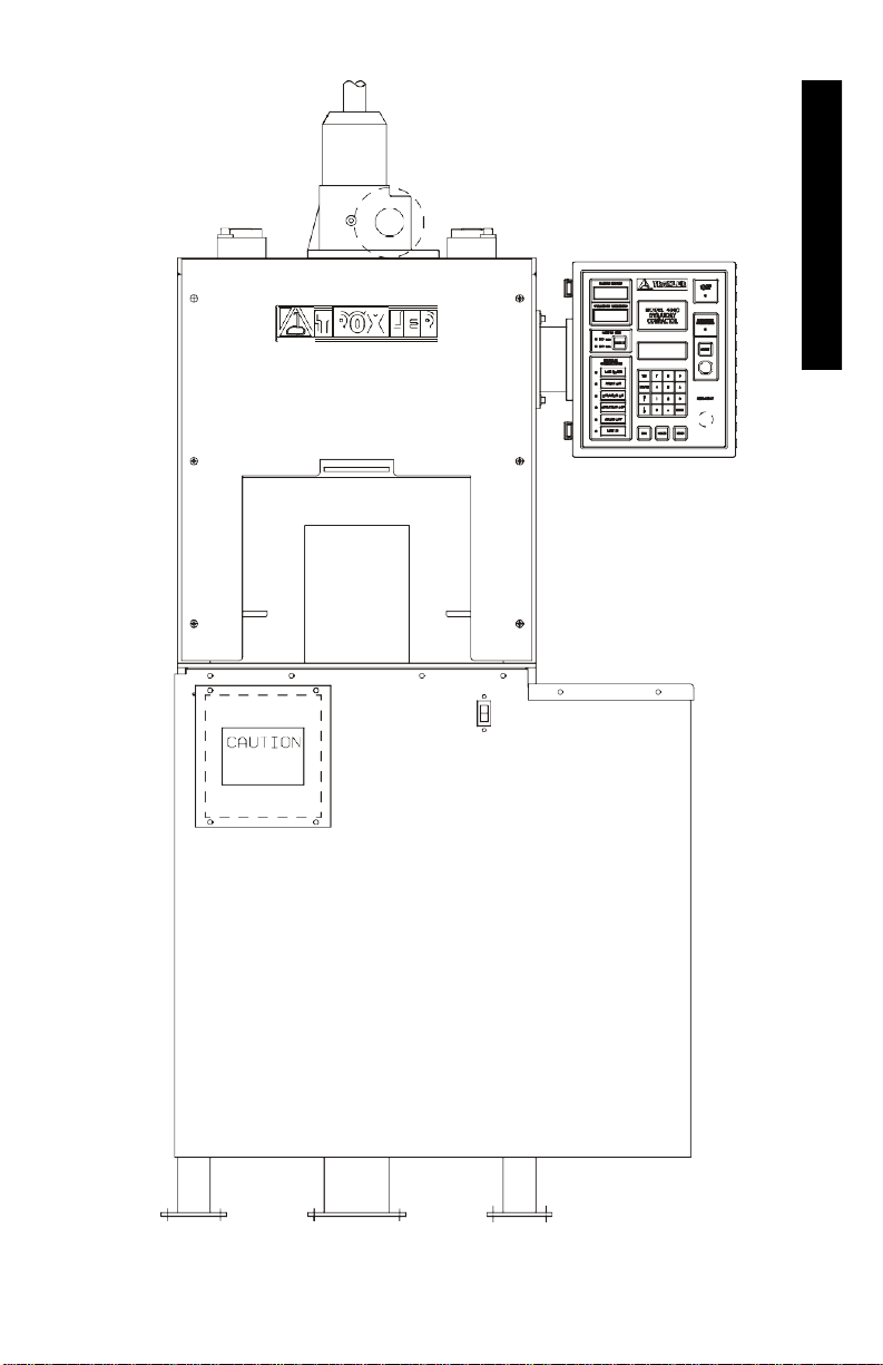
The Model 4140 Gyratory Compactor (Figure 1-1) meets or exceeds
all Federal Highway Administration (FHWA) SUPERPAVE™
specifications. The unit provides safe, reliable gyratory compaction
of asphalt specimens at a given consolidation pressure and angle of
gyration. The Model 4140 provides significant improvements over
other gyratory compactors in user safety, machine durability, noise
levels, heat output, and energy consumption.
For user safety, all rotating parts are covered and cannot be
physically accessed during compaction. The gyratory compactor
will not compact a specimen with either the shrouds improperly
positioned or the specimen chamber door open. The red
〈EMERGENCY〉safety button found in the lower right corner of
the control unit stops all moving parts and releases all forces that
could pose a threat to the user.
Two access doors, one on the front and one on the left side of the
compactor, provide easy access for angle verification and
adjustment. The shrouds allow access to the rotating parts and
machine control electronics for maintenance.
The Model 4140 requires little maintenance. To reduce the effects
of gyration on moving parts, the gyratory compactor requires some
lubrication. If necessary, the user may easily replace the turntable
insert. For a schedule of machine maintenance see page A-8.
To offer more flexible laboratory use, the Model 4140 provides two
compaction modes: automatic and manual. The automatic
compaction mode compacts the asphalt specimen with the touch of
a single key. The manual compaction mode allows the user to
control each phase of specimen compaction.
Model 4140
1-3
Figure 1-1. Model 4140 Gyratory Compactor
1. INTRODUCTION

1-4
The Model 4140 allows the user to produce either 150-mm diameter
or 100-mm diameter asphalt specimens. The user specifies the
number of gyrations (or end specimen height) and consolidation
pressure. The user can adjust the angle of gyration from 0.5 to 2.0°;
the default angle is 1.25°. When using the automatic compaction
option, the user may also choose to automatically send the gyration
versus height and/or pressure versus height data to a computer or a
printer. The unit also allows manual printing of the last six
compacted specimens. All output is in SI units as described in
ASTM E380-90A Standard for Metric Practice.
Before compaction the user heats both the loose asphalt and the
mold/puck assembly. The user then loads the mold with a
predetermined amount of hot mix asphalt (HMA) and places it on
the turntable. The initial angle is 0°. The specimen is now ready for
gyratory compaction.
After compacting the asphalt, the user removes the asphalt specimen
from the mold using the extruder furnished. Once removed from the
mold, the specimen is ready for testing.
NOTE
Do not attempt to operate the Model 4140 before
reading this manual and the safety warnings posted on
the unit. Troxler stresses that the user is solely
responsible for ensuring the safe use of the Model 4140.
Neither the manufacturer, its subsidiary,
representatives, or distributors can assume
responsibility for any mishaps, damage, or personal
injury which may occur from failure to observe the
safety warnings in this manual and posted on the unit.

Model 4140
1-5
PARTS AND ACCESSORIES
RAM COVER
CONTROL UNIT
ON/OFF
SWITCH
FRONT
ACCESS
DOOR
DOT MATRIX PRINTER
PUCK
MOLD EXTRUDER
Figure 1-2. Model 4140 Parts and Accessories
1. INTRODUCTION

1-6
The Model 4140 Gyratory Compactor includes the electrical and
mechanical parts necessary to continuously compact hot mix
asphalt. Use Figure 1-2 to locate and identify the following parts:
1.
The power switch is located under the worktable.
2.
The control unit, located on the right side of the compactor,
contains the control electronics for the gyratory compactor. It
provides the user interface with the Model 4140 and the
interface for optional equipment.
3.
The mold, with a puck inserted, receives the asphalt for making
specimens. The molds are manufactured from hardened steel to
resist wear and pitting, while limiting weight. Sizes: 150 mm
and 100 mm.
4.
The puck inserts in the mold. The puck is also made of
hardened steel to resist wear and pitting. Sizes: 150 mm and
100 mm.
5.
The extruder removes the compacted asphalt specimen from
the mold.
6.
The dot matrix printer allows the user to print data.
7.
The parallel printer cable (not shown) connects the control
unit to the dot matrix printer.
8.
The serial cable (not shown) connects the control unit to a
serial device, like a computer.
9.
The height calibration standard (not shown), used in
conjunction with a puck, aids in calibrating the specimen height
after setting the target pressure.
10.
The Model 4140 Manual of Operation and Maintenance (not
shown) provides the operating instructions for the compactor.
11.
The specimen papers (not shown) prevent the asphaltspecimen
from sticking to either the puck or the loading head. Sizes:
150 mm or 100 mm.

Model 4140
1-7
12.
The optional Performance Verification Kit (not shown) allows
the user to verify the pressure and angle calibrations. The
pressure and angle are initially calibrated at the factory.
13.
The optional temperature probe (not shown) allows the user to
test the initial temperature of a HMA specimen.
14.
The optional mold lifter (not shown) enables any user to easily
lift the mold in or out of the specimen chamber.
1. INTRODUCTION

1-8
UNPACKING AND INSPECTION
Upon receipt of the Model 4140 Gyratory Compactor from the
factory, a complete inspection and inventory should be performed.
If any parts or accessories appear damaged, notify the carrier and
your Troxler Representative immediately.
Check to see that the following are included:
♦
Model 4140 Gyratory Compactor
♦
Extruder
♦
Printer
♦
Parallel printer cable
♦
Serial cable
♦
Height calibration spacer
♦
Specimen papers (500 per package)
♦
Manual of Operation and Maintenance
Inspect each part for damage.
See page 2-3 for a guide to assembly.
Table of contents
Other Troxler Laboratory Equipment manuals

Popular Laboratory Equipment manuals by other brands


MYERSON
MYERSON HotShotElite instruction manual

Scion Instruments
Scion Instruments 436-GC Service manual

Metrohm
Metrohm 940 Professional IC Vario TWO manual

TSE
TSE Calorimetry PhenoMaster Hardware operating instructions

Chopin
Chopin Mixolab 2 Quick installation and first test

Thermo Scientific
Thermo Scientific Orbitrap Fusion Lumos Getting started guide


