Troxler PaveTracker Plus 2701-B User manual


ii
Troxler gauges are protected by U.S. and foreign patents.
The Model 2701-B PaveTrackerPlus is protected
by U.S. Patents 6,400,161 and 6,677,763.
Copyright 2004 – 2020
Troxler Electronic Laboratories, Inc.
All Rights Reserved
No part of this manual may be reproduced or transmitted in
any form or by any means, electronic or mechanical, including
photocopying, recording, or information storage and retrieval
systems, for any purpose without the express written
permission of Troxler Electronic Laboratories, Inc.
409 is a trademark of the Clorox Company.
Excel, HyperTerminal, Microsoft and Windows are registered
trademarks of Microsoft Corporation.
Fantastic is a trademark of Dow Consumer Products, Inc.
Goo Gone is a registered trademark of Magic American
Products Inc.
PaveTracker is a trademark of Troxler Electronic Laboratories,
Inc.
PN 113045
June 2020
Edition 6.2

Model 2701-B
iii
SAFETY ALERT SYMBOL
The Safety Alert Symbol shall appear within this manual. Wherever it
appears in this manual or on safety signs affixed to the machine, this is to
make all aware of the potential for personal injury and to be cautious
when these images are present.
Always observe all WARNING, CAUTION, and NOTE recommendations
listed within this manual before operating the machine.

iv
TROXLER SERVICE CENTERS
Troxler Corporate Headquarters
P.O. Box 12057
Research Triangle Park, NC 27709
Phone: 1.877.TROXLER (1.877.876.9537)
Outside the U.S.A.: +1.919.549.8661
Fax: +1.919.549.0761
Technical Support
Phone: 1.877.TROXLER
(1.877.876.9537)
TroxTechSupport@troxlerlabs.com
North Carolina Service Center
3008 E. Cornwallis Road
Research Triangle Park, NC 27709
Phone: +1.919.549.8661
Fax: +1.919.549.0761
TroxTechSupport@troxlerlabs.com
Florida Office & Service Center
2376 Forsyth Road
Orlando, FL 32807
Phone: +1.407.681.4221
Fax: +1.407.681.3188
TroxTechSupport@troxlerlabs.com
Midwestern Office & Service Center
1430 Brook Drive
Downers Grove, IL 60515
Phone: +1.630.261.9304
Fax: +1.630.261.9341
TroxTechSupport@troxlerlabs.com
Western Office & Service Center
11300 Sanders Drive, Suite 7
Rancho Cordova, CA 95742
Phone: +1.916.631.0234
Fax: +1.916.631.0541
TroxTechSupport@troxlerlabs.com
Southwestern Office &
Service Center
2016 East Randol Mill Rd., Suite 406
Arlington, TX 76011
Phone: +1.817.275.0571
Fax: +1.817.275.8562
TroxTechSupport@troxlerlabs.com
Troxler Europe & Service Center
Waldstrasse 4, D.82239 Alling nr.
Munich, Germany
Phone: ++ 49.8141.71063
Fax: ++49.8141.80731
troxler@t-online.de
Troxler Electronic Technologies
(Zhangjiagang)
1F, Bldg G, No. 1 Guotai North Road
ZJG, China, 215600
Phone: 0086.512.56793702
Fax: 0086.512.56793701
kjin@troxlerlabs.cn
To locate an independent, Troxler-authorized service partner
near you, call 1.877.TROXLER (1.877.876.9537).

Model 2701-B
v
HOW TO USE THIS MANUAL
Congratulations on the purchase of the Troxler Model 2701-
B PaveTrackerPlus. Troxler, the leader in density gauge
technology, now offers the PaveTracker Plus, an
electromagnetic sensing device that quickly gives an
indication of the density of asphalt pavement.
The Model 2701-B Manual of Operation and Instruction
contains information on safely using this gauge. Also included
in this manual are safety warnings, gauge setup,
troubleshooting, and general maintenance.

vi
WARNING
Warnings indicate conditions or procedures that,
if not followed correctly, may cause personal
injury.
CAUTION
Cautions indicate conditions or procedures that, if not
followed correctly, may cause equipment damage.
DI SPLAY- Typest yl e an
d shadi ng used t o si m
ul at e t he cont r ol pan
el di spl ay
CONVENTIONS USED IN THIS MANUAL
Throughout this manual the following symbols and special
formatting are used to reveal the purpose of the text.
NOTE
Notes indicate important information that must be read to
ensure proper operation.
〈KEY〉This style indicates a key or character to press on the
keypad.
1. Indicates a procedure with multiple steps.
♦Indicates a list of things needed (such as equipment)
or important points to know.
Indicates that more than one option is available.
Carefully select the option that applies.

Model 2701-B
vii
ABOUT THIS MANUAL
The Model 2701-B Manual of Operation and Instruction
provides detailed information about the PaveTracker Plus
gauge. The manual includes product safety information, as
well as instructions for the proper installation and use of the
PaveTracker Plus.
This manual is organized as follows:
Chapter 1, Introduction – Provides a brief overview of the
unit and its features; a list of parts and accessories; and
instructions for unpacking and inspection.
Chapter 2, Getting Started – Describes the gauges keypad
and provides instructions for setting up, starting, and
operating the unit.
Chapter 3, Adjusting Measurements – Provides instructions
for using offsets and mix calibration.
Chapter 4, Using the Gauge – Provides instructions for
referencing the gauge and using offsets.
Chapter 5, Using the Gauge – Provides instructions for
referencing using the Projects function.
Appendix A, Troubleshooting and Service – Provides
maintenance and service information, as well as instructions
for basic troubleshooting.
Appendix B, Menu Map – Shows a map of the gauge’s Setup
and Target menus.
Appendix C, Specifications – Contains the mechanical,
electrical, and environmental performance specifications.
Appendix D, Global Positioning System (GPS) – Contains
information and specifications for the GPS receiver.

vii
EU DECLARATION OF CONFORMITY
Application of Council EMC Directive 89/336/EEC.
NOTE
The Low Voltage Directive 73/23/EEC does not apply to
the Model 2701-B PaveTracker Plus gauge because there
are no voltages greater than 75 V dc that are accessible by
the operator.
Standards to which Conformity is Declared:
EN 55011:1998+A1:1999+A2:2002 – Industrial, Scientific,
and Medical (ISM) Radio Frequency Equipment
EN 61326:1997+A1:1998+A2:2001+A3:2002 – Electrical
Equipment for Measurement, Control, and Laboratory
Use
Manufacturer: Troxler Electronic Laboratories, Inc.
P.O. Box 12057, 3008 Cornwallis
Road
Research Triangle Park, North
Carolina
27709 U.S.A.
Apparatus: Model 2701-B PaveTracker Plus
Year of Declaration: 2006


viii
FCC REGULATIONS
Troxler’s Model 2701-B PaveTrackerPlus has been tested
and found to comply with the limits for Industrial, Scientific,
and Medical Devices pursuant to Part 18 of Federal
Communications Commission (FCC) Rules. These limits are
designed to provide reasonable protection against harmful
interference when the equipment is operated in a commercial
environment. This equipment generates, uses, and can radiate
radio frequency energy and, if not used in accordance with
this instruction manual, may cause harmful interference to
radio communications. Operation of the equipment in a
residential area may cause harmful interference. It is advised
that operation in residential areas be as brief as practicable to
minimize the potential for interference.

Model 2701-B
ix
TABLE OF CONTENTS
CHAPTER 1. INTRODUCTION
Introduction............................................................................................. 1–2
Features .................................................................................................... 1–4
Gauge Parts and Accessories............................................................ 1–6
Unpacking and Inspection................................................................. 1–7
CHAPTER 2. GETTING STARTED
Keypad....................................................................................................... 2–2
Turning the PaveTracker Plus On .................................................... 2–4
Status ......................................................................................................... 2–6
Setup Menu............................................................................................. 2–7
Target ......................................................................................................2–15
Mode........................................................................................................2–18
CHAPTER 3. ADJUSTING MEASUREMENTS
Introduction ............................................................................................ 3–2
Offset ......................................................................................................... 3–3
Mix Calibration....................................................................................... 3–6
CHAPTER 4. USING THE GAUGE
Referencing the Gauge ....................................................................... 4–2
Preparing a Test Site ............................................................................ 4–4
Taking Measurements......................................................................... 4–4
Recall........................................................................................................4–12
CHAPTER 5. PROJECT DATA
Handling Project Data ..........................................................................5-2
Storing Data .......................................................................................... 5-10

x
APPENDIX A. TROUBLESHOOTING AND SERVICE
Troubleshooting .................................................................................... A-2
Internal Gauge Temperature............................................................. A-4
Batteries .................................................................................................... A-5
Cleaning the Base and Top Shell..................................................... A-7
Replacing the Protective Cover........................................................ A-8
Replacement Parts..............................................................................A-10
Returning the Gauge for Service...................................................A-11
APPENDIX B. MENU MAP
Menu Map Description ........................................................................B-2
APPENDIX C. SPECIFICATIONS
Measurement Specifications............................................................. C-2
Electrical Specifications....................................................................... C-3
Mechanical Specifications.................................................................. C-4
INDEX
WARRANTY
LIST OF FIGURES
Figure Title Page
Figure 1–1. Model 2701-B PaveTracker Plus...............................1–3
Figure 2–1. Model 2701-B Keypad ................................................. 2–2
Figure 5–1. Model 2701-B Menu Map ...........................................5-3
LIST OF TABLES
Table Title Page
Table 2–1. Model 2701-B Keypad Functions .............................. 2–3
Table D-1. GPS Position Accuracy...................................................D-4

Model 2701-B
1–1
C
Ch
ha
ap
pt
te
er
r 1
1:
:
I
In
nt
tr
ro
od
du
uc
ct
ti
io
on
n
This chapter covers the following topics and tasks:
An introduction to your new PaveTracker Plus
Included parts and accessories
Inspection and unpacking
Assembly and first-time use
1. INTRODUCTION

1–2
Introduction
The Model 2701-B PaveTracker Plus is an electromagnetic
sensing device that quickly gives an indication of the density
of asphalt pavement.
The advanced technology in the patented PaveTracker Plus
allows rapid and reliable measurements. The PaveTracker Plus
can be used on existing asphalt pavements or on freshly
placed mats. The unit is ideal for performing quick quality
control measurements to check for segregation, areas of low
density, and overall pavement uniformity.
The PaveTracker Plus is a precision device that is designed to
provide many years of trouble-free service. As any precision
device, the PaveTracker Plus requires reasonable care and
maintenance to ensure its accuracy and reliability. The user
should:
♦Keep the unit clean and free of all road debris.
♦Return the unit to Troxler for yearly re-calibration and
inspection.
♦Ensure that the unit remains sealed at all times. There are
no field-serviceable components inside the unit.
Opening the case will affect the integrity of the unit and
therefore will void the warranty.
Model 2701-B
1–3
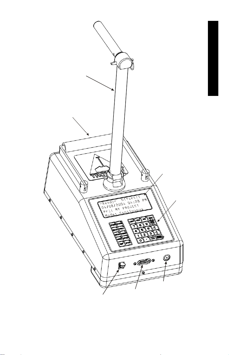
HANDLE
CARRYING
HANDLE
DISPLAY
KEYPAD
BATTERY
CHARGER
INPUT
SERIAL
PORT
POWER
SWITCH
Figure 1–1. Model 2701-B PaveTracker Plus
1. INTRODUCTION

1–4
Features
The PaveTracker Plus (see Figure 1–1) incorporates a number
of features that provide unmatched efficiency, usability, and
flexibility.
The PaveTracker Plus takes density measurements using
electromagnetic sensing technology, eliminating the need for
government licenses or special training. Measurements are
completed within two seconds, saving time and money.
The unit’s memory can store approximately 1000 readings
for later viewing, printing, or downloading.
Both the 30-button keypad and 4 x 20 liquid crystal display
(LCD) screen are backlit, making them easy to see, day or
night.
The gauge includes a replaceable, protective, adhesive-
backed bottom cover disc on its bottom surface. The
protective cover provides thermal protection for the gauge’s
internal components and protects the bottom surface of the
gauge against wear.
The carrying case for the Model 2701-B includes a built-in
reference standard, which provides a density measurement
standard for referencing the gauge.
The PaveTracker Plus’s advanced software provides three test
modes (continuous, averaging, and segregation) for greater
flexibility and multiple applications. The software also
provides automatic calculations (average density, percent
maximum density, percent air voids, and so on) for greater
ease of use.

Model 2701-B
1–5
The PaveTracker allows the operator to specify the layer
thickness; the value entered is stored with other
measurement data.
Measurements can be adjusted using a density offset or mix
calibration (which includes slope and intercept values) to
increase accuracy on specific materials.
Both an ac charger and a dc adapter are included with the
PaveTracker Plus, enabling the unit to be recharged from an
ac outlet or a 12 V dc system.
The gauge features two audible indicators, an internally
mounted beeper, as well as a louder, external one mounted on
its underside. The internal beeper emits a short tone in
response to a valid keystroke on the keypad. It sounds a
longer tone when the operator presses an invalid key or if the
gauge displays an error message. The external beeper
performs the same functions and can be enabled or disabled
as desired by the operator.
A serial communications port is mounted on the front of the
gauge. The serial port is used to output data to a serial device,
such as a computer or printer.
The gauge can be equipped with an optional global
positioning system (GPS) receiver. The GPS receiver enables
the gauge to store precise GPS coordinates, along with the
standard date and time stamp for each measurement.
The gauge features two handles. The right-angle handle is
used to move and position the gauge while taking
measurements. A second carrying handle is provided for ease
of transporting and positioning the gauge. An optional
telescoping handle (PN 113017) is also available.
1. INTRODUCTION

1–6
Gauge Parts and Accessories
1. The gauge is the portable electromagnetic sensing device
containing all electronic modules and a rechargeable
battery pack.
2. The carrying case for the Model 2701-B includes a built-
in reference standard, which provides a density
measurement standard for taking reference readings.
3. The ac charger and dc adapter are used to charge the
gauge batteries. The ac charger accepts 100 – 240 V ac, 47
– 63 Hz and supplies 12 V dc at 1.8 A. The dc adapter
allows recharging from a 12 V dc system, such as a vehicle
cigarette lighter.
4. A printer (optional) connects to the gauge for printing
data.

Model 2701-B
1–7
Unpacking and Inspection
NOTE
To ensure the safe return of the PaveTracker Plus to
Troxler for repair or maintenance, please keep the original
shipping boxes and all packing materials.
Upon receipt of the gauge from the factory:
1. Perform a complete inspection and inventory. If the
shipping case and/or any other part or accessory appears
damaged, notify the carrier and your Troxler
representative immediately.
2. Check the shipping case for the following:
♦Model 2701-B PaveTracker Plus
♦Carrying Case (PN 113034.1000)
♦Handle (PN 113210)
♦AC Charger (PN 110403)
♦DC Adapter (PN 104156)
♦2701-B Cover Kit (PN 113107), containing replacement
bottom covers and cleaning wipes
♦Manual of Operation and Instruction (PN 113045)
3. Lift the gauge from the carrying case and inspect the
outside surface for damage
1. INTRODUCTION

1–8
NOTES
This manual suits for next models
2
Table of contents
Other Troxler Laboratory Equipment manuals


