TSE Calorimetry PhenoMaster User manual

2PhenoMaster | Hardware Operating Instructions
Copyright © 2018 TSE Systems International Group - All rights reserved
These operating instructions, including all parts thereof, are protected by copyright. Any infringement
of the copyright laws without the written agreement of the TSE Systems GmbH is illegal and subject
to due penalty at law. This applies in particular to their reproduction, processing, translation,
microfilming as well as to their storage and processing in electronic systems. This regulation does not
apply to reproductions for internal use. Further examples of these operating instructions are available
and can be ordered from us; a charge will be made for these extra copies.
PM15_HW_CaloSys_e_01.docx DJM - Specifications subject to change without notice -
info@TSE-Systems.com www.TSE-Systems.com

CaloSys Modules3
Table of Contents
1. Introduction .....................................................................................................................7
2. Instructions for safe Operation.........................................................................................8
2.1. General Safety Instructions .............................................................................................8
2.1.1. Proper Use......................................................................................................................8
3. Operating Principle..........................................................................................................9
4. PC Requirements............................................................................................................9
5. Installation Drivers, Interface, Software.........................................................................10
5.1. USB Interface................................................................................................................10
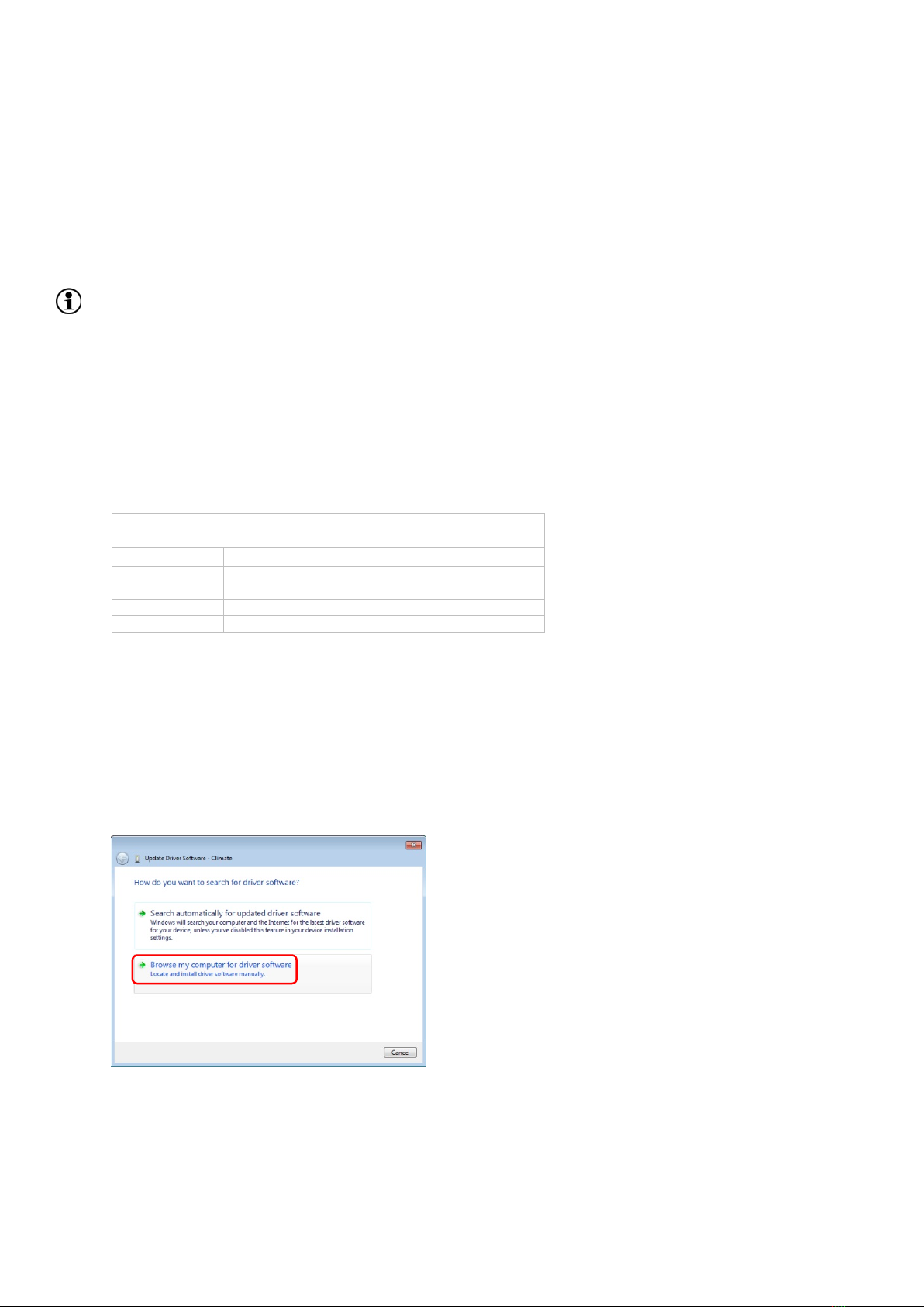
5.1.1. Installing *.inf file (TSE USB Adapter*)..........................................................................10
5.2. WireOne Driver..............................................................................................................12
6. Connecting Devices - General.......................................................................................16
7. Cage Rack ....................................................................................................................16
8. System Software...........................................................................................................16
9. Performing a Measurement...........................................................................................16
10. Maintenance and Cleaning............................................................................................17
10.1. Cage .............................................................................................................................17
10.1.1. Cage Lid........................................................................................................................17
10.1.1.1. Calorimetry Cage Lid.....................................................................................................17
10.2. Air Supply Pump............................................................................................................20
10.2.1. Exchanging Filter...........................................................................................................21
10.2.2. Overpressure Valve.......................................................................................................22
10.2.3. Chamber Block Change ................................................................................................23
10.2.4. Troubleshooting.............................................................................................................24
10.3. Vacuum Pump...............................................................................................................25
10.3.1. Chamber Block Change ................................................................................................25
10.4. Exchanging Protection Air Filter ....................................................................................25
10.5. Exchanging Disk Filter...................................................................................................26
10.6. Air Drying Unit...............................................................................................................27
10.7. Tubing...........................................................................................................................27
10.8. Replacing Flowmeter Battery.........................................................................................28
11. Calorimetry Measurement .............................................................................................29
11.1. Overview Devices and Connections..............................................................................29
11.1.1. Push Principle Respirometry (Overpressure Principle)..................................................30
11.1.1.1. CaloSys Module to be operated with manual Calibration...............................................30
11.1.1.2. CaloSys Module to be operated with automatic or manual Calibration ..........................32
11.1.1.3. CaloSys Module including multiple Calorimetry Control Units........................................33
11.1.2. Pull Principle Respirometry (Underpressure Principle) ..................................................36
11.1.2.1. CaloSys Module to be operated with manual Calibration...............................................36
11.1.2.2. CaloSys Module to be operated with automatic or manual Calibration ..........................38
11.1.2.3. CaloSys Module including multiple High-Speed Sensor Units .......................................40
11.2. Calorimetry Process Control Unit ..................................................................................43
11.2.1. Connections Calorimetry Process Control Unit..............................................................44
11.2.1.1. Connections Calorimetry Master Process Control Unit..................................................45
11.2.1.2. Connections Calorimetry Master Process Control and High-Speed Sensor Unit............46
11.2.1.3. Connections Calorimetry Slave Process Control Unit....................................................47
11.2.2. Mass Flow Controllers in Calorimetry Control Unit.........................................................47
11.2.3. Setting Sample Flow on Calorimetry Master Control Unit..............................................49
11.2.4. Combination Sensor for O2 and CO2 Concentration in Calorimetry Master Control Unit49
11.2.4.1. O2 Sensor - Working Principle ......................................................................................49
11.2.4.2. CO2 Sensor - Working Principle....................................................................................50
11.2.5. Temperature Sensor .....................................................................................................50
11.2.5.1. Analogous Temperature Sensor....................................................................................50
info@TSE-Systems.com www.TSE-Systems.com

4PhenoMaster | Hardware Operating Instructions
11.2.5.2. Digital Temperature Sensor...........................................................................................51
11.3. Calibration Master Process Control Unit........................................................................51
11.3.1. Connections Calibration Master Process Control Unit ...................................................51
11.3.2. Connections Calibration Slave Process Control Unit .....................................................53
11.4. Sample Switch Unit.......................................................................................................54
11.4.1. Connections Sample Switch Unit...................................................................................54
11.4.2. Information about Reference Air....................................................................................55
11.5. Connecting PC..............................................................................................................55
11.6. Air Supply Pump............................................................................................................55
11.6.1. General .........................................................................................................................57
11.6.2. Installation.....................................................................................................................57
11.6.3. Connections..................................................................................................................57
11.6.4. Operation ......................................................................................................................58
11.7. Vacuum Pump...............................................................................................................59
11.7.1. Installation.....................................................................................................................60
11.7.2. Connections..................................................................................................................61
11.7.3. Operation ......................................................................................................................62
11.8. Protection Air Filter........................................................................................................62
11.8.1. Connections Protection Air Filter ...................................................................................62
11.9. Air Drying Unit...............................................................................................................64
11.9.1.1. 1x Air Drying Unit ..........................................................................................................65
11.9.1.2. 4x Air Drying Unit ..........................................................................................................66
11.9.2. Connections Air Drying Unit...........................................................................................67
Appendix
A. Example configurations
B. Example electrical requirements
info@TSE-Systems.com www.TSE-Systems.com

CaloSys Modules5
List of Figures
Fig. 1 Default installation path – Drivers destination location...........................................................10
Fig. 2 Calorimetry cage lid...............................................................................................................19
Fig. 3 Air pump (Top view)...............................................................................................................21
Fig. 4 Filter cover removed..............................................................................................................21
Fig. 5 Filter removed........................................................................................................................22
Fig. 6 Diaphragm protective switch deactivated...............................................................................24
Fig. 7 Diaphragm protective switch activated (Pump powered OFF)................................................24
Fig. 8 Diaphragm protective switch deactivated...............................................................................24
Fig. 9 Disassembling discus filter (1) ...............................................................................................26
Fig. 10 Disassembling discus filter (2) .............................................................................................27
Fig. 11 Replacement of flowmeter battery........................................................................................28
Fig. 12 Schematic diagram of CaloSys module – Push principle respirometry – w/o Calibration Unit –
Analog read-out – 8-place system............................................................................................30
Fig. 13 Schematic diagram of CaloSys module – Push principle respirometry – w/ Calibration Control
Unit – 8-place system...............................................................................................................32
Fig. 14 Schematic diagram of CaloSys module - Push principle respirometry - w/ multiple Calorimetry
Control Units - Digital read-out - 8-place system.......................................................................34
Fig. 15 Schematic diagram of CaloSys module - Pull principle respirometry - w/o Calibration Control
Unit - Analog read-out - 8-place system....................................................................................36
Fig. 16 Schematic diagram of CaloSys module - Pull principle respirometry - w/ Calibration Control
Unit - 8-place system................................................................................................................38
Fig. 17 Schematic diagram of CaloSys module - Pull principle respirometry - w/ multiple High-Speed
Sensor Units - Digital read-out - 32-place system.....................................................................41
Fig. 18 Calorimetry Master Control Unit...........................................................................................44
Fig. 19 Calorimetry Master Control Unit - Rear view........................................................................44
Fig. 20 Calorimetry Master Control Unit - Rear view........................................................................46
Fig. 21 Calorimetry Slave Control Unit - Rear view..........................................................................47
Fig. 22 Flowmeter............................................................................................................................48
Fig. 23 Rotary knob MFC sample flow at the Calorimetry Control Unit.............................................49
Fig. 24 Calibration Master Control Unit - Front panel.......................................................................51
Fig. 25 Gas pressure display...........................................................................................................52
Fig. 26 Calibration Master Control Unit - Rear panel........................................................................52
Fig. 27 Calibration Slave Control Unit..............................................................................................53
Fig. 28 Ports/Connectors of Sample Switch Unit for 16 animal cages..............................................54
Fig. 29 PC ports...............................................................................................................................55
Fig. 30 Air supply pump...................................................................................................................56
Fig. 31 Pressure control valve .........................................................................................................58
Fig. 32 Vacuum pump .....................................................................................................................59
Fig. 33 Pressure control valve .........................................................................................................61
Fig. 34 Connections protection air filter............................................................................................63
Fig. 35 Flow direction ......................................................................................................................63
Fig. 36 1x Air Drying Unit w/ separating bottle.................................................................................65
Fig. 37 4x Air Drying Unit.................................................................................................................66
info@TSE-Systems.com www.TSE-Systems.com

CaloSys Modules7
TSE PhenoMaster System
for small Laboratory Animals
1. Introduction
System configuration
These operating instructions describe devices and features of the PhenoMaster Phenotyping
Research Platform of TSE Systems. Some devices and features may not be available on your
system. For your individual system configuration, please refer to your order confirmation. If you have
questions or need assistance, please contact TSE Service.
See Hardware Operating Instructions - Core Modules, Section "Introduction".
info@TSE-Systems.com www.TSE-Systems.com

8PhenoMaster | Hardware Operating Instructions
2. Instructions for safe Operation
See Hardware Operating Instructions - Core Modules, Section "Instructions for safe Operation".
2.1. General Safety Instructions
Proper Use2.1.1.
NOTICE - Reduced lifetime!
If Calorimetry Process Control Units and Air Pumps are powered ON without operating the
system, this may reduce lifetime of devices.
•Always run system software when devices are powered ON.
•Power OFF devices after use.
NOTICE – Reduced lifetime!
If High-Speed Sensor Unit is powered ON without operating the system, contamination may
damage the sensors.
•During operating mode of High-Speed Sensor Unit, ensure that…
o…its sensors are supplied with air from reference gas cylinder continuously.
o…all other devices of the CaloSys module entered operating mode as well.
o…PhenoMaster software is running.
•Power OFF High-Speed Sensor Unit after use.
NOTICE - Reduced lifetime!
If excess heat produced by the Air Drying Units cannot dissipate to the outside, this may
reduce lifetime.
Ensure that the device is properly ventilated:
•Min. distance:
oAir Drying Unit - Wall: >=150…200mm (>=5.91…7.87inch)
oAir Drying Unit - Other devices: >=150…200mm (>=5.91…7.87inch).
NOTICE – Reduced lifetime!
If Calorimetry Process Control Units and Air Pumps are powered ON while there is a leakage
in the sample line, this may reduce lifetime of devices.
•After you have discarded condensed water, carefully reconnect collection vessel to 1x Air
Drying Unit and reconnect separating bottle to tubing.
•Select "Status/Calo" and check for proper "SampleFlow” on "Calo Current Values" dialog (see
Software Operating Instructions – Calorimetry, Section "Status Menu, Calo").
NOTICE – Reduced lifetime!
If Calorimetry Process Control Units and Air Pumps are powered ON while there is a leakage
in the sample line, this may reduce lifetime of devices.
•Never remove collection vessels from the 4x Air Drying Unit. Drain off condensed water via
collection vessel tubing only.
•After you have discarded condensed water of separating bottle, carefully reconnect bottle to
tubing.
•Select "Status/Calo" and check for proper "SampleFlow” on "Calo Current Values" dialog (see
Software Operating Instructions – Calorimetry, Section "Status Menu, Calo").
info@TSE-Systems.com www.TSE-Systems.com

10 PhenoMaster | Hardware Operating Instructions
5. Installation Drivers, Interface, Software
See Hardware Operating Instructions - Core Modules, Section "Installation Drivers, Interface,
Software".
5.1. USB Interface
USB interface
If your Calibration Control Unit has an USB connection to the PC, no PCI interface is required.
Installing *.inf file (TSE USB Adapter*)5.1.1.
It is assumed that…
•…the Calibration Control Unit has already been connected to the PC.
•…you are logged into the PC as a user with administrator rights and have access to the
device driver.
Installation Path
OS
Default Installation Path
Windows7 (32bit)
C:\Program Files\TSE\PhenoMaster\Drivers\Bin_x86
Windows7 (64bit)
C:\Program Files (x86)\TSE\PhenoMaster\Drivers\Bin_x64
Windows10 (32bit)
C:\Program Files\TSE\PhenoMaster\Drivers\Bin_x86
Windows10 (64bit)
C:\Program Files (x86)\TSE\PhenoMaster\Drivers\Bin_x64
Fig. 1 Default installation path – Drivers destination location
Windows7
•Select "Windows Start button/Control Panel/Device Manager".
•Check hardware descriptions. With the right hand mouse-key, click on list item marked with a
yellow attention symbol.
•Select "Update Driver Software…"
•Select "Browse my computer for driver software".
•Browse for driver´s installation path and press "Next".
info@TSE-Systems.com www.TSE-Systems.com

16 PhenoMaster | Hardware Operating Instructions
6. Connecting Devices - General
See Hardware Operating Instructions - Core Modules, Section "Connecting Devices - General".
7. Cage Rack
See Hardware Operating Instructions - Core Modules, Section "Cage Rack".
8. System Software
See Hardware Operating Instructions - Core Modules, Section "System Software".
9. Performing a Measurement
See Hardware Operating Instructions - Core Modules, Section "Performing a Measurement".
info@TSE-Systems.com www.TSE-Systems.com

CaloSys Modules17
10. Maintenance and Cleaning
See Hardware Operating Instructions - Core Modules, Section "Maintenance and Cleaning".
10.1. Cage
Cage Lid10.1.1.
See Hardware Operating Instructions - Core Modules, Section "Maintenance and Cleaning, Cage,
Cage Lid".
10.1.1.1. Calorimetry Cage Lid
Prerequisites
In order to clean and decontaminate calorimetry cage lids, it is necessary to dismantle them
completely.
WARNING
Eye Injuries
When the quick-action coupling plug is loosened, it may pops out and injure your eyes.
Hold the quick-action coupling plug tightly when loosening it and do NOT bend down over it.
info@TSE-Systems.com www.TSE-Systems.com

CaloSys Modules19
Fig. 2 Calorimetry cage lid
Device
Material
Quantity
1
Temperature sensor sealing
EPDM
1
2
Training lid*
Makrolon®,clear-transparent
1
3
Baffle
1.4031 steel
1
4
Cover lid*
Makrolon®, clear-transparent
1
5
Adapter sealing
EPDM 60 Shore A
2
6
Frame sealing
EPDM 60 Shore A
1
7
Frame
POM, black
1
8
Adapter (push principle)**
POM, black
1
9
Adapter (pull principle)**
POM, black
1
10
Nozzle
POM, black
1
11
Lid
Makrolon®, clear-transparent
1
12
Holder3
POM, black
2
13
Holder2
POM, black
2
14
Holder1
1.4031 steel
4
15
Angle bracket
POM, black
2
16
Sealing**
EPDM
1
17
Quick-action coupling 1/8
1.4031 steel
3
18
Round-head screw w/ cross recess
Makrolon®, clear-transparent
12
19
Countersunk screw w/ cross recess PC M3x6.4
Makrolon®, clear-transparent
4
20
Countersunk screw w/ cross recess PC M2x4
Makrolon®, clear-transparent
4
21
Induction disk w/ sinking
Sm2Co17
4
22
Resilient pressure piece
1.4031 steel
4
23
Component assembly digital temperature
sensor
Electronics 1
24
Countersunk screw M2x8 cross recess
1.4031 steel
20
25
Lens head screw M3x18 cross recess
1.4031 steel
12
26
Lens head screw M3x10 cross recess
1.4031 steel
4
27
Frame swivel holder
POM, black
1
*2 options for lids: Either position 2 or 4
**2 options for adapters: Either position 8 or 9
10
23
1
5
4
5
9
10
23
1
5
4
5
8
2
24
3
25
26
22
18
20
11
24
27
Pull system configuration
Push system configuration
Training configuration
Swivel configuration
info@TSE-Systems.com www.TSE-Systems.com

20 PhenoMaster | Hardware Operating Instructions
Susceptibility against liquids
The quick-action couplings for air inlet and air outlet, sampling, and particularly the temperature
sensor of the cage, should NOT come into contact with water, cleaning liquids, etc.
The calorimetry cage lid devices must be decontaminated with a method approved for use on the
calorimetry cage lid device material (hints, see table below).
Decontamination Calorimetry Cage Lid
Material
Autoclave
Gas Sterilization
Ethylene Oxide (ETO)
H2O2 Gas Plasma
Sterilization
Disinfectants
Polycarbonate (e.g.
Makrolon®)
Autoclave temperature:
<=121°C (<=249.8°F)
Sterilization temperatures
>125°C (>257°F) during
autoclaving can deform
Makrolon® shaped parts.
Generally, Makrolon®
shaped parts can be
sterilized several times
before the mechanical
stability will be reduced -
due to the increasing
chemical degradation - to
a level, which is NOT
sufficient for
miscellaneous
applications.
Applicable sterilization
procedures use undiluted
ETO as well as mixings
including carbon dioxide
or inert gas - 10...20%
ETO / 90...80% other gas.
Sterilization temperature
<=65°C (<=149°F).
With increasing number of
sterilization procedures, a
slight embrittlement
associated with fissuring
may occur.
Applicable
2% Peracetic acid
applicable for Makrolon®
shaped parts.
Polycarbonate, glued
Not specified.
Depends on (1) glue and
(2) gluing procedure.
Not specified.
Depends on (1) glue and
(2) gluing procedure.
Not specified.
Depends on (1) glue and
(2) gluing procedure.
Not specified.
Depends on (1) glue and
(2) gluing procedure.
Electronics
NOT applicable
NOT applicable
Applicable
Observe instructions of
third party electronic
device manufacturer.
NOT applicable
Silicone foam
Autoclave temperature:
<=121°C (<=249.8°F)
Not specified.
Not specified.
Not specified.
10.2. Air Supply Pump
System configuration
This section describes cleaning and maintenance of air supply pumps of CaloSys modules working
with push principle (see Section 11.1.1). For instructions about maintenance of vacuum pumps of
CaloSys modules working with pull principle (see Section 11.1.2), see Section 10.3.
DANGER
Hazardous voltage
Improper use of the pump can cause electrical shock or start a fire.
•Repairs and maintenance work must be carried out by suitably qualified personnel only.
•Always unplug the device from the mains before carrying out repairs and maintenance.
info@TSE-Systems.com www.TSE-Systems.com
Table of contents
Other TSE Laboratory Equipment manuals
Popular Laboratory Equipment manuals by other brands

Carestream
Carestream Dryview 6850 user guide

Miele professional
Miele professional E 957 operating instructions

IKA
IKA Lab Disc IKAMAG operating instructions

Thermo Scientific
Thermo Scientific Sorvall Legend X1R instruction manual

NEW BRUNSWICK SCIENTIFIC
NEW BRUNSWICK SCIENTIFIC MP-1000 Pourmatic Guide to operations

Amsco
Amsco Century Operator's manual