manuals.online logo
Brands
  1. Home
  2. •
  3. Brands
  4. •
  5. Troxler
  6. •
  7. Measuring Instrument
  8. •
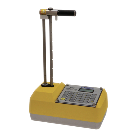
  9. Troxler EGauge Combo 4540 User manual

Troxler EGauge Combo 4540 User manual

5 6 Edition 1.1, May 2021 PN 128992
STEP 5 – TAKE MEASUREMENTS
Always begin with handle in SAFE position. Ensure
that the handle is in the SAFE position by firmly
tapping down on the handle without engaging the
trigger.
We recommend 2 minutes for measurement time and
1 minute for background time. (Setup menu)
The gauge can be set to receive moisture values from
an outside device or by keypad entry. You can also
choose to perform the moisture measurement before
or after the density measurement. Press Setup,choose
4. Moisture Input, then choose your method / order
desired.
Prepare the test site as described in step 4. If using
the moisture probe, drive the drill rod to at least 15 cm
(6 in).
PERFORMING DENSITY MEASUREMENTS
1
1.
.
Place the gauge on the test site with the
handle in the Safe position and press
〈ENTER/START〉. Follow the prompts on
the screen to either lower the handle to the
desired measure depth or wait for the 15-
second initialization phase to complete (this
will occur approx. every 10 min. or as
programmed). Then lower handle to the
desired measurement depth, carefully
seating the handle in the proper notch and
press 〈ENTER/START〉.
2
2.
.
After count time, (when prompted) select
the active background count by answering
Yes to the displayed question or take a new
one by answering No to the question.If
taking a new background count, move the
source rod to background position and
press 〈ENTER/START〉. For accurate density
measurement of soils and aggregates, a
new background count should be taken at
the first test site of the day and on a new
material or a new jobsite during the day.
3
3.
.
After the measurement, raise the handle.
The gauge displays the measurement
results or prompts for the moisture reading.
If a moisture reading is to be done, see the
next section. To store the reading, press
〈STORE〉.
After taking readings, lift the gauge from the test site
by the source rod handle. This returns the source rod
to the SAFE position. When not taking readings,
always keep the source rod in the SAFE position.
PERFORMING MOISTURE MEASUREMENTS IN
SOIL MODE
1
1.
.
When prompted by the 4540 gauge, insert
moisture probe into the hole until the base
plate contacts soil surface. The probe should
fit tightly in the hole, some resistance should
be felt when lowering it.
2
2.
.
Power the probe on (green light illuminates).
The blue light will remain solid when Bluetooth
connectivity is established.
3
3.
.
Press Enter on gauge keypad to perform
moisture reading, wait a few seconds then
press Enter on the keypad again to accept
the moisture reading. See the Guide for the
Model 6760 Moisture Probe for more
details on operation.
4
4.
.
Carefully remove the probe and set aside.
USING THE OFFSET FUNCTION
The gauge readings can be adjusted using an offset.
The gauge applies the offset to measurements until
the offset is disabled or the gauge is turned off. The
gauge provides moisture density and trench offsets.
Press 〈OFFSET〉to access the Offset menu.
MORE INFORMATION
The user manual provides more information about the
gauge’s functions and use.
i. Model 6760 Quick Reference Guide
ii. 6760 Technical Notes
Model 4540 Quick Reference Guide PN 128992, Edition, 1.1. May 2021
Model 4540
Soil & Asphalt Density Gauge
EGauge™Combo
QUICK
REFERENCE
GUIDE
Troxler Electronic Laboratories, Inc.
3008 E. Cornwallis Rd. •P.O. Box 12057
Research Triangle Park, NC 27709
Phone: 1.877.TROXLER
Outside the USA: +1.919.549.8661
Fax: +1.919.549.0761
www.troxlerlabs.com
2 3 4
STEP 1 – START THE GAUGE
To turn on the gauge, press the power switch. After
briefly displaying the model number, software version,
and serial number, the gauge performs a self-test,
followed by a display test. The gauge then enters a
300-sec. warm-up then displays the Ready screen.
STEP 2 – SET UP THE GAUGE
SET UNITS
The gauge can display measurement results in either
U.S. units (pcf) or metric (SI) units (kg/m3or g/cm3). To
select the units, press 〈SETUP〉to display the Setup
menu. Press 〈5〉to display Options. Then press 〈3〉to
display the Units menu. Select the new units using the
corresponding number key. Then press 〈ESC〉to return
to the Ready screen.
SELECTING MODE
To select the desired Mode, press the Mode button on
the keypad. Then select the appropriate mode by
pressing
〈
1
〉
for Asphalt or
〈
2
〉
for Soil.
-Mode-
1: Asphal t
2: Soi l
TARGET VALUES
To access the Target menu, press 〈TARGET〉. The
gauge displays:
-Target-
1: Pr oct or
2: Gmb ( Mar shal l )
3: Gmm ( Voi dl es s)
Select the target desired: Proctor for soil testing, Gmb
for asphalt precent compaction and Gmm for %Voids
in asphalt mode.
To enter a new target value, press 〈5〉. At the prompt,
use the number keys to enter the desired target value.
To select a stored target value, press the number key
that matches the displayed target value.
After entering a new value press 〈ENTER/START〉. The
gauge displays the value entered and asks if you want
to store the value. To store the value, press 〈YES〉and
select one of the four locations. Storing a new value in
an occupied location will erase the old value. Press
〈NO〉if storing the value is not desired.This will enable
the value and return to the Ready screen. This value
will remain enabled until changed or disabled.
STEP 3 – TAKE A STANDARD COUNT
To compensate for the source decay, adjust for
background influences and to check proper operation
of the gauge, take a standard count each day that the
gauge is used. It is recommended that the standard
count be performed at the first test site at a particular
job site.
Keep any other nuclear gauge or radioactive source at
least 10 m (30 ft.) from test site.
1
1.
.
Prepare the test site.Place the gauge on soil,
asphalt, or concrete material with no air gaps
underneath.
2
2.
.
Press 〈STD〉. The gauge displays the last
standard count. To take a new standard count,
press 〈YES〉. With the gauge in the standard
count (safe) position, press 〈ENTER/START〉to
begin the standard count.
3
3.
.
When prompted, lower the gauge handle to
the background position (slightly below the
safe position) to begin the second step of the
standard count.Press 〈ENTER/START〉as
prompted.
Troxler recommends keeping a daily log of the
standard count results. An example log is provided in
the appendix of the user manual.
STEP 4 – PREPARE THE TEST SITE
For backscatter measurements locate a smooth site
and be sure the gauge base has good contact with the
material surface.
To ensure measurement accuracy, properly prepare
the test site before taking gauge measurements.
CAUTION
Safety glasses must be worn during this procedure.
1
1.
.
For direct transmission measurements, locate a
smooth site on the compacted material free
from any large holes, cracks, or debris. Place
the scraper plate on the surface and press
down slightly or scrape lightly if needed to
smooth the surface.
2
2.
.
As shown in Chapter 4 of the user manual, put
the drill rod through the extraction tool and
then through the guide tube on the scraper
plate.
3
3.
.
Step on the scraper plate and hammer the drill
rod to at least 50 mm (2 in.) deeper than the
desired test depth. The drill rod increments
include the additional depth.
4
4.
.
Remove the drill rod by pulling straight up on
the extraction tool. Do not loosen the drill rod
by moving it from side to side. Trace the plate
to mark the test area.
Note- Be sure no other nuclear sources (gauges)
are within 10 m (30 ft.) of EGauge while in use.
Note- This gauge does not require a reference
block to take the standard count. Ensure that the
source rod is in the SAFE position by firmly
tapping down on the handle of the source rod.


Other manuals for EGauge Combo 4540

1

Other Troxler Measuring Instrument manuals

Troxler 3400-B Series User manual

Troxler

Troxler 3400-B Series User manual

Troxler RoadReader Plus 3450 User manual

Troxler

Troxler RoadReader Plus 3450 User manual

Troxler RoadReader 3430 User manual

Troxler

Troxler RoadReader 3430 User manual

Troxler EGauge Combo 4540 User manual

Troxler

Troxler EGauge Combo 4540 User manual

Troxler RoadReader 3430 User manual

Troxler

Troxler RoadReader 3430 User manual

Troxler EGauge 4590 User manual

Troxler

Troxler EGauge 4590 User manual

Troxler 4640-B Guide

Troxler

Troxler 4640-B Guide

Troxler RoadReader 3430 Guide

Troxler

Troxler RoadReader 3430 Guide

Troxler 3241 Series User manual

Troxler

Troxler 3241 Series User manual

Troxler 3440-L User manual

Troxler

Troxler 3440-L User manual

Troxler TroxAlert User manual

Troxler

Troxler TroxAlert User manual

Troxler PaveTracker Plus User manual

Troxler

Troxler PaveTracker Plus User manual

Troxler 3430 Plus User manual

Troxler

Troxler 3430 Plus User manual

Troxler EGauge 4590 User manual

Troxler

Troxler EGauge 4590 User manual

Troxler 3216 User manual

Troxler

Troxler 3216 User manual

Troxler Enhanced RoadReader Plus 3451 User manual

Troxler

Troxler Enhanced RoadReader Plus 3451 User manual

Popular Measuring Instrument manuals by other brands

KERN DLT-N operating manual

KERN

KERN DLT-N operating manual

GE EPM6000 instruction manual

GE

GE EPM6000 instruction manual

PCB Piezotronics 320C53 Installation and operating manual

PCB Piezotronics

PCB Piezotronics 320C53 Installation and operating manual

LaserLiner CondenseSpot manual

LaserLiner

LaserLiner CondenseSpot manual

fluenta FGM 160 Installation instructions manual

fluenta

fluenta FGM 160 Installation instructions manual

FLIR CM85 user manual

FLIR

FLIR CM85 user manual

EUTECH INSTRUMENTS WATERPROOF SALTTESTR manual

EUTECH INSTRUMENTS

EUTECH INSTRUMENTS WATERPROOF SALTTESTR manual

ALTONOVUS NanoRanger instruction manual

ALTONOVUS

ALTONOVUS NanoRanger instruction manual

LOVATO ELECTRIC DME D110T1 instruction manual

LOVATO ELECTRIC

LOVATO ELECTRIC DME D110T1 instruction manual

Trans instruments RBX0010 Operation manual

Trans instruments

Trans instruments RBX0010 Operation manual

ION TITAN 2 user manual

ION

ION TITAN 2 user manual

BANTE inststruments TB100 instruction manual

BANTE inststruments

BANTE inststruments TB100 instruction manual

BW SENSING MINS200 Technical manual

BW SENSING

BW SENSING MINS200 Technical manual

AEMC instruments AmpFlex 193-24-BK user manual

AEMC instruments

AEMC instruments AmpFlex 193-24-BK user manual

Dwyer Instruments 477B-1 Installation & operating instructions

Dwyer Instruments

Dwyer Instruments 477B-1 Installation & operating instructions

AccuEnergy Acuvim-L Series user manual

AccuEnergy

AccuEnergy Acuvim-L Series user manual

UniData Communication Systems Starflow QSD manual

UniData Communication Systems

UniData Communication Systems Starflow QSD manual

SMART Centellis 2000 DC 1.2 quick start guide

SMART

SMART Centellis 2000 DC 1.2 quick start guide

manuals.online logo
manuals.online logoBrands
  • About & Mission
  • Contact us
  • Privacy Policy
  • Terms and Conditions

Copyright 2025 Manuals.Online. All Rights Reserved.