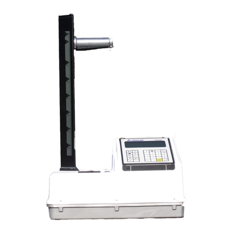
Troxler 3440-L User manual

Manual of Operation and Instruction
Model 3440-L
Surface Moisture-Density Gauge
Troxler Electronic Laboratories, Inc.
3008 Cornwallis Rd. •P.O. Box 12057
Research Triangle Park, NC 27709
Phone: 1.877.TROXLER
Outside the USA: +1.919.549.8661
Fax: +1.919.549.0761
www.troxlerlabs.com

ii
Troxler products are protected by U.S. and foreign patents.
Copyright ©2007
Troxler Electronic Laboratories, Inc.
All Rights Reserved
No part of this manual may be reproduced or transmitted in any form or by
any means, electronic or mechanical, including photocopying, recording,
or information storage and retrieval systems, for any purpose without the
express written permission of Troxler Electronic Laboratories, Inc.
Adobe and Acrobat are trademarks of Adobe Systems Incorporated, and are
registered in certain jurisdictions.
Fantastic is a trademark of Dow Consumer Products, Inc.
409 is a trademark of the Clorox Company.
Magnalube-G is a registered trademark of Carleton-Stuart Corporation.
Microsoft, Excel, Windows, and Word are registered trademarks of
Microsoft Corporation.
PN 111001
June 2007
Revision A

Model 3440-L iii
TROXLER SERVICE CENTERS
Troxler Corporate Headquarters
3008 Cornwallis Road
P.O. Box 12057
Research Triangle Park, NC 27709
Phone: 1.877.TROXLER (1.877.876.9537)
Outside the U.S.A.: +1.919.549.8661
Fax: +1.919.549.0761
Web: www.troxlerlabs.com
Technical Support
Phone: 1.877.TROXLER (1.877.876.9537)
Midwestern Branch Office
1430 Brook Drive
Downers Grove, IL 60515
Fax: 630.261.9341
Western Regional Branch Office
11300 Sanders Drive, Suite 7
Rancho Cordova, CA 95742
Fax: 916.631.0541
Southwestern Branch Office
2016 East Randol Mill Road
Suite 406
Arlington, TX 76011
Fax: 817.275.8562
Florida Service Center
2376 Forsyth Road
Orlando, FL 32807
Fax: 407.681.3188
Troxler European Subsidiary
Troxler Electronics GmbH
Gilchinger Strasse 33
D.82239 Alling nr. Munich, Germany
Phone: ++49.8141.71063
Fax: ++49.8141.80731
NOTE
To locate an independent, Troxler-authorized service center
near you, call 1.877.TROXLER (1.877.876.9537).

CAUTIONS AND WARNINGS
Units intended for use in countries that are members of the
European Community are shipped with a CE approved AC
adapter, Troxler bin number 108354.
Gauge cover is to be removed by trained service personnel
only. No user-serviceable components inside. Note:
Components behind cover can have voltage potentials in
excess of 50 volts during normal operation of the gauge.
Appendix C – Radiological Safety should be read carefully
and understood before using the gauge.
Alkaline Battery Use: See page F–3.
Safety Glasses: See page 3–2.
The source rod should automatically retract to the SAFE
position when the gauge is lifted.
See Scraper Ring/Tungsten Sliding Block Maintenance on
page F–5.
iv

Model 3440-L v
EU DECLARATION OF CONFORMITY
Application of Council EMC Directive 89/336/EEC and Low Voltage
Directive 73/23/EEC
Standards to which Conformity is Declared:
EN 61010-1
EN 55011 Group 1, Class A
EN 50082-2
An EMC Technical Report/Certificate has been issued in accordance
with Part IV (Reg 50) of the UK Regulations (SI 1992 No. 2372) by a UK
appointed Competent Body, namely,
Interference Technology International Limited
41-42 Shrivenham, Hundred Business Park
Shrivenham, Swindon, Wiltshire SN6 8TZ
Certificate Number C283TRO.1ABS Dated 16th January 1997
Troxler Document Number 108205
Manufacturer: Troxler Electronic Laboratories, Inc.
P.O. Box 12057
3008 Cornwallis Road
Research Triangle Park, North Carolina 27709
USA
Apparatus: Model 3440-L Surface Moisture-Density Gauge
Year of Declaration: 1997 (Original)
2006 (Corrected)

vi
NOTES

Model 3440-L vii
TABLE OF CONTENTS
CHAPTER 1. INTRODUCTION TO THE MODEL 3440-L
Introduction..............................................................................................1–2
Gauge and Accessories ............................................................................1–4
Control Panel Keypad..............................................................................1–6
CHAPTER 2. GETTING STARTED
Turning the Gauge On..............................................................................2–2
Basic Parameter Setup..............................................................................2–4
Taking the Standard Count.....................................................................2–13
CHAPTER 3. MEASUREMENT SITE PREPARATION
Soil and Base Course Preparation............................................................3–2
Asphalt Surface Preparation.....................................................................3–4
CHAPTER 4. TAKING A DENSITY/MOISTURE MEASUREMENT
Taking a Reading .....................................................................................4–2
Storing a Reading.....................................................................................4–4
CHAPTER 5. 3440-L OPERATIONS
Offsetting a Reading ................................................................................5–3
Count Time Function .............................................................................5–12
Store Function........................................................................................5–12
Proctor/Marshall/Voidless Function.......................................................5–13
Status Function.......................................................................................5–16
Mode Function.......................................................................................5–17
Project Function.....................................................................................5–17
Print Function.........................................................................................5–18
Erase Function........................................................................................5–21
Counts Function.....................................................................................5–21
Recall Function ......................................................................................5–22
Depth Function.......................................................................................5–22
Calculator Function................................................................................5–24
CHAPTER 6. SPECIAL FUNCTIONS
Stat Test....................................................................................................6–3
Drift Test..................................................................................................6–7
Recover Erase ..........................................................................................6–9
Keypad Data...........................................................................................6–10
Auto-Station...........................................................................................6–11
Special Calibration.................................................................................6–12
Nomograph.............................................................................................6–15
Precision.................................................................................................6–22
Set Units.................................................................................................6–24
Baud Rate...............................................................................................6–25

viii
TABLE OF CONTENTS (Continued)
CHAPTER 6. SPECIAL FUNCTIONS (Continued)
Communication Protocol .......................................................................6–26
Battery Monitor......................................................................................6–27
Source Decay.........................................................................................6–30
Special Roadway....................................................................................6–31
CHAPTER 7. EXTENDED FUNCTIONS
Time/Date ................................................................................................7–2
Customer Name .......................................................................................7–3
Serial Number..........................................................................................7–4
Calibration Date.......................................................................................7–5
Calibration Constants...............................................................................7–6
Rod Length...............................................................................................7–8
Erase Standard Counts.............................................................................7–9
Memory Clear........................................................................................7–10
Burn-In...................................................................................................7–10
Calibration Standard ..............................................................................7–11
Remote Control......................................................................................7–12
APPENDIX A. THEORY OF OPERATION
Density....................................................................................................A–2
Moisture..................................................................................................A–5
APPENDIX B. RADIATION THEORY
Atomic Structure.....................................................................................B–2
Radiation Theory ....................................................................................B–3
Radiation Statistics..................................................................................B–4
Radiation Terminology...........................................................................B–5
APPENDIX C. RADIOLOGICAL SAFETY
Radiation Types ......................................................................................C–2
Radiation Exposure.................................................................................C–3
Monitoring Radiation..............................................................................C–4
3440-L Radiation Profile ........................................................................C–4
Source Encapsulation..............................................................................C–6
Emergency Procedures............................................................................C–6
APPENDIX D. LICENSING REQUIREMENTS
Specific License......................................................................................D–2
Radiation Safety Program.......................................................................D–2
Personnel Monitoring..............................................................................D–2
Security...................................................................................................D–2
Training...................................................................................................D–3

Model 3440-L ix
TABLE OF CONTENTS (Continued)
APPENDIX D. LICENSING REQUIREMENTS (Continued)
Leak Test.................................................................................................D–3
Notice to Employees...............................................................................D–3
Incidents..................................................................................................D–3
Disposal...................................................................................................D–4
Record Keeping.......................................................................................D–4
APPENDIX E. TRANSPORTATION AND SHIPPING
U.S. Requirements ..................................................................................E–2
Canadian Shipping Requirements...........................................................E–4
APPENDIX F. PERIODIC MAINTENANCE AND SERVICE
Batteries .................................................................................................. F–2
Mechanical Maintenance......................................................................... F–4
Electronic Maintenance........................................................................... F–9
Replacement Parts................................................................................. F–16
Returning a Gauge for Service.............................................................. F–27
APPENDIX G. 3440-L SPECIFICATIONS
Measurement Specifications ...................................................................G–2
Calibration Specifications.......................................................................G–3
Radiological Specifications.....................................................................G–3
Memory Specifications ...........................................................................G–3
Electrical Specifications..........................................................................G–4
Mechanical Specifications.......................................................................G–5
APPENDIX H. LOG FORMS & COMPACTION TEST DATA
APPENDIX I. UNIT CONVERSION
Measurement Units ..................................................................................I–2
Radiological Units....................................................................................I–2
APPENDIX J. PRINTING (UPLOADING) PROJECT DATA
Windows Hyperterminal..........................................................................J–2
Viewing Project Data...............................................................................J–4
INDEX
WARRANTY

x
LIST OF FIGURES
Figure Title Page
1–1 3440-L Gauge and Standard Accessories.............................. 1–5
1–2 3440-L Keypad Layout ......................................................... 1–7
2–1 3440-L Gauge Showing Rod Positions............................... 2–14
2–2 Gauge Position on Reference Standard Block..................... 2–15
3–1 Drill Rod and Extraction Tool with Scraper Plate................. 3–2
3–2 Marking the Test Area ..........................................................3–3
5–1 Gauge and Reference Standard Block Position
for Trench Offset................................................................. 5–11
5–2 Serial Port Location............................................................. 5–18
5–3 Sample Project Printouts..................................................... 5–20
5–4 Calculator Function Keys.................................................... 5–24
6–1 Stat Test Printout Sample...................................................... 6–6
6–2 Drift Test Printout Sample.................................................... 6–8
A–1 Direct Transmission Geometry ............................................ A–2
A–2 Backscatter Geometry.......................................................... A–3
A–3 Depth of Top Layer.............................................................. A–4
A–4 Effect of Moisture on Depth of Measurement...................... A–7
B–1 Diagram of an Atom..............................................................B–2
B–2 Variation of Radioactive Emission........................................B–4
C–1 Effect of Distance on Exposure.............................................C–3
C–2 3440-L Gauge and Transport Case........................................C–4
D–1 Sample Notice to Employees............................................... D–6

Model 3440-L xi
LIST OF FIGURES (Continued)
Figure Title Page
F–1 Retaining and Scraper Rings.................................................F–5
F–2 3440-L Baseboard Assembly ................................................F–9
F–3 3440-L Gauge Assembly (Sheet 1 of 2)..............................F–16
F–4 3440-L Base Mechanical Assembly....................................F–20
F–5 3440-L Source Rod Handle Assembly................................F–20
F–6 3440-L Preamplifier Assembly ...........................................F–22
F–7 3440-L Front Panel Assembly.............................................F–24

xii
LIST OF TABLES
Table Title Page
1–1 3440-L Keypad Functions..................................................... 1–8
A–1 Neutron Thermalization and Absorption Data..................... A–6
C–1 Radiation Dose Equivalent Rates in Millirems per Hours ....C–5
F–1 3440-L Gauge Assembly Parts............................................F–18
F–2 3440-L Base Mechanical Assembly Parts...........................F–21
F–3 3440-L Source Rod Handle Assembly Parts.......................F–21
F–4 3440-L Preamplifier Assembly Parts..................................F–23
F–5 3440-L Front Panel Assembly Parts....................................F–25

Model 3440-L xiii
ATTENTION GAUGE OWNER
This gauge contains functions that require an ACCESS
CODE. This code must be entered before these functions may
be used. For more information on using the access code, refer
to the specific function in Chapter 7.
The ACCESS CODE for this gauge is:
4688 (Denmark only 2037)
This page should be removed if the access code is not to be
distributed to other parties or users of this gauge.

xiv
NOTES

Model 3440-L 1–1
1. INTRODUCTION
CHAPTER 1
INTRODUCTION TO THE MODEL 3440-L
This chapter will familiarize the operator with the features and capabilities
of the Troxler Model 3440-L Surface Moisture-Density Gauge. A brief
introduction to the system, as well as illustrations of the important
components of the system, are included. Taking time to review this chapter
before beginning operation of the system will help the operator to gain a
more complete understanding of system operations.
CONTENTS
Introduction..............................................................................................1–2
Gauge and Accessories ............................................................................1–4
Control Panel Keypad..............................................................................1–6

INTRODUCTION
The Troxler Model 3440-L Surface Moisture-Density Gauge measures the
moisture content, density, and compaction of soils, soil-stone aggregates,
concrete, asphalt treated bases, asphalt surfacing, and other materials that
approximate similar ranges of density and/or moisture content. The latest
engineering, design, and manufacturing techniques have been incorporated
into the 3440-L gauge, as well as over thirty years of experience in the
nuclear gauge industry.
The versatile 3440-L gauge uses two modes of operation (backscatter and
direct transmission) and can store over 450 readings. The gauge also
provides over 30 special functions and operator-selectable precision for all
phases of construction material testing. The LCD display and easy-to-use
keypad ensure the operator of fast, accurate test measurement results.
This manual contains sections that cover basic gauge setup and operation,
as well as advanced operating techniques. The appendices provide
information on radiation theory and radiation safety. Each chapter contains
a table of contents for quickly locating the function required. If a question
arises about the gauge, gauge operation, or an application not covered by
this manual, please contact the closest Troxler Sales/Service Center or your
Troxler Representative.
Changes and additions may be made to the 3440-L gauge and this manual
without notice. Acquire updated information or a newer version of this
manual by contacting the Troxler Sales Department or a Troxler
Representative. The current edition of the manual can also be downloaded
and/or viewed (using Adobe®Acrobat®Reader) from the Troxler
website, www.troxlerlabs.com.
NOTE
While no radiation hazard is imposed on operator(s)
during normal use, a potential hazard does exist if
improperly used. The sections of the manual covering
radiological safety should be required reading for all
operators and potential operators. If these sections are
not completely understood, operators should seek
assistance from Troxler, an appointed Troxler
representative or others designated within the operator
organization.
1–2

As changes are made to government regulations on a continuing basis, the
owner/operator must maintain a knowledge of these regulations. The
responsibility for compliance ultimately falls upon the owner.
1. INTRODUCTION
NOTE
Any licensing issues discussed in this manual are for the
United States. International communities should follow
local regulations regarding products utilizing radioactive
materials.
Model 3440-L 1–3

1–4
GAUGE AND ACCESSORIES
The Troxler 3440-L gauge provides a fast, accurate, and inexpensive way
to find the moisture content and density of construction type materials.
Take a moment to become familiar with the features and controls of the
3440-L, its components, operating principles, safeguards and cautions. Use
Figure 1–1 and the list below to identify the gauge and standard
accessories as they are unpacked.
1. The GAUGE is the portable surface moisture-density gauge
containing the radioactive sources, electronics and rechargeable
battery packs. The gauge serial number appears on the gauge handle
and the reference standard block, as well as on the calibration, source,
and warranty certificates.
2. The REFERENCE STANDARD BLOCK is primarily used to
establish standard counts against which future measurements are
compared. The reference standard block is also an unchanging
reference for long-term stability checks.
3. The SCRAPER PLATE/DRILL ROD GUIDE is used to prepare the
test site. It is used to guide the drill rod in preparing a hole for the
source rod for direct transmission measurements.
4. The DRILL ROD is used to drill a hole for direct transmission
measurements. Under no circumstances should the source rod be
used for this purpose.
5. The DRILL ROD EXTRACTION TOOL provides leverage to
remove the drill rod from clays and other materials.
6. Two CHARGER/ADAPTERS are supplied: one for dc (12 volt
negative ground systems) and one for ac.
7. The TRANSPORT CASE is specially fitted for safe transport of the
3440-L and associated parts. The case is water-resistant, but is not
watertight. In case of inclement weather, the case should be protected
with some type of covering to prevent intrusion of rain, etc.
8. OPERATOR’S MANUAL, CALIBRATION DOCUMENTS, and
GAUGE CERTIFICATE

TRANSPORT CASE
GAUGE
AC CHARGER
DC ADAPTER
SCRAPER PLATE/
DRILL ROD GUIDE
DRILL
ROD
EXTRACTION
TOOL
REFERENCE
BLOCK
GAUGE CERTIFICATE
& WARRANTY
OPERATOR'S MANUAL W/
Q
UICK REFERENCE GUIDE
1. INTRODUCTION
Figure 1–1. 3440-L Gauge and Standard Accessories
Model 3440-L 1–5

1–6
CONTROL PANEL KEYPAD
The 3440-L gauge control panel consists of two sections: the 20-key
control keypad (Figure 1–2) and the 〈ON〉and 〈OFF〉keys. Keystrokes
result in an immediate “beep” from the gauge. If the beep is not heard, the
operation is not completed. Gauge and control panel operations are
described throughout the manual. Table 1–1 summarizes the functions of
each key, and provides page references for more information on certain
operations.
The 〈SHIFT〉and shift function keys are color-coded yellow for ease of
identification. The 〈SHIFT〉must be pressed before pressing a function
key. Functions are directly addressable from any other function except the
calculator mode. Pressing 〈SHIFT〉causes the display’s top line to change
to –SHIFT FUNCTION–.
NOTE
If a function key is not pressed within four seconds, the gauge
reacts as if no key was pressed. If there is no action after
pressing a key, the gauge will return to READY after two
minutes.
The 〈YES〉, 〈NO/CE〉, and 〈START/ENTER〉keys apply to all gauge
modes. For a complete reference to any function, consult the index.
Pressing 〈START/ENTER〉from most modes will abort the mode and
begin a test.
The calculator function keys are 〈MS〉, 〈MR〉, 〈+〉, 〈–〉, 〈×〉, 〈÷〉, and 〈=〉.
This manual suits for next models
1
Table of contents
Other Troxler Measuring Instrument manuals
Troxler
Troxler 3430 Plus User manual

Troxler
Troxler RoadReader 3430 Guide
Troxler
Troxler RoadReader Plus 3450 User manual
Troxler
Troxler RoadReader 3430 User manual
Troxler
Troxler 3400-B Series User manual

Troxler
Troxler Enhanced RoadReader Plus 3451 User manual

Troxler
Troxler EGauge 4590 User manual

Troxler
Troxler 3241 Series User manual
Troxler
Troxler 4640-B Guide

Troxler
Troxler RoadReader 3430 User manual
