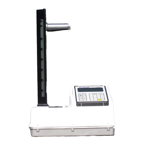
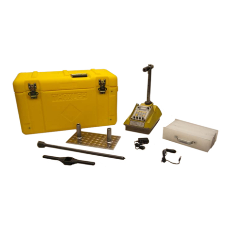
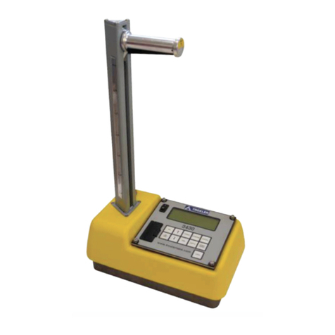
Troxler EGauge 4590 User manual

Manual of Operation and Instruction
E
EG
Ga
au
ug
ge
e™
™
M
Mo
od
de
el
l 4
45
59
90
0
S
So
oi
il
l D
De
en
ns
si
it
ty
y G
Ga
au
ug
ge
e
Troxler Electronic Laboratories, Inc.
3008 Cornwallis Rd. •P.O. Box 12057
Research Triangle Park, NC 27709
Phone: 1.877.TROXLER
Outside the USA: +1.919.549.8661
Fax: +1.919.549.0761
www.troxlerlabs.com

ii
Troxler products are protected by U.S. and foreign Patents
Copyright 2020
Troxler Electronic Laboratories,
Inc. All Rights Reserved
No part of this manual may be reproduced or transmitted in
any form or by any means, electronic or mechanical,
including photocopying, recording, or information storage
and retrieval systems, for any purpose without the express
written permission of Troxler Electronic Laboratories, Inc.
Magnalube-G is a registered trademark of Magnalube, Inc.
BindOff is a registered trademark of Chemical Solutions, Inc.
Doc UM-4590
PN 128990
October 2020
Edition 3.3

Model 4590
iii
SAFETY ALERT SYMBOL
The Safety Alert Symbol shall appear within this manual. Wherever it
appears in this manual or on safety signs affixed to the machine, this is
to make all aware of the potential for personal injury and to be cautious
when these images are present.
Always observe all WARNING, CAUTION, and NOTE recommendations
listed within this manual before operating the machine.

iv
TROXLER SERVICE CENTERS
Troxler Corporate Headquarters (North Carolina)
3008 E. Cornwallis Road
Research Triangle Park, NC 27709
1-877-TROXLER (1-877-876-9537)
1-919-549-8661
www.troxlerlabs.com
Technical Support
1-877-TROXLER (1-877-876-9537)
+1-919-549-8661
troxtechsupport@troxlerlabs.com
Minnesota
9835 13th Avenue North
Plymouth, MN 55441
1-763-600-6540
testquip@troxlerlabs.com
California (Northern)
11300 Sanders Drive, Ste. 7
Rancho Cordova, CA 95742
1-916-631-0234
troxlerca@troxlerlabs.com
Louisiana
12180 Greenwell Springs Road
Baton Rouge, LA 70814
1-225-218-4703
troxlerla@troxlerlabs.com
California (Southern)
701 South Gifford Avenue, Ste. 101
San Bernardino, CA 92408
1-909-890-1069
troxlerca@troxlerlabs.com
Texas (Dallas Area)
2016 E. Randol Mill Road, Ste. 406
Arlington, TX 76011
1-817-275-0571
troxlertx@troxlerlabs.com
Florida (Orlando)
531 Holts Lake Court
Orlando, FL 32703
1-407-681-4221
troxlerfl@troxlerlabs.com
Texas (Houston Area)
25000 Central Parkway, Ste. L
Houston, TX 77092
1-832-519-9343
troxlerhouston@troxlerlabs.com
Florida (Fort Myers)
1681 Benchmark Avenue, Ste. 100
Fort Myers, FL 33905
1-239-215-1146
troxlerfl@troxlerlabs.com
Illinois
1430 Brook Drive
Downers Grove, IL 60515
1-630-261-9304
troxleril@troxlerlabs.com
Troxler Electronic Technologies
Zhangjiagang (ZJG)
West No. 1
North 2nd Ring
Jiangsu, China 615200
Ohio
6969 Worthington Galena Rd, Suite C,
Columbus, OH 43085
troxleroh@troxlerlabs.com
Troxler Europe & Service Center
Troxler Electronics GmbH
Waldstrasse 4, D. 82239 Alling nr.
Munich, Germany
Phone: ++ 49.8141.71063
Fax: ++49.8141.80731
troxler@t-online.de
NOTE
To locate an independent, Troxler-authorized service partner near you,
call 1-877-TROXLER.

Model 4590
v
ABOUT THIS MANUAL
The Model 4590 Manual of Operation and Instruction provides
detailed information about this gauge. The manual includes
product safety information, as well as instructions for the
proper installation and use of the Model 4590 gauge.
This manual is organized as follows:
Chapter 1, Introduction – Provides information on the safe use
of the gauge; a brief overview of the unit and its features; a list
of parts and accessories; and instructions for unpacking and
inspection.
Chapter 2, Theory of Operation – Provides a brief description
of how the gauge’s operations work in relation to their sources.
Chapter 3, Gauge Setup – Describes the keypad and provides
instructions for setting up, starting, and operating the gauge.
Chapter 4, Using the Gauge – Describes taking a standard
count, preparing the test site, and taking measurements.
Chapter 5, Setup Menu – Describes the options available from
the Setup menu.
Chapter 6, Target Menu – Describes the options available from
the Target menu.
Chapter 7, Calibration Offsets – Provides procedures for
taking density, moisture, and trench offsets.
Chapter 8, Project Data – Describes the options available from
the Project menu.
Chapter 9, Extended Menu – Describes the options available
from the Extended menu.

vi
Appendix A, Maintenance & Troubleshooting – Provides
maintenance and service information, as well as instructions for
basic troubleshooting.
Appendix B, Specifications – Contains mechanical, electrical,
and environmental performance specifications.
Appendix C, Transporting and Shipping – Provides
information about shipping requirements for the United States
and Canada.
Appendix D, Radiation Safety & Theory – Provides a radiation
primer, regulatory requirements, and gauge safety precautions.
Appendix E, Unit Conversion – Provides conversions for
measurement and radiological units.
Appendix F, Standard Count Log – Use this form to record
your standard count readings.
Appendix G, Global Positioning System (GPS) – Describes the
accuracy of the optional GPS feature.

Model 4590
vii
HOW TO USE THIS MANUAL
Congratulations on the purchase of the Troxler Model 4590
Surface Density Gauge.
The Model 4590 Manual of Operation and Instruction contains
information on how the Model 4590 operates and provides
directions on the use of this gauge. Site selection, basic
parameter setup, moisture and density determination, data
storage, and advanced operations are included, along with
radiological information and system troubleshooting.

vii
WARNING
Warnings indicate conditions or procedures that,
if not followed correctly, may cause personal
injury.
CAUTION
Cautions indicate conditions or procedures that, if not
followed correctly, may cause equipment damage.
DISPLAY–Typestyle and
shading used to simulate
the control panel display
CONVENTIONS USED IN THIS MANUAL
Throughout this manual the following symbols and special
formatting are used to reveal the purpose of the text.
NOTE
Notes indicate important information that must be
read to ensure proper operation.
〈KEY〉This style indicates a key or character to press on the
gauge keypad.
1
1.
. Indicates a procedure with multiple steps.
♦Indicates a list of things needed (such as equipment)or
important points to know.
♦Indicates that more than one option is available. Carefully
select the option that applies.


viii
CAUTIONS AND WARNINGS
When not taking measurements, always keep the source
rod in the SAFE position. For added operator safety, the
source rod on the gauge retracts to the SAFE position
when the gauge is picked up by the handle.
Do not store or transport the gauge unless the handle is
raised to the safe position and locked. Increased radiation
levels may violate transportation regulations and cause
excessive personnel exposure.
Units intended for use in countries that are members of
the European Community are shipped with an AC adapter,
Troxler part number 108354.
Gauge cover is to be removed by trained service
personnel only. There are no user-serviceable
components inside. Note that components behind the
cover can have voltage potentials in excess of 50 volts
during normal operation of the gauge.
Appendix D, Radiation Theory and Safety should be read
carefully and understood before using the gauge.
The Model 4590 gauges are not waterproof. Do not use
them in the rain. If the gauge gets wet, make sure it is
completely dry before sealing it in the case for storage.
Even small amounts of moisture can get into the body of
the gauge and cause damage. See Troubleshooting on
page-A-2 for more information.

Model 4590
ix
TABLE OF CONTENTS
CHAPTER 1: INTRODUCTION .......................................
1–1
Introduction .............................................................................................. 1–2
Regulations and Licensing.................................................................... 1–4
Gauge Parts and Accessories............................................................... 1–5
Unpacking and Inspection.................................................................... 1–7
CHAPTER 2: THEORY OF OPERATION...........................2–1
Mode of Operation................................................................................. 2–2
Moisture Measurements ....................................................................... 2–3
Calibration................................................................................................. 2–4
Offsets ........................................................................................................ 2–5
CHAPTER 3: PREPARING FOR USE ..................................3–1
Gauge Illustration.................................................................................... 3–2
Control Panel............................................................................................ 3–3
Source Rod Positions ............................................................................. 3–5
Charging the Gauge............................................................................... 3–6
Turning the Gauge On .......................................................................... 3–7
Daily Inspection ....................................................................................... 3–9
Selecting Measurement Options ......................................................3–10
CHAPTER 4: USING THE GAUGE......................................4–1
Site Preparation ....................................................................................... 4–2
Taking the Standard Count .................................................................. 4–5
Taking Measurements..........................................................................4–13
Recall ........................................................................................................4–20
CHAPTER 5: SETUP MENU.................................................5–1

x
Setup Menu .............................................................................................. 5–2
Count Time ............................................................................................... 5–3
BGD Count Time ..................................................................................... 5–4
Set Units..................................................................................................... 5–5
Depth Mode ............................................................................................. 5–6
Options ...................................................................................................... 5–7
Battery Status .........................................................................................5–12
Percent Air Voids...................................................................................5–13
Moisture Probe ......................................................................................5–15
Stat Test ...................................................................................................5–18
Drift Test .................................................................................................. 5–20
CHAPTER 6: TARGET MENU.............................................. 6–1
Target Menu............................................................................................. 6–2
CHAPTER 7: CALIBRATION OFFSETS.............................. 7–1
About Offsets ........................................................................................... 7–2
Density Offset........................................................................................... 7–4
Trench Offset............................................................................................ 7–6
Moisture Probe Offset ........................................................................... 7–7
CHAPTER 8: PROJECT DATA.............................................8–1
Project Menu ............................................................................................ 8–2
Select a Project ........................................................................................ 8–3
View Project Data.................................................................................... 8–4
Create a Project....................................................................................... 8–5
Erase Projects ........................................................................................... 8–6
Output Project ......................................................................................... 8–7

Model 4590
xi
Set Output Destination.......................................................................... 8–9
Deactivate a Project..............................................................................8–11
Auto-Store ..............................................................................................8–12
Manual Store ..........................................................................................8–14
CHAPTER 9: EXTENDED MENU ........................................9–1
Extended Menu........................................................................................ 9–2
Clock/Calendar ........................................................................................ 9–3
Source Decay ........................................................................................... 9–7
Erase Standard Counts .......................................................................... 9–8
Low Battery Warning.............................................................................. 9–9
Software Reset .......................................................................................9–10
Show Calibration Constants ...............................................................9–11
Test Menu................................................................................................9–12
APPENDIX A: MAINTENANCE & TROUBLESHOOTINGA-1
Troubleshooting...................................................................................... A-2
Batteries .....................................................................................................A-9
Mechanical Maintenance....................................................................A-12
Replacement Parts................................................................................A-14
Returning the Gauge for Service......................................................A-16
APPENDIX B: SPECIFICATIONS.................................. B-1
Measurement Specifications.................................................................B-2
Radiological Specifications....................................................................B-3
Electrical Specifications...........................................................................B-4
Mechanical Specifications......................................................................B-5

xii
APPENDIX C: TRANSPORTING & SHIPPING................... C-1
U.S. Shipping Requirements.................................................................C-2
Accident Notification Requirements .................................................. C-4
APPENDIX D: RADIATION THEORY & SAFETY............D-1
Radiological Information.......................................................................D-2
Leak Testing..............................................................................................D-4
Training......................................................................................................D-5
Disposal...................................................................................................... D-6
Emergency Procedures .........................................................................D-7
Gauge Use Precautions.........................................................................D-9
APPENDIX E: UNIT CONVERSION..............................E-1
Measurement Units .................................................................................E-3
APPENDIX F: STANDARD COUNT LOG ...........F-1
Standard Count Log................................................................................F-2
Moisture Probe Offset Worksheet.......................................................F-4
APPENDIX G: GLOBAL POSITIONING SYSTEM (GPS)..G-1
GPS Accuracy...........................................................................................G-2
INDEX
WARRANTY

Model 4590
xiii
LIST OF FIGURES
Figure 1. 4590 Gauge and Standard Accessories........................... 1–6
Figure 2. Model 4590 Gauge Components ..................................... 3–2
Figure 3. Model 4590 Control Panel.................................................. 3–3
Figure 4. Source Rod Positions............................................................ 3–5
Figure 5. Drill Rod Positioning ............................................................. 4–3
Figure 6. Marking the Test Area.......................................................... 4–4
Figure 7. Gauge Position on Soil......................................................... 4–9

xiv
LIST OF TABLES
Table 1. Model 4590 Keypad Functions............................................ 3–4
Table 2. Spreadsheet Column Definitions ........................................ 8–8
Table 3. Error Messages........................................................................A-6
Table 4. Typical Battery Operating Life.............................................A-9
Table 5. GPS Position Accuracy ..........................................................G-4

Model 4590
xv
ATTENTION MODEL 4590 GAUGE OWNER
This unit contains functions that require an Access Code
to be entered. This allows some control over the access
to these functions. If you would like management to
retain this control, remove this page upon receipt of the
gauge and file it somewhere safe.
THE ACCESS CODE IS FOR THIS GAUGE IS:
5838

xvi
NOTES

Model 4590
1-1
C
Ch
ha
ap
pt
te
er
r 1
1:
:
I
In
nt
tr
ro
od
du
uc
ct
ti
io
on
n
This chapter covers the following topics and tasks:
An introduction to your new Model 4590 gauge
Inspecting and unpacking
Included parts and accessories

1–2
I
In
nt
tr
ro
od
du
uc
ct
ti
io
on
n
The Model 4590 Surface Density Gauge uses the latest
engineering, design, and manufacturing techniques. This gauge
uses a gamma-ray transmission method of measuring the
specific gravity and density of soil and soil aggregate bases.
When the moisture content of the material is known, the gauge
can determine the dry density.
The density measurement method used in the Model 4590 is
based on the scattering and absorption properties of gamma
rays with matter. This gauge uses a 3.3 MBq (90-μCi) cesium-
137 (Cs-137) gamma-ray source and a sodium iodide (NaI)
scintillation gamma ray detector. The gamma ray source is
securely placed at one end of the source rod. The detector is
located inside the gauge housing.
The gamma-ray method also known as the nuclear method of
measuring density of soil and soil-aggregate bases has been
approved by the American Society of Testing and Materials
(ASTM). The Model 4590 gauge complies with ASTM D8167,
Standard Test Method for In-Place Bulk Density of Soil and
Soil-Aggregate by a Low-Activity Nuclear Method (Shallow
Depth).
NOTE
This gauge does not have a backscatter mode;
therefore, it cannot be used on asphalt pavements.
Using the Model 4590 gauge, you can precisely measure
the moisture content and density of construction
materials. The gauge features:
♦Over 30 functions to facilitate all phases of testing
compaction on construction materials.
♦A backlit LCD screen to help you read the display during
night construction.
♦Easy-to-use keypad and user-friendly menus to reduce
training time to increase productivity.
♦A remote keypad, including a 〈START〉and 〈ESC〉key, at
the top of its source rod housing. These keys perform the
same function as the keys on the control panel.
Other manuals for EGauge 4590
1
Table of contents
Other Troxler Measuring Instrument manuals

Troxler
Troxler TroxAlert User manual
Troxler
Troxler RoadReader 3430 User manual
Troxler
Troxler 4640-B Guide

Troxler
Troxler 3216 User manual
Troxler
Troxler 3430 Plus User manual

Troxler
Troxler Enhanced RoadReader Plus 3451 User manual
Troxler
Troxler RoadReader Plus 3450 User manual
Troxler
Troxler PaveTracker Plus User manual

Troxler
Troxler 3241 Series User manual
Troxler
Troxler 3440-L User manual


