Wet Labs ECO VSF User manual

ECO VSF User’s Guide (VSF) Revision AN 14 Sept. 2011
ECO VSF
Volume Scattering Function Meter
User’s Guide
The user’s guide is an evolving document. If you find sections that are unclear, or
missing information, please let us know. Check our website periodically for updates.
WET Labs, Inc.
P.O. Box 518
Philomath, OR 97370
541-929-5650
fax: 541-929-5277
www.wetlabs.com


ECO VSF User’s Guide (VSF) Revision AN 14 Sept. 2011
ECO Sensor Warranty
This unit is guaranteed against defects in materials and workmanship for one year from
the original date of purchase. Warranty is void if the factory determines the unit was
subjected to abuse or neglect beyond the normal wear and tear of field deployment, or in
the event the pressure housing has been opened by the customer.
To return the instrument, contact WET Labs for a Return Merchandise Authorization
(RMA) and ship in the original container. WET Labs is not responsible for damage to
instruments during the return shipment to the factory. WET Labs will supply all
replacement parts and labor and pay for return via 3rd day air shipping in honoring this
warranty.
Shipping Requirements
1. Please retain the original shipping material. We design the shipping container to meet
stringent shipping and insurance requirements, and to keep your meter functional.
2. Clearly mark the RMA number on the outside of your shipping container and on all
packing lists.
3. Return instruments using 3rd day air shipping or better: do not ship via ground.
Return Policy for Instruments with
Anti-fouling Treatment
WET Labs cannot accept instruments for servicing or repair that are treated with anti-
fouling compound(s). This includes but is not limited to tri-butyl tin (TBT), marine anti-
fouling paint, ablative coatings, etc.
Please ensure any anti-fouling treatment has been removed prior to returning instruments
to WET Labs for service or repair.
Electrical equipment marked with this symbol may not be disposed
of in European public disposal systems. In conformity with EU
Directive 2002/96/EC (as amended by 2003/108/EC), European
users of electrical equipment must return old or end-of-life
equipment to the manufacturer for disposal at no charge to the user.


ECO VSF User’s Guide (VSF) Revision AN 14 Sept. 2011 i
Table of Contents
1. Specifications ................................................................................................................ 1
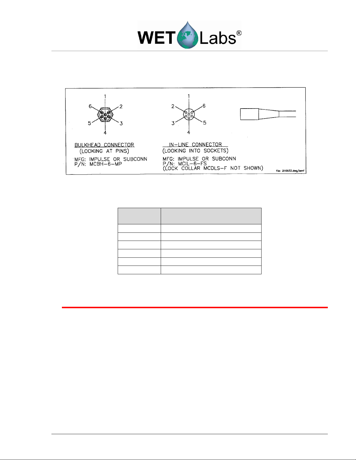
1.1 Connectors ........................................................................................................................ 2
1.2 Delivered Items .................................................................................................................. 3
1.3 Optional Equipment ........................................................................................................... 4
2. Theory of Operation ...................................................................................................... 6
3. Instrument Operation .................................................................................................... 7
3.1 Initial Checkout .................................................................................................................. 7
3.2 Operating the Sensor for Data Output ................................................................................ 7
3.3 Bio-wiper™ Operation ........................................................................................................ 8
3.4 Deployment ....................................................................................................................... 8
3.5 Upkeep and Maintenance .................................................................................................. 9
4. VSFB and VSFSB: Using Internal Batteries ................................................................. 12
4.1 Removing End Flange and Batteries .................................................................................. 12
4.2 Replacing End Flange and Batteries .................................................................................. 13
4.3 Checking Vent Plug, Changing O-Rings: ............................................................................ 14
5. Data Analysis ................................................................................................................. 15
5.1 Data Corrections ................................................................................................................ 15
5.2 Determining other Angle-Specific Coefficients .................................................................... 16
6. Testing and Calibration ................................................................................................. 17
6.1 Testing............................................................................................................................... 17
6.2 Calibration ......................................................................................................................... 17
7. General Terminal Communications ............................................................................. 20
7.1 Communication Settings ..................................................................................................... 20
7.2 ECO Command List and Data Format ................................................................................ 20
8. Device and Output Files ................................................................................................ 21
8.1 Plot Header........................................................................................................................ 21
8.2 Column Count Specification ............................................................................................... 21
8.3 Column Description ............................................................................................................ 21
8.4 Sample Device File ............................................................................................................ 22
8.5 Sample Output File ............................................................................................................ 22
Appendix A: Mounting Bracket Drawing ........................................................................ 23


ECO VSF User’s Guide (VSF) Revision AN 14 Sept. 2011 1
1. Specifications
Model
VSF(RT)
VSF
VSFS
VSFB
VSFSB
Mechanical
Diameter 6.3 cm
Length 12.7 cm 13.3 cm 27.4 cm 27.99 cm
Weight, in air 0.4 kg 0.5 kg 0.96 kg
Material Acetal copolymer
Environmental
Temperature range 0–30 deg C
Depth rating 600 m 300 m
Optional pressure sensor -- Y
Optional thermistor -- Y
Electrical
Output resolution 12 bit
Internal data logging N Y
Internal batter
ies
N Y Y
Connector MCBH6MP
Input
7–15 VDC
Current, typical 60 mA
Current, sleep 140 µA
Data memory -- 77,000 samples
Sample rate to 8 Hz
RS
-
232 output
19200 baud
Optional Anti
-
fouling
bio-wiper™ N Y N Y
Bio-wiper™ cycle - - 140 mA
Optical
Wavelength 470, 532, or 650 nm
Sensitivity 0.003 m-1
Range, typical 0–5 m
-
1
Linearity 99% R2
VSF(RT)—Provides an RS-232 serial output with 4000-count range. This unit can be programmed for
continuous operation.
VSF—Provides an RS-232 serial output with 4000-count range. This unit can be programmed for
continuous operation or periodic sampling.
VSFS—Provides the capabilities of the VSF with an integrated anti-fouling Bio-wiper™.
VSFB—Provides the capabilities of the VSF and self-recording with internal batteries for autonomous
operation.
VSFSB—Provides the capabilities of the VSF with an integrated anti-fouling Bio-wiper™ and self-recording
with internal batteries for autonomous operation.
Specifications subject to change without notice.

2 ECO VSF User’s Guide (VSF) Revision AN 14 Sept. 2011
1.1 Connectors
ECO VSF meters use a six-pin bulkhead connector. The pin functions for this connector are
shown in Figure 1. Table 1 summarizes pin functions for the bulkhead connectors.
Figure 1. ECO VSF connector schematic
Table 1. Pinout summary for ECO connectors
Pin
(or Socket)
Function
1 Ground
2 RS-232 (RX)
3 Reserved
4 V In
5 RS-232 (TX)
6 Configurable
WARNING
If you are going to build or use a non-WET Labs-built cable, do not use the wire
from pin 3 or the ECO meter will be damaged.
Input power of 7–15 volts DC is applied to pin 4. The power supply current returns through
the common ground pin. The input power signal has a bi-directional filter. This prevents
external power supply noise from entering into the ECO VSF, and also prevents internally
generated noise from coupling out on to the external power supply wire. Data is sent out pin
5.
1.1.1 ECO VSFB and VSFSB Connectors
ECO VSFB and VSFSB (units with internal batteries) have an second bulkhead connector
that comes with a jumper plug to supply power to the unit. The pin functions for this
connector are shown in Figure 2. Table 2 summarizes pin functions for the 3-socket
bulkhead connector.

ECO VSF User’s Guide (VSF) Revision AN 14 Sept. 2011 3
Figure 2. ECO VSFB and VSFSB connector schematic
Table 2. Pinout summary for ECO 3-socket connector
Pin (or Socket) Function
1 V in
2 N/C
3 Battery out
1.2 Delivered Items
The standard VSF delivery consists of the following:
the instrument itself
protective cover for optics
dummy plug with lock collar
this user’s guide
ECOView user’s guide
ECOView host program and device file (on CD)
instrument-specific calibration sheet
VSF(RT), VSF, VSFS: stainless steel mounting bracket and hardware (See Appendix A
for details)
One 3/32-in. hex key for bio-wiper™ removal
Three 4-40 x 3/8 in. 316 stainless steel replacement screws for bio-wiper™
Internal battery units: six 9-V Lithium batteries (installed)
spare parts kit (battery units only):
Two end flange O-rings (size 224)
Two vent plug O-rings (size 010)
Two jacking screws for connector flange removal
One 3/32-in. hex key for jacking screws
Power plug for autonomous operation
Three pre-cut segments (7 inches) of 0.036-inch diameter monofilament for end flange
Three pre-cut segments (0.25 inches) of 0.094-inch diameter white nylon bar stock for
replacing the white plastic dowel pin

4 ECO VSF User’s Guide (VSF) Revision AN 14 Sept. 2011
1.3 Optional Equipment
1.3.1 Test Cable
A test cable is supplied with each unit. This cable includes three legs:
1. A connector for providing power to the instrument from a user-supplied 9V battery.
2. A DB-9 serial interface connector.
3. A six-socket in-line connector for providing power and signal to the instrument.
1.3.2 Copper Faceplate
ECO meters are optionally equipped with copper faceplates to improve the meter’s
resistance to biofouling. Refer to Section 3.5.1 for important details on maintenance and
cleaning.
1.3.3 Bio-wiper™ and Copper Faceplate
The BBS and BBBS are equipped with an integrated non-contact anti-fouling bio-wiper™
and copper faceplate for use in extended deployments. This wiper can be manually
controlled by a host controller package, or can perform autonomously as part of a pre-
programmed sampling sequence upon instrument power-up. The rate of opening and closing
depends on both temperature and depth.
Refer to Section 3.5.1 for important details on the maintenance and cleaning of the Bio-
wiper™ and copper faceplate.
WARNING!
Do NOT rotate the Bio-wiper™ manually. This can damage the wiper motor and will void
the warranty.
1.3.4 Batteries
ECO units with internal batteries are supplied with six 9-volt Lithium batteries as their
power source. They can use either standard alkaline cells for a total capacity of
approximately 1000 mA-hrs, or for longer deployments, LiMnO2 cells to achieve more
than 2000 mA-hrs of operational capacity. Actual total usage time of the internal batteries
is a function of several parameters. These include nominal water temperature, sequence
timing, sample periods, and total deployment duration.
1.3.5 External Thermistor
ECO meters are optionally equipped with an external thermistor. The thermistor is
calibrated at WET Labs and the calibration coefficients are supplied on the instrument’s
calibration sheets. Thermistor output is in counts and can be converted into engineering
units using the instrument’s device file and ECOView software or the raw data can be
converted in the user’s software (e.g. MATLAB or Excel) using the calibration equation:
Temperature (deg C) = (Output * Slope) + Intercept
1.3.6 Pressure Sensor
ECO meters are optionally equipped with a strain gauge pressure sensor. The pressure
sensor is calibrated at WET Labs and the calibration coefficients are supplied on the

ECO VSF User’s Guide (VSF) Revision AN 14 Sept. 2011 5
instrument’s calibration sheets. Pressure sensor output is in counts and can be converted
into engineering units using the instrument’s device file and ECOView software or the
raw data can be converted in the user's software (e.g. MATLAB or Excel) using the
calibration equation:
Relative Pressure (dbar) = (Output * Slope) + Intercept
Note that 300 meters 500 psi 345 dbars
Please note that strain gauge pressure sensors are susceptible to atmospheric pressure
changes and should be “zeroed” on each deployment or profile. The calibration equation
for pressure above should be used first to get the relative pressure and the cast offset
should then be subtracted to get the absolute pressure:
Absolute Pressure (dbar) = Relative Pressure (dbar) - Relative Pressure at
Atmospheric/Water interface (dbar)
WARNING!
Do not exceed the pressure sensor’s depth rating (see calibration sheet).
A plastic fitting filled with silicone oil provides a buffer between the pressure transducer
and seawater. The transducer is both sensitive and delicate. Following the procedures
below will ensure the best results and longest life from your pressure sensor.
Pressure is transmitted from the water to the stainless steel transducer diaphragm via a
plastic fitting filled with silicone oil. The inert silicone oil protects the pressure sensor
from corrosion, which would occur after long exposure to salt water. The fitting will
generally prevent the oil from escaping from the reservoir into the water. However, you
may occasionally wish to ensure that oil remains in the reservoir on top of the
transducer.
WARNING
Never touch or push on the transducer.
1. Thoroughly clean the top of the instrument.
2. Completely remove the white nylon Swagelock fitting using a 9/16-in. wrench.
3. Check for obstructions in the tiny hole. Blow clear with compressed air or use a
small piece of wire.
4. Wipe clean the o-ring at the base of the Swagelock fitting.
5. Screw the Swagelock fitting into the end flange until finger tight.
6. Tighten it an additional 1/8 turn using a wrench only if necessary.
7. Wipe up any excess oil.

6 ECO VSF User’s Guide (VSF) Revision AN 14 Sept. 2011
2. Theory of Operation
The angular distribution of scattered radiation in the backward hemisphere is important in the
interpretation of remote sensing measurements, investigations of particle shape, and models of
visibility in seawater. The ECO VSF measures the optical scattering at 100, 125, and 150 degrees,
thus providing the shape of the Volume Scattering Function (VSF) throughout its angular domain.
Motivated by the need to better understand the relationship of water-leaving radiance with the
backscattering into the same direction, the three-angle measurement allows determination of
specific angles of backscattering through interpolation. Conversely, it also can provide the total
backscattering coefficient by integration and extrapolation from 90 to 180 degrees.
Figure 3 shows the optical configuration for the VSF. The ECO VSF consists of a potted
monolithic optical flange and a housing containing the signal processing and controller circuitry.
The optics include three LED-based transmitters that couple to a single receiver. The transmitters
and receiver are located to establish centroid light scattering angles of approximately 100, 125,
and 150 degrees respectively. For each angle the region of intersection encompasses a FWHM
bandwidth of about 18 degrees.
Figure 3. Optical configuration of ECO-VSF
The controller electronics sequence through the individual transmitters at approximately 1 Hz per
sample cycle. The individual transmitters operate synchronously with the receiver to reject
ambient light. A directly coupled reference detector indicates relative LED intensity during
operation. Signals from the receiver and reference detector are digitized and subsequently stored
or telemetered from the instrument.
The ECO VSF can be configured for a variety of applications. In addition to providing a
continuous output, the instrument can internally record up to 65,000 samples of data.
Additionally, for long-term deployments, the instrument can come equipped with an anti-fouling
shutter to retard bio-fouling of the optical surfaces. Models with internal and external batteries are
also available. Each sensor operates at one wavelength. Presently these wavelengths are factory
configurable for 470 nm, 530 nm, and 650 nm.

ECO VSF User’s Guide (VSF) Revision AN 14 Sept. 2011 7
3. Instrument Operation
Please note that certain aspects of instrument operation are configuration-dependent. These are
noted where applicable within the manual. ECO sensors can be used in a moored or profiling
mode, with or without a host computer/data logger. The ECOs are versatile instruments, capable
of operating under a variety of user-selected settings
3.1 Initial Checkout
Supplied from the factory, ECOs are configured to begin continuously sampling upon power-
on. Electrical checkout of ECO is straightforward.
Connect the 6-socket connector on the test cable to the instrument to provide power to the
LEDs and electronics (see Section 1 for a diagram of the pinouts of ECO VSF). Connect the
battery leads on the test cable to the 9V battery supplied with the meter. Light should emanate
from the meter.
3.2 Operating the Sensor for Data Output
Note
ECO scattering meters are sensitive to AC light. Before making measurement,
turn AC lighting off.
1. Connect the 6-socket connector to the instrument to provide power to the LEDs and
electronics. Connect the DB-9 connector to a computer with the ECOView host program
installed on it.
WARNING!
Always use a regulated power supply to provide power to ECO sensors if not using the 9V
battery provided with the test cable: power spikes may damage the meter.
2. Start ECOView. Select the appropriate COM Port and Device File. Supply power to the
meter, then click on the Start Data button. Output will appear in the Raw Data window.
Place the flat of your hand in front of the sensor face and note that the signal will increase
toward saturation (maximum value on calibration sheet) as your hand gets closer. When
applying power to sensors with a bio-wiper™, it will open and, depending on the settings,
operate until you select Stop Data in ECOView (or input !!!!! in a terminal program)
The bio-wiper™ will close and the instrument will await the next command.
3. If the sensor completes the requested samples (this is common for meters set up in moored
applications), it will go into sleep mode, and the meter will not light when power is
cycled. To “wake” the meter, click Stop Data five times at the rate of two times per
second immediately upon applying power. This interrupts the sensor, returning it to a
“ready” state, awaiting commands.

8 ECO VSF User’s Guide (VSF) Revision AN 14 Sept. 2011
4. Check the settings for the ECO and change if necessary. ECOView factory settings for
continuous operation:
Set Number of Samples = 0
Set Number of Cycles = 0.
5. If the meter does not light after performing step 3, check the battery. Replace if necessary,
perform steps 2 and 3 to verify communication. If it still does not light, contact WET
Labs.
Refer to the ECOView User’s Guide for details about using the software.
3.3 Bio-wiper™ Operation
The ECO-VSFS and -VSFSB are provided with an anti-fouling bio-wiper™ (Figure 4). The
bio-wiper™ extends the possible deployment duration by retarding biological growth on the
instrument’s optical surface. The bio-wiper™ covers the optical surface: 1) while the
instrument is in “sleep” mode; 2) when it has completed the number of samples requested; and
3) when the user selects Stop Data in ECOView or types “!!!!!” in a terminal program. When
the meter wakes up, the optical surface is exposed by the bio-wiper’s™ counter-clockwise
rotation.
WARNING!
Do NOT rotate the Bio-wiper™ manually. This voids the warranty.
If power is shut off in mid cycle, the bio-wiper™ will reinitialize to the beginning of the user-
selected settings when power is applied again.
3.4 Deployment
The ECO VSF meter requires no pump to assure successful operation. Once power is
supplied, the unit is ready for submersion and subsequent measurements. Some consideration
should be given to the package orientation. Do not face the sensor directly into the sun or
other bright lights. For best output signal integrity, locate the instrument away from
significant EMI sources.
Caution
The VSF should be mounted so that the LED source will not “see” any part of a cage
or deployment hardware. This will affect the sensor’s output.
Other than these basic considerations, one only needs to make sure that the unit is securely
mounted to whatever lowering frame is used and that the mounting brackets are not damaging
the unit casing. The instrument can be used in a moored or profiling mode.

ECO VSF User’s Guide (VSF) Revision AN 14 Sept. 2011 9
3.5 Upkeep and Maintenance
We highly recommend that ECO meters be returned to the factory annually for cleaning,
calibration and standard maintenance. Contact WET Labs or visit our website for details on
returning meters and shipping.
After each cast or exposure of the instrument to natural water, flush with clean fresh water,
paying careful attention to the sensor face. Use soapy water to cut any grease or oil
accumulation. Gently wipe clean with a soft cloth. The sensor face is composed of ABS
plastic and optical epoxy and can easily be damaged or scratched.
WARNING!
Do not use acetone or other solvents to clean the sensor.
3.5.1 Bio-wiper™ and Faceplate Cleaning and Maintenance
The bio-wiper™ and the copper faceplate need to be removed from the meter for thorough
cleaning to maximize anti-fouling capability.
1. Be sure the meter is NOT powered or connected to a power source prior to
uninstalling the bio-wiper™ and faceplate.
WARNING!
Manually turning the motor shaft can damage the wiper motor and will void the warranty.
Make sure the bio-wiper™ is loosened from the shaft before attempting to rotate
the bio-wiper™.
2. Remove bio-wiper™: Use the factory-supplied 3/32-in. hex key to loosen the screw
that secures the wiper to the shaft on the instrument. It may be necessary to remove the
screw from the clamping hole and screw it into the releasing hole, tightening it just
enough to free the bio-wiper™ from the shaft.
clamping screw hole
releasing screw hole
WARNING!
Be sure to retain and re-use the factory-installed screws as they are vented for
pressure compensation.
3. Remove faceplate: Use a small Phillips screwdriver to remove the screws that attach
the plate to the optics head.

10 ECO VSF User’s Guide (VSF) Revision AN 14 Sept. 2011
4. Wash bio-wiper™ and/or copper faceplate with soapy water. Rinse and dry
thoroughly. Note the condition of the copper on the instrument side of the wiper. It is
normal for copper to corrode and turn green, especially after the instrument has been
removed from the water. This corrosion will slightly reduce the shutter’s anti-fouling
ability the next time it is deployed.
5. Buff each with a pad of green Scotch Brite® (or similar) until shiny.
6. Clean the bio-wiper™ shaft and the shaft hole using an isopropyl alcohol-saturated
cotton swab. Allow to dry.
7. Re-install faceplate.
8. Check the screw used to secure the bio-wiper to the shaft: a hex key must fit
snugly into the screw socket. If the socket is in any way compromised, use a new
screw (4-40 x 3/8 in. 316 stainless steel treated with anti-seize. These are shipped
as part of the meter’s spare parts kit.)
9. Slide the bio-wiper™ over the shaft. Be careful not to twist it on, thus rotating the
shaft. If the wiper does not slide on easily, insert the screw into the expander hole,
turning slowly until the bio-wiper™ slides easily onto the shaft.
10.
Rotate the bio-wiper™ into the closed position.
11. Set the gap between the bio-wiper™ and the instrument face to 0.03 in. (0.8 mm).
An improperly set gap will either fail to clean the face or cause the motor to draw
excessive current.
To gauge 0.03 in., fold a piece of paper in
half, then in half again, then fold a third time,
creasing the edges. It’s now 8 sheets and
about 0.03 in. thick.

ECO VSF User’s Guide (VSF) Revision AN 14 Sept. 2011 11
Not enough flex.
Wiper may not be effective.
Proper flex.
Wiper maintains contact with
instrument face and
optical window.
Too much flex.
Wiper may cause too much
friction, using excessive
power.
12. Use the 3/32-in. hex key to tighten the screw to “finger-tight,” then snug an
additional quarter-turn.
13. Run the instrument to verify operation. The bio-wiper™ must rotate 180 degrees to
clear the optics before sampling, and 180 degrees to cover the optics after sampling.
14. If the wiper needs adjusting, loosen the screw, make any necessary adjustments, and
repeat steps 9 through 13 to ensure the wiper is performing properly.

12 ECO VSF User’s Guide (VSF) Revision AN 14 Sept. 2011
4. VSFB and VSFSB: Using Internal Batteries
ECO meters with internal batteries can be powered in several ways.
1. The meter can be powered from the six-pin bulkhead connector using the test cable (set to ON
BATT) or from an external source (test cable set to ON AUX). Communication is possible in
this mode.
2. Alternatively, the meter can be powered using a jumper plug in the three-socket bulkhead
connector. This is particularly useful for moored applications. The meter will run according to
its stored settings.
3. If the jumper plug is in place on the meter and supplying power and the test cable is
connected, power will be supplied by the equipment supplying the highest voltage. To
conserve the internal batteries, it is advisable to use the test cable and an external power
source set to 10–15 V.
4.1 Removing End Flange and Batteries
WARNING!
Changing the batteries will require opening the pressure housing of the ECO sensor. Only
people qualified to service underwater oceanographic instrumentation should perform
this procedure. If this procedure is performed improperly, it could result in catastrophic
instrument failure due to flooding or in personal injury or death due to abnormal internal
pressure as a result of flooding.
WET Labs Inc. disclaims all product liability from the use or servicing of this equipment.
WET Labs Inc. has no way of controlling the use of this equipment or of choosing
qualified personnel to operate it, and therefore cannot take steps to comply with laws
pertaining to product liability, including laws that impose a duty to warn the user of any
dangers involved with the operation and maintenance of this equipment. Therefore,
acceptance of this equipment by the customer shall be conclusively deemed to include a
covenant by the customer to defend and hold WET Labs Inc. harmless from all product
liability claims arising from the use and servicing of this equipment. Flooded instruments
will be covered by WET Labs Inc. warranties at the discretion of WET Labs, Inc.
1. Make sure the instrument is thoroughly dry.
2. Remove the dummy plugs.
3. With connector end flange pointed downwards away from face, release seal vent plug.
4. Remove moisture from vent plug area.
5. Using needle nose pliers, remove filament from end flange.
6. Lift flange from pressure housing until seal is broken. The jacking screws provided with
sensor can be used to “push” the flange from the pressure housing and can then be
removed or left in the end flange.
7. Remove excess moisture from flange–can seal area.
8. Work the end flange out of the pressure housing and remove any residual moisture.
Remove the foam spacer and the neoprene insulator.

ECO VSF User’s Guide (VSF) Revision AN 14 Sept. 2011 13
9. The battery pack is connected to the processor boards by a six-pin Molex connector: do
NOT pull too hard or far on the battery pack or it will come unplugged and the unit will
need to be returned to WET Labs.
10. Gently pull the white cord at the loop to remove the battery pack from the pressure
housing.
11. Remove the black plastic protectors from the ends of the long screws securing the
batteries.
12. Loosen and remove the screws (3/16-in slotted driver).
4.2 Replacing End Flange and Batteries
1. Replace the batteries
2. Re-install the screws:
Align the groove in each of the plates so the six-wire extension bundle will fit in it
along its length.
Be careful not to cross-thread into the bottom end plate nor to over-tighten the screws.
If they are too tight, the fiber washers that act as separators between the batteries will
flex.
Make sure there are equal amounts of screw threads protruding from the bottom end
plate when they are secure. This will ensure the pack is straight and will fit into the
pressure housing with no difficulty.
1. Re-install the black plastic protective covers on the ends of the screws.
2. Remove and check the pressure housing O-ring for nicks or tears. Replace if necessary.
Before re-installing, apply a light coat of vacuum grease on the O-ring.
3. Carefully replace the battery pack in the pressure housing. Place the neoprene insulator on
the battery assembly and lay the white cord on the top.
4. Plug in the two-pin, then the six-pin Molex connectors. Sensor operation can now be
tested if desired.
5. Align the hole in the end flange (NOT the jack screw holes) with the white dowel pin.
While coiling the six wire bundle and making sure none are pinched between the end
flange and the pressure housing, position the flange on the housing. Leave space to re-
insert the gray foam spacer, making sure the cut-out accommodates the vent plug screw.
6. Push the end flange all the way on to the pressure housing, making sure no wires are
pinched. Be sure the vent plug does not pop up. If it does, you’ll need to re-position the
foam spacer.
7. Re-insert the monofilament.

14 ECO VSF User’s Guide (VSF) Revision AN 14 Sept. 2011
4.3 Checking Vent Plug, Changing O-Rings:
If there is fouling on the vent plug, it should be cleaned and the two 010 O-rings replaced.
Otherwise, this mechanism should be maintenance-free.
WARNING!
The pressure housing is made of plastic material that scratches easily. Do
not let the screwdriver slip and scratch the can when removing or replacing
the vent plug. Use a toothpick (something softer than the plastic) to remove
the O-rings from the vent plug.
1. Pull vent plug out about half way; hold plug while unscrewing the truss screw. When
screw is removed, pull vent plug from end flange.
2. “Pinch” bottom O-ring around vent plug to form a small gap you can work a toothpick
into. Use the toothpick to help roll the bottom O-ring off the plug.
3. Perform the same procedure with the top O-ring.
4. Clean the vent plug and vent plug hole using a dry lint-free tissue or cotton swab.
5. Lightly coat two undamaged or new O-rings with silicon grease. Install the top O-ring
(nearest to large end of plug) first, then the bottom one.
6. Insert vent plug into its hole in the end flange and hold it while inserting the truss screw.
Rotate the vent plug to begin tightening the screw. Finish tightening using a screwdriver,
being careful not to overtighten truss screw.
Note
A portion of the truss screw head has been removed to allow for venting in case of pressure
buildup.
This manual suits for next models
4
Table of contents
Other Wet Labs Measuring Instrument manuals