Rod (2x300mm) Ball joint
Retainer
Metal arms
Rod (2x300mm) Ball joint
Retainer
Metal arms
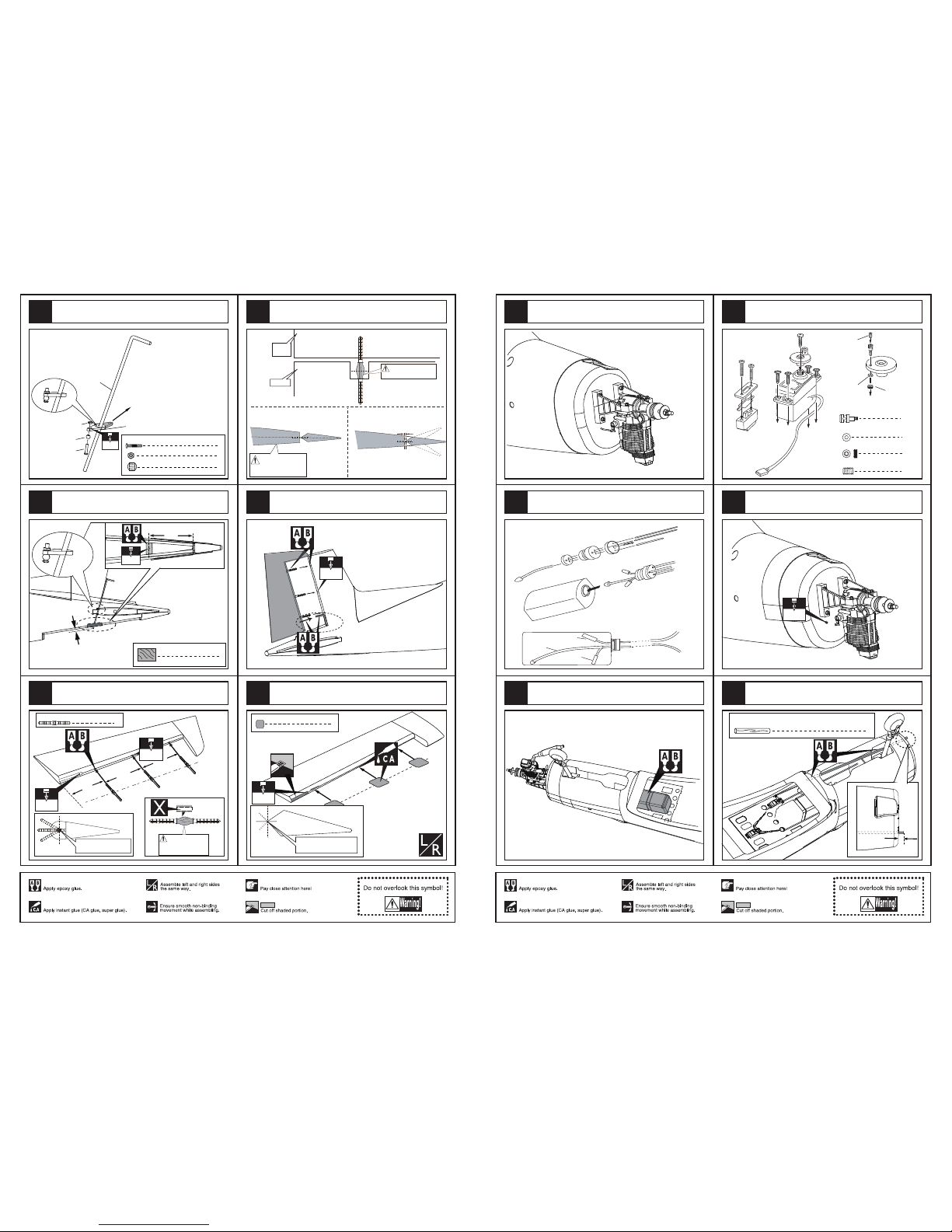
Install the rudder servo.
Install the elevator servo.
Assemble the rudder servo to appropriate position in
the fuselage.
CC’
DD’
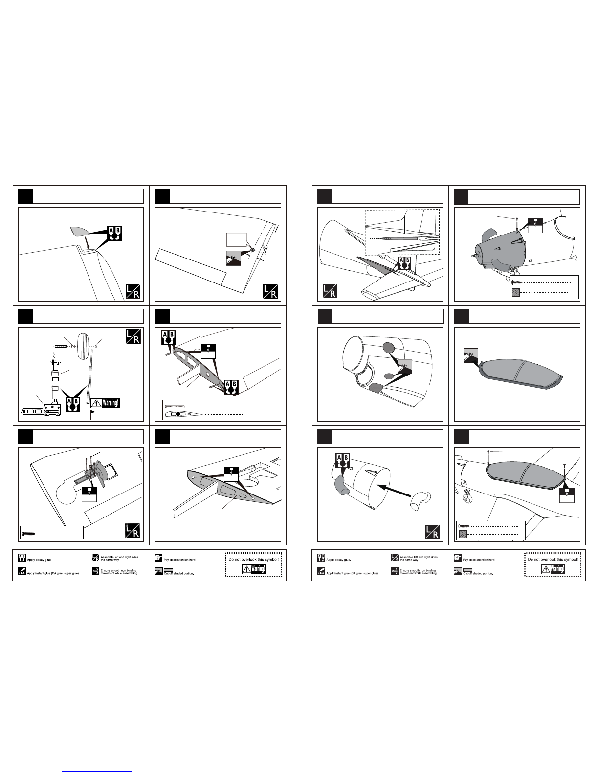
Make sure to glue securely.
If not properly glued, a failure in flight may occur.
Temporarily fasten down the main wing and
check its correct position.
Securely glue together.If coming off during flights,
you'll lose control of your airplane which leads
to accidents!
C=C'
D=D'
TP Screw (2.3x12mm)
open a hole on the covering for ensuring assemble and
demount the covering easily.
9
TP Screw (2.3x6mm)
Ply (15x15x3mm) 9
1.5mm
Assembly of the stabilizer.
Epoxy the plies to appropriate position under the tail landing
gear covering and assemble the tail landing gear covering
to the fuselage as below.
Assemble the elevator servo to appropriate position in
the fuselage.
8
43
42
39
41 44
40
2
Steel wire (0.5x1200mm)
1.5mm
4
TP Screw (3x20mm)
Collar (5mm) 2
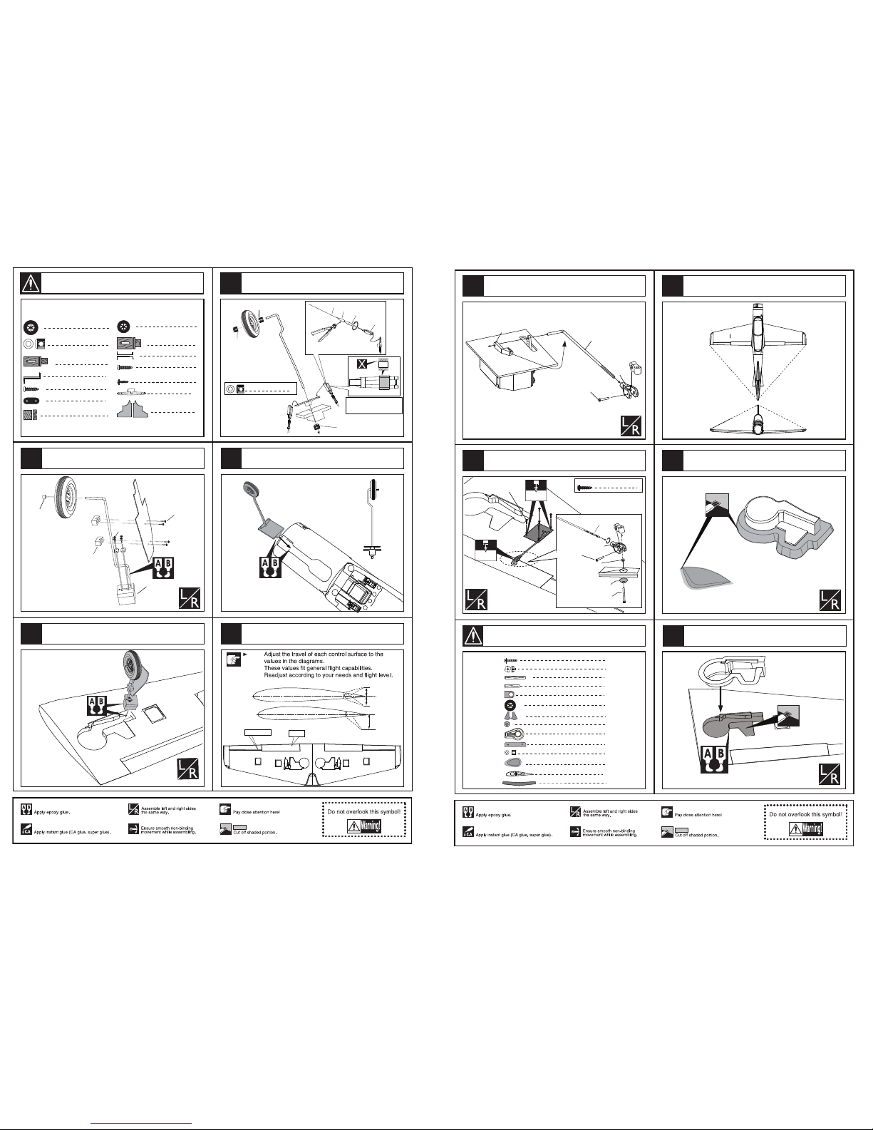
1
Wheel (75 mm)
1
TP Screw (3x20mm)
Steering fullarm (60x6mm)
2
Steel wire (0.5x1500mm)
TP Screw (3x20mm) 4
8
TP Screw (2.3x12mm)
1
Steering fullarm (60x6mm)
Collar (5mm) 2
1
Wheel (75 mm)
2
Washer(4x8mm)
2
Screw (4x25mm)
1
Aluminum shaft(5x50mm)
2
Washer(4x8mm) 2
Screw (4x25mm)
1
Aluminum shaft(5x50mm)
Brass collar (5mm)
Brass collar (5mm)
Wheel (75 mm)
Aluminum shaft
Screw (4x25mm)
Screw (4x25mm)
Washer(4x8mm)
Washer(4x8mm)
Steering fullarm (60x6mm) 2
2
2
Clevis
Copper joiner
Aluminum tube(3x6mm)
2
2
Screw (2x10mm)
Nut (2mm )
2
Washer(2x5mm)
Steel wire
Copper joiner
Aluminum tube Lock Nut (2mm )
Screw (2x10mm)
Ball joint
Washer(2x5mm)
2
2
2
Clevis
Copper joiner
Aluminum tube(3x6mm)
2
2
Screw (2x10mm)
Nut (2mm )
2
Washer(2x5mm)
Assemble the servo to the relevant position in the fuselage.
Assemble the nose wheel.
Install the nose landing gear to appropriate
position in the fuselage.
Assemble the steeling fullarm around the landing gear.
Install the servo.
9
49
48
47
45
46
Accessory list for the coming installation steps.