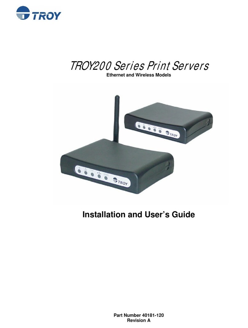
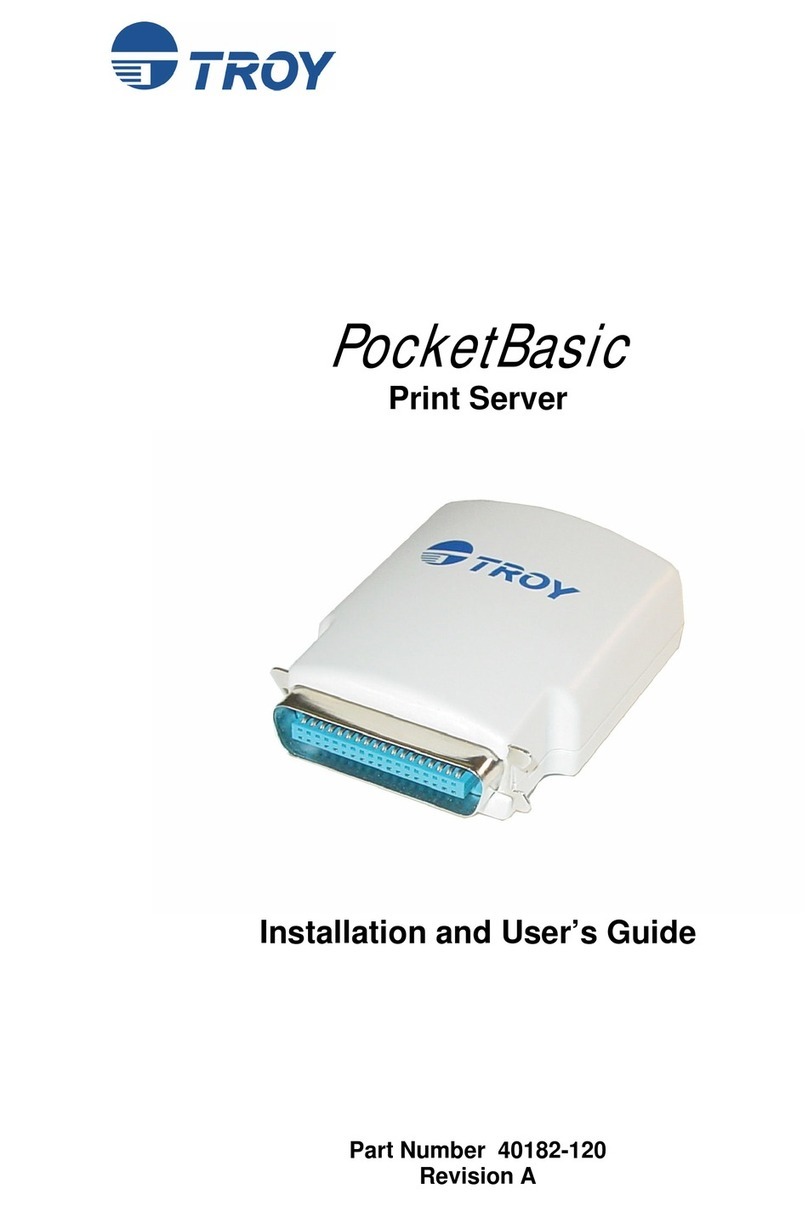
TROY Group Serial Servers Instructions for use

___________________________
TROY
Internet
Print Servers
Quick Install Manual
TROY Group, Inc.
2331 South Pullman St.
ISanta Ana, CA 92705-5571
TEL: (949) 250-3280
FAX: (949) 250-3283
http://www.troygroup.com

___________________________
Notice
TROY , INC. SPECIFICALLY DISCLAIMS THE IMPLIED WARRANTIES OF
MERCHANTABILITY AND FITNESS OF THIS PRODUCT FOR A
PARTICULAR PURPOSE. TROY shall not be liable for any errors contained in
this manual or for any damages resulting from loss of use, data profits, or any
incidental or consequential damages arising from the use of TROY products or
services.
Warning
This equipment has been tested and found to comply with the limits for a Class A
digital device pursuant to Part 15 of FCC Rules. These limits are designed to
provide reasonable protection against such interference when operating in a
commercial environment. This equipment generates, uses, and can radiate radio
frequency energy, and if not installed and used in accordance with this guide, may
cause harmful interference to radio communications.
Operation of this equipment in a residential area is likely to cause interference in
which case the user, at his or her own expense, will be required to take whatever
measures will be required to correct the interference.
Trademarks
HP, HP/UX, LaserJet, DesignJet, DeskJet, PaintJet, JetDirect, and JetAdmin are
trademarks of Hewlett-Packard Company. DEC, DECserver, VMS, LAT, and
ULTRIX are trademarks of Digital Equipment Corporation. UNIX is a trademark of
UNIX Systems Laboratories. Ethernet is a trademark of Xerox Corporation.
PostScript is a trademark of Adobe Systems Incorporated. NetWare is a trademark
of Novell, Inc. Apple, Macintosh, LaserWriter, and AppleTalk are trademarks of
Apple Computer, Inc. IBM, LAN Server, and AIX are trademarks of International
Business Machines Corporation. LAN Manager, Windows, and MS-DOS are
trademarks of Microsoft Corporation. VINES is a trademark of Banyan Systems
Inc. PrintKit is a trademark of Northlake Software. QADD is a trademark of
Network Compatibility Group. LAN Attached and UNIX Printing for VINES is a
trademark of Incognito Software Inc. XJet, XMark, XConnect, and XAdmin are
trademarks of TROY , Inc.
© Copyright 1992-2000 TROY , Inc. All rights reserved.

___________________________
Table of Contents
1. Introduction
External Print Server Models.............................................................1-1
Internal Print Server Models..............................................................1-3
2. Installing the Hardware
Unpacking and Handling...................................................................2-1
Setting the Switches (XJet IV-Plus and XConnect II).......................2-2
Pushbutton Switch.............................................................................2-3
XJet IV-2 Jumper Block....................................................................2-3
Connecting an Internal Print Server to the Printer ............................2-4
Connecting an External Print Server to a Parallel Printer..................2-5
Connecting a Print Server to a Serial Printer.....................................2-7
Ethernet Installation...........................................................................2-7
Verifying Successful Installation.......................................................2-9
3. Management Methods
TROY XAdmin32 ............................................................................3-1
TROY XAdmin ................................................................................3-1
TROY WebXAdmin.........................................................................3-1
TROY Print Server Console.............................................................3-1
HP JetAdmin......................................................................................3-2
HP WEb JetAdmin ............................................................................3-2
4. Setting the IP Address.....................................................................4-1
5. UNIX TCP/IP Host Configuration
Overview ...........................................................................................5-1
Berkeley UNIX Host Configuration..................................................5-4
Sun Solaris Configuration..................................................................5-4
HP/UX Configuration........................................................................5-5
IBM AIX Configuration ....................................................................5-6
Configuration on Other Systems........................................................5-7
Configuring Multiple Ports................................................................5-7
6. NetWare Network Configuration
Print Server Configuration Using XAdmin32 ...................................6-1
7. AppleTalk Network Configuration ...............................................7-1

8. Microsoft Network Configuration
Print Server Configuration................................................................. 8-1
Windows 95/98 and Windows NT Port Monitor Installation............8-1
Printer Setup for Windows 95/98......................................................8-2
Printer Setup for Windows NT 4.x....................................................8-3
Adding a Second NetBIOS Port........................................................8-3
Additional Configuration Methods....................................................8-4
9. DEC LAT Network Configuration ................................................ 9-1
10. Banyan VINES Network Configuration .....................................10-1
11. PrintraNet Internet Printing Configuration
Installing the Software on a Windows PC at the Local Site............11-1
Adding a Second PrintraNet Destination.........................................11-3
Configuring the Remote TROY Print Server .................................11-4
Printing to the Remote TROY Print Server....................................11-5
Troubleshooting...............................................................................11-6
12. JetSend Configuration .................................................................. 12-1
13. IPP Configuration ........................................................................13-1
14. Customer Support ........................................................................14-1

_____________________________________________________________
Introduction 1-1
1
Introduction
This manual is specifically for quick installation of your print server with
TROY recommended procedures. For more detailed configuration
instructions (including non-standard configurations), please refer to the
TROY Administrator’s guides located on the CD-ROM supplied with your
print server or on the TROY web site (http://www.troygroup.com).
External Print Server Models
The TROY Print Server family includes the following models:
• The Pony Print Server is the industry's smallest full-featured external
print server. It plugs directly into the parallel port of the printer, and
supports a 10baseT Ethernet interface. It is available in the following
models:
PPS-8S IPX/SPX, TCP/IP, AppleTalk, DLC/LLC,
NetBEUI/NetBIOS IP, Direct Mode IPX/IP,
http
PPS-8 IPX/SPX, TCP/IP, AppleTalk, DLC/LLC,
NetBEUI/NetBIOS IP, Direct Mode IPX/IP,
LAT, IP, http
PPS-8N IPX/SPX, TCP/IP, AppleTalk, DLC/LLC,
NetBEUI/NetBIOS IP, Direct Mode IPX/IP,
LAT, VINES IP, http
• The Pony 100 is a high-performance compact print server that plugs
directly into the parallel port of the printer. It supports both
100baseTX Fast Ethernet and 10baseT Ethernet, with the type of
network automatically sensed. A serial port is also included. It is
available in the following models:
PPS100-8S IPX/SPX, TCP/IP, AppleTalk, DLC/LLC,
NetBEUI/NetBIOS IP, Direct Mode IPX/IP,
http

_____________________________________________________________
1-2 Introduction
PPS100-8N IPX/SPX, TCP/IP, AppleTalk, DLC/LLC,
NetBEUI/NetBIOS IP, Direct Mode IPX/IP,
LAT, VINES IP, http
PPS100-8J (NetSend) JetSend, TCP/IP, NetBEUI/NetBIOS IP,
DLC/LLC, Direct Mode IP, http
• The XConnect II is an external print server. It features a high-speed
parallel port, a serial port, and both a thin Ethernet and UTP Ethernet
connector. It is available in the following models:
XConnect II-8S IPX/SPX, TCP/IP, AppleTalk, DLC/LLC,
NetBEUI/NetBIOS IP, Direct Mode IPX/IP,
http
XConnectII-8 IPX/SPX, TCP/IP, AppleTalk, DLC/LLC,
LAT, NetBEUI/NetBIOS IP, Direct Mode
IPX/IP, http
XConnect II-8N IPX/SPX, TCP/IP, AppleTalk, DLC/LLC,
NetBEUI/NetBIOS IP, Direct Mode IPX/IP,
LAT, VINES IP, http
XConnect II-8-LN03 XConnect II-8 with LN03 emulation option
•The XConnect 100 features 100baseTX capability for operation on
100 megabit/sec Fast Ethernet networks. It can also work on 10baseT
networks, so it is ideal for users who plan to upgrade to 100baseTX in
the future. The XConnect 100 has two high-speed parallel ports, and
two serial ports for networking up to four printers. It is available in four
models:
XConnect 100-8S IPX/SPX, TCP/IP, AppleTalk, DLC/LLC,
NetBEUI/NetBIOS IP, Direct Mode IPX/IP,
http
XConnect100-8 IPX/SPX, TCP/IP, AppleTalk, DLC/LLC,
LAT, NetBEUI/NetBIOS IP, Direct Mode
IPX/IP, http
XConnect 100-8N IPX/SPX, TCP/IP, AppleTalk, DLC/LLC,
NetBEUI/NetBIOS IP, Direct Mode IPX/IP,
LAT, VINES IP, http
XConnect 100-8-LN03 XConnect 100-8 with LN03 emulation
option

_____________________________________________________________
Introduction 1-3
Internal Print Server Models
The TROY Print Server family includes the following models:
• The XJet 3000 100baseTX/10baseT print server plugs into the
Enhanced I/O (EIO) slot on newer HP printers like the LaserJet 4000,
4050, 4500, 5000, 8000, 8100, Color LaserJet 4500/8500, and future
printers that use the EIO bus.
XJet 3000-8S IPX/SPX, TCP/IP, AppleTalk, DLC/LLC,
NetBEUI/NetBIOS IP, Direct Mode IPX/IP,
http
XJet 3000-8N IPX/SPX, TCP/IP, AppleTalk, DLC/LLC,
NetBEUI/NetBIOS IP, Direct Mode IPX/IP,
LAT, VINES IP, http
• The XJet 2000 10baseT pritn server plugs into the Enhanced I/O (EIO)
slot on newer HP printers like the LaserJet 4000, 4050, 4500, 5000,
8000, 8100, Color LaserJet 4500/8500, and future printers that use the
EIO bus.
XJet 2000-8S IPX/SPX, TCP/IP, AppleTalk, DLC/LLC,
NetBEUI/NetBIOS IP, Direct Mode IPX/IP,
http
XJet 2000-8N IPX/SPX, TCP/IP, AppleTalk, DLC/LLC,
NetBEUI/NetBIOS IP, Direct Mode IPX/IP,
LAT, VINES IP, http
• The XJet IV-Plus plugs into the Modular I/O (MIO) slot on HP
LaserJet IIISi, 4, 4M, 4 Plus, 4M Plus, 5, 5M, DeskJet
1200/1600/1600CM, DesignJet, DesignJet 600, DesignJet 750,
DesignJet 755CM, Color LaserJet, Color LaserJet 5/5M, and other
MIO-compatible printers. It includes both a 10baseT UTP and a
10base2 BNC Ethernet connector.
XJet IV-Plus-8S IPX/SPX, TCP/IP, AppleTalk, DLC/LLC,
NetBEUI/NetBIOS IP, Direct Mode IPX/IP,
http
XJet IV-Plus-8 IPX/SPX, TCP/IP, AppleTalk, DLC/LLC,
NetBEUI/NetBIOS IP, Direct Mode IPX/IP,
LAT, IP, http

_____________________________________________________________
1-4 Introduction
XJet IV-Plus-8N IPX/SPX, TCP/IP, AppleTalk, DLC/LLC,
NetBEUI/NetBIOS IP, Direct Mode IPX/IP,
LAT, VINES, http
XJet IV-Plus-8-LN03 XJet IV-Plus-8 with LN03 emulation option
• The XJet 100 provides both 100baseTX Fast Ethernet and 10baseT
Ethernet connectivity for HP MIO printers. The type of network is
automatically sensed.
XJet 100-8S IPX/SPX, TCP/IP, AppleTalk, DLC/LLC,
NetBEUI/NetBIOS IP, Direct Mode IPX/IP,
http
XJet100-8N IPX/SPX, TCP/IP, AppleTalk, DLC/LLC,
NetBEUI/NetBIOS IP, Direct Mode IPX/IP,
LAT, VINES, http
XJet 100-8J (NetSend) JetSend, TCP/IP, NetBEUI/NetBIOS IP,
Direct Mode IP, http
•The XJet IV-2 provides 10base2 BNC and 10base5 AUI Ethernet
connectivity for HP MIO printers. It is especially useful for connecting
to fiber optics transceivers.
XJet IV-2 IPX/SPX, TCP/IP, AppleTalk, DLC/LLC,
LAT, VINES, NetBEUI/NetBIOS IP, Direct
Mode IPX/IP, http
XJet IV-2-LN03 IPX/SPX, TCP/IP, AppleTalk, DLC/LLC,
NetBEUI/NetBIOS IP, Direct Mode IPX/IP,
LAT, VINES, http
These devices comply with Part 15 of the FCC Rules. Operation is subject to the
following two conditions: (1) These devices may not cause harmful interference
and (2) these device must accept any interference received, including interference
that may cause undesired operation.
The following information applies to the Pony Print Server Plus (PPS-8S,
PPS-8, and PPS-8N) only:
This equipment has been tested and found to comply with the limits for a Class B
digital device, pursuant to Part 15 of the FCC Rules. These limits are designed to
provide reasonable protection against harmful interference in a residential
installation. This equipment generates, uses and can radiate radio frequency energy
and, i
f
not installed and used in accordance to the instructions, ma
y
cause harm
f
ul

_____________________________________________________________
Introduction 1-5
interference to radio communications. However, there is no guarantee that
interference will not occur in a particular installation. If this equipment does cause
harmful interference to radio or television reception, which can be determined by
turning the equipment off and on, the user is encouraged to correct the interference by
one or more of the following measures:
1. Reorient or relocate the receiver.
2. Increase the separation between the equipment and the receiver.
3. Connect the equipment into an outlet on a circuit different from that to which the
receiver is connected.
4. Consult the dealer or an experienced radio/TV technician for help.


_____________________________________________________________
Hardware Installation 2-1
2
Installing the Hardware
Before You Start
TROY manufactures both internal and external print servers. Internal print
servers plug inside of the printer for maximum compactness and to
eliminate the need for an external power supply. Current TROY internal
print servers include the XJet IV-Plus, XJet IV-2, XJet 100, XJet 3000, and
XJet 2000 for Hewlett-Packard printers.
External print servers connect to the parallel port, or in some cases, to the
serial port of a printer. They have the advantage of working on virtually
any kind of printer. Current TROY external print servers include the
XConnect 100, Pony 100, XConnect II, and Pony Print Server Plus.
Before attempting to install a TROY print server, first make sure that you
have completed installing your printer or plotter as described in the
appropriate documentation for the device.
Unpacking and Handling
The TROY print server shipping box contains the following items:
1. TROY print server
2. TROY Print Server Software CD-ROM
3. TROY Quick Installation Manual
4. Power supply (external print servers only)
5. 1284C miniature Centronics to standard Centronics cable (XJet 2000
models only)
TROY print servers are designed to withstand normal handling procedures,
however reasonable precautions should be exercised during installation,
particularly with regard to static discharge.
• Make sure that you are adequately grounded by touching a bare metal
part of the printer while installing the print server.
• Avoid moving around the work area in order to eliminate static charge
buildup.
• If possible, do not work on a carpeted area.

_____________________________________________________________
2-2 Hardware Installation
Setting the Switches (XJet IV-Plus and XConnect II)
Note: Skip this section if you have an XJet IV-2, XJet 2000, XJet 3000,
XJet 100, XConnect 100, Pony Print Server Plus, or Pony 100.
The XJet IV-Plus and XConnect II print servers have 4 DIP switches (see
figure 2-1). These switches do not have to be changed for most printing
applications. The switch functions are as follows:
XJet IV-Plus switches:
Switch 1 Defines whether serial port will be used as a console
(OFF) or for a serial printer (ON).
Switches 2 & 3 ON for autosensing 10baseT and 10base 2 operation.
May be put in OFF position for 10baseT-only operation
(reduces power consumption)
Switch 4 Normally OFF. If put in the ON position, will restore the
print server to its factory default settings when the unit is
powered on again. If you use this switch, don’t forget to
return it to the OFF position after you restore the default
settings.
Figure 2-1
XJet IV-Plus and XConnect II switches
OFF
ON
OFF
ON
SW1 SW2 SW3 SW4
SW1
SW2
SW3
SW4
XConnect II
XJet IV-Plus

_____________________________________________________________
Hardware Installation 2-3
XConnect II switches:
Switch 1 Normally OFF. If put in the ON position, will restore the
print server to its factory default settings when the unit is
powered on again. If you use this switch, don’t forget to
return it to the OFF position after you restore the default
settings.
Switch 1 can also be used to print a self-test page. This is
done by moving the switch to the ON position and then
immediately returning it to the OFF position.
Switches 2 & 3 ON for autosensing 10baseT and 10base 2 operation.
May be put in OFF position for 10baseT-only operation
(reduces power consumption)
Switch 4 Defines whether serial port will be used as a console
(OFF) or for a serial printer (ON).
XJet 2000 XJet 100, Pony Print Server Plus, Pony 100, and XConnect 100
Pushbutton Switch
Note: Skip this section if you have an XJet IV-2, XJet IV-Plus, or XConnect II.
Newer TROY print servers have a single pushbutton test switch. It is used
as follows:
• To print a self-test page, press the switch in for at least one-eighth second but
less than five seconds.
• To reset the unit back to factory default settings, press the switch and
hold it in for at least 5 seconds
XJet IV-2 10base2/10base5 Jumper Block
Note: This section applies only to the XJet IV-2. Skip this section if you
have any other print server.
The XJet IV-2 uses a jumper block to set the Ethernet type as shown in
figure 2-2. If you are using thin Ethernet, make sure the block is set to the
position shown in figure 2-2A. If you are using the AUI (10base5) with the
HP LaserJet IIISi or 4Si (bottom slot only), with the DesignJet 600/650C,
or with a self-powered transceiver (for example, a DEC DELNI multiport

_____________________________________________________________
2-4 Hardware Installation
transceiver, which has its own power supply), move the jumper block to the
position shown in figure 2-2B.
If you are using AUI with any other printer besides the ones mentioned in
the previous paragraph, you must use the optional XJ12V voltage converter,
which provides the 12 volts necessary to power external transceivers. The
XJ12V replaces the jumper block and mounts on the XJet IV-2 as shown in
figure 2-2C.
Important Note: The XJ12V provides a maximum of 500mA of current, so
make sure that your transceiver does not exceed this limit.
Figure 2-2
Using the XJet IV-2 Jumper Block and XJ12V
Connecting an Internal Print Server to the Printer
XJet 3000 Installation
The XJet 3000 print server is compatible with EIO-based printers such as
the HP LaserJet 4000, 5000 and 8000.
The XJet 3000 plugs into the I/O slot located on the rear of your printer or
plotter The installation steps are as follows:
1. Turn off the printer or plotter and unplug the power cord.
B
(AUI)
A
(thin)
C
(XJ12V)
JP1 - JP10 JP1 - JP10 JP1 - JP10

_____________________________________________________________
Hardware Installation 2-5
2. If another I/O card is already installed in the I/O slot, loosen the two
thumbscrews and pull the card straight out. If no card is currently
installed, remove the faceplate by unscrewing the two retaining screws.
3. Insert the XJet 3000 into the I/O slot and tighten down the two
thumbscrews (see figure 2-3). Note: Some EIO printers have two slots.
The XJet 3000 may be installed in either slot.
Figure 2-3
Installing an XJet 3000 Print Server into the Printer
XJet 2000 Installation
The XJet2000 print server is compatible with EIO-based printers such as
the HP LaserJet 4000, 5000 and 8000.
The XJet 2000 plugs into the I/O slot located on the rear of your printer or
plotter The installation steps are as follows:
1. Turn off the printer or plotter and unplug the power cord.
2. If another I/O card is already installed in the I/O slot, loosen the two
thumbscrews and pull the card straight out. If no card is currently
installed, remove the faceplate by unscrewing the two retaining screws.

_____________________________________________________________
2-6 Hardware Installation
3. Insert the XJet 2000 into the I/O slot and tighten down the two
thumbscrews (see figure 2-4A). Note: Some EIO printers have two
slots. The XJet 2000 may be installed in either slot.
Figure 2-4
Installing an XJet Print Server into the Printer
4. Connect the cable from the XJet 2000 to the printer's parallel port (see
figure 2-4A).
Important Note: If you have a LaserJet 8000 or other printer that
uses the IEEE 1284C miniature Centronics connector instead of a
standard 36-pin Centronics connector, you must order the optional
CABLE-C/C 1284C-to-1284C cable.
This completes the hardware installation of the XJet 2000. Proceed to
Ethernet Installation section later in this manual.
XJet IV-Plus, XJet IV-2, and XJet 100 Installation
The XJet IV-Plus, XJet IV-2, and XJet 100 are print servers for MIO-based
printers such as the HP LaserJet IIISi, LaserJet 4, 4M, 4 Plus, 4M Plus, 4Si,
4Si MX, 4V, 4MV, 5, 5M, 5Si, 5Si MX, Color LaserJet, DesignJet, DeskJet
1200C/1600C, PaintJet XL300, and similar printers.
The XJet IV-Plus, XJet IV-2, and XJet 100 plug into the I/O slot located on
the rear of your printer or plotter. The installation steps are:
XJet IVl-Plus, XJet IV-2, XJet 100
Installation into Printer
XJet 2000
Installation into Printer
AB

_____________________________________________________________
Hardware Installation 2-7
1. Turn off the printer or plotter and unplug the power cord.
2. If another I/O card (such as the serial/parallel I/O interface card) is
already installed in the I/O slot, loosen the two thumbscrews and pull
the card straight out. If no card is currently installed, remove the
faceplate by unscrewing the two retaining screws.
3. Insert the XJet IV-Plus, XJet IV-2, or XJet 100 firmly into the slot, and
tighten the two screws (see figure 2-4B).
4. TROY recommends that AUTOCONTINUE be enabled on the LaserJet
so that minor errors do not interrupt the operation of the printer. Refer
to your printer manual for instructions on enabling this parameter.
Connecting an External Print Server to a Parallel Printer
XConnect II, Pony 100, and Pony Plus Print Server
• These print servers have a 36-pin male Centronics connector that is
compatible with the 36-pin female connectors found on most printers.
Therefore, the print server can be plugged directly into the printer with
no additional cable is required.
• In the event that the print server cannot be connected directly to the
printer's Centronics port, a 36-to-36 pin Centronics (male-to-female)
cable can be ordered from TROY (part Number: CABLE-CEN2).
• For printers like the LaserJet 8000 that use the miniature Centronics
IEEE 1284C, TROY offers the CABLE-C/B adapter cable.
XConnect 100:
• These print servers have two 25-pin female connectors that are
compatible with the IBM PC standard 25-to-36 pin Centronics cable.
This cable is available at any computer or office supply store, or it can
be ordered from TROY (part number CABLE-CEN).
• For printers like the LaserJet 8000 that use the miniature Centronics
IEEE 1284C, TROY offers the CABLE-C/A adapter cable.
Connecting a Print Server to a Serial Printer
XConnect II, Pony 100, XJet IV-Plus, XJet 100
The XConnect II has an RJ45 connector for connecting RS-232-compatible
serial printers. The XConnect II RJ45 connector is marked "Serial" and

_____________________________________________________________
2-8 Hardware Installation
should not be confused with the10baseT unshielded twisted pair connector,
which is also an RJ45. Note: The XJet 100 serial port can only be used to
connect a console terminal; it does not support a serial printer.
TROY offers the SCABLE-DB25M 25-pin male adapter cable kit for easy
connection to most printers. To assemble this kit, connect the wires to the
DB25 connector pins as follows:
Pin 2: Black Pin 3: Yellow Pin 4: Blue
Pin 5: White Pin 6: Brown Pin 7: Green
Pin 20: Orange (Red is not used)
Refer to the Administrator’s Manual or the TROY web site for more details
on serial port wiring.
The serial port is set by default to 9600bps, 8 bit characters, no parity, 1
stop bit. These settings can be changed using WebXAdmin or the print
server console as described in the Administrator’s Manual.
XConnect 100
The XConnect 100 has two standard PC-compatible 9-pin female D-
connectors. You can use the standard PC 9-pin to 25-pin adapter cable that
is available at any computer or office store. However, you will usually also
need a null modem (available at computer stores), because the XConnect
100 is a DTE device.
XJet 3000
The XJet 3000 uses a 9-pin female connector that is compatible with the
one used on many Hewlett-Packard printers, and is therefore compatible
with off-the-shelf cabling. It is different from other TROY products in that
this connector can be used for serial input applications. That is, the XJet
3000 basically adds a serial port to the printer, which allows the printer to
be connected serially instead of through the parallel port. This serial port is
set by default for serial input operation at 9600bps, 8 bits, no parity, 1 stop
bit, and XON/XOFF flow control. The default parameters can be modified
via the front panel on the printer, via WebXAdmin or the print server
console, or via the switch block on the printed circuit board. The port can
also be set to connect a console terminal by using the console command
SET PORT S1 CONSOLE ENABLED or by setting switches 1 through 4 to
the ON position (115.2Kbps is the default console speed). Operation of the
XJet 3000 serial port is described in greater detail in the Administrator's
Guide on the CD-ROM included with the print server.

_____________________________________________________________
Hardware Installation 2-9
Ethernet Installation
• The XJetIV-Plus and XConnect II can connect directly to either a
10baseT unshielded-twisted pair Ethernet or a 10base2 thin Ethernet
network (XConnect II Lite models have either a 10baseT or a 10base2
connector, but not both). The print server will automatically sense the
type of network.
• The XJet2000 and Pony Print Server Plus can connect to a 10baseT
Ethernet network.
• The XJet 3000, XJet100, XConnect 100, and Pony 100 can connect to
either a 100baseTX Fast Ethernet network or a 10baseT Ethernet
network. The print server will automatically sense the type of network.
• The XJet IV-2 connects to either a 10base2 or 10base5 network (make
sure that the jumper block is in the appropriate position as described
earlier in this chapter).
Connecting the print server to an Unshielded Twisted Pair Network
(100baseTX or 10baseT)
To connect an XJetIV-Plus, XJet 3000, XJet 100, XJet 2000, XConnect II,
XConnect 100, Pony Print Server Plus, or Pony 100 print server to an
unshielded twisted pair (UTP) Ethernet network, you will need an Ethernet
hub (with at least one unused port installed on your network) and an
appropriate length of RJ45 modular cable is needed. If you are connecting
an XJet 3000, XJet 100, XConnect 100, or Pony 100 to a 100baseT Fast
Ethernet network, you must use Category 5 RJ45 modular cable.

_____________________________________________________________
2-10 Hardware Installation
Figure 2-5
Connecting the Network
Connect one end of the RJ45 cable to the print server connector labeled
"10baseT" or "100baseTX/10baseT" and the other end to a port on the
twisted pair Ethernet hub
This completes the unshielded twisted pair Ethernet installation. Proceed to
the Verifying Successful Installation section.
Connecting the XJet IV-Plus, XJet IV-2, or XConnect II to a Thin
Ethernet Network
1. If you have an XJet IV-Plus or XConnect II, set switches 2 and 3
(10baseT/10base2) to the ON position if they are not already in the ON
position. If you have an XJet IV-2, make sure the jumper block is in
the correct position.
2. If you are installing the print server onto an existing network, connect
the print server’s BNC connector to the "T" connector (see figure 2-
5B).
3. If the "T" connector is not already installed then proceed as follows:
AB
H1000
1
2
Connecting to a UTP Ethernet Network Connecting to a Thin Ethernet Network
RJ45 unshielded
twisted pair cable
to hub
Other manuals for Serial Servers
1
This manual suits for next models
3
Table of contents
Other TROY Group Print Server manuals
