True Heading Vector Compact-S User manual

Vector Compact-S (NMEA 0183)
Vector Compact-N (NMEA 2000)
Quick Installation Guide
1
Ver. 3 2018

Vector Compact-S
2
Part Number Qty Part Name
0051-110-000
1
Vector
Compact-S GPS Compass
1
15m Power/Serial data cable
2
Screw hole caps
2
O
-Ring for screw hole cap
2
M6 x 14 mm SS hex mounting screws
1
Pole mounting base
1
Pole
lock nut; Hex 1”-14 UNF SS
NMEA 0183 (Serial) Kit
Screw Cap and
O-ring
M6x14 mm
Mounting
screws
Mounting Base
Locking Nut
15m power / serial
data cable
Front View Rear View

Vector Compact-N
3
Part Number Qty Part Name
0051-020-000
1
Vector
Compact-N GPS Compass
2
Screw hole caps
2
O
-Ring for screw hole cap
2
M6 x 14 mm SS hex mounting screws
1
Pole mounting base
1
Pole
lock nut; Hex 1”-14 UNF SS
NMEA 2000 Kit
Screw Cap and
O-ring
M6 x 14 mm
Mounting
screws
Mounting Base
Locking Nut
Front View Rear View

Vector Compact Dimensions
4
Dimension without base Dimension with base

Installation Considerations
5
Location
•Ensure that the Vector has a clear view of the sky
•Keep safe distances away from VHF antennas
•Route the cable the shortest way to a power
source or NMEA 2000 backbone (max 6 m)
•Mount the unit on a level plane
VHF antenna distance from the unit
Keep a minimum
radius of 1.0 m
(3.3’) from the
bottom
Keep a minimum
radius of 1.5 m
(4.9’) from the top

Mounting Options
Flush Mount
•The bottom of the vector compact has two holes for
flush mounting the unit to a flat surface .
6
Flush Mount Installation
•Create a drill template for the two mounting screws.
•Mark the hole centers onto the mounting surface using the drill template.
•Place the Vector Compact over the markings to ensure the planned hole
centers properly align.
•Use a nailset to mark the hole centers and drill the mounting holes to a
diameter of 6.5 mm (0.25”).
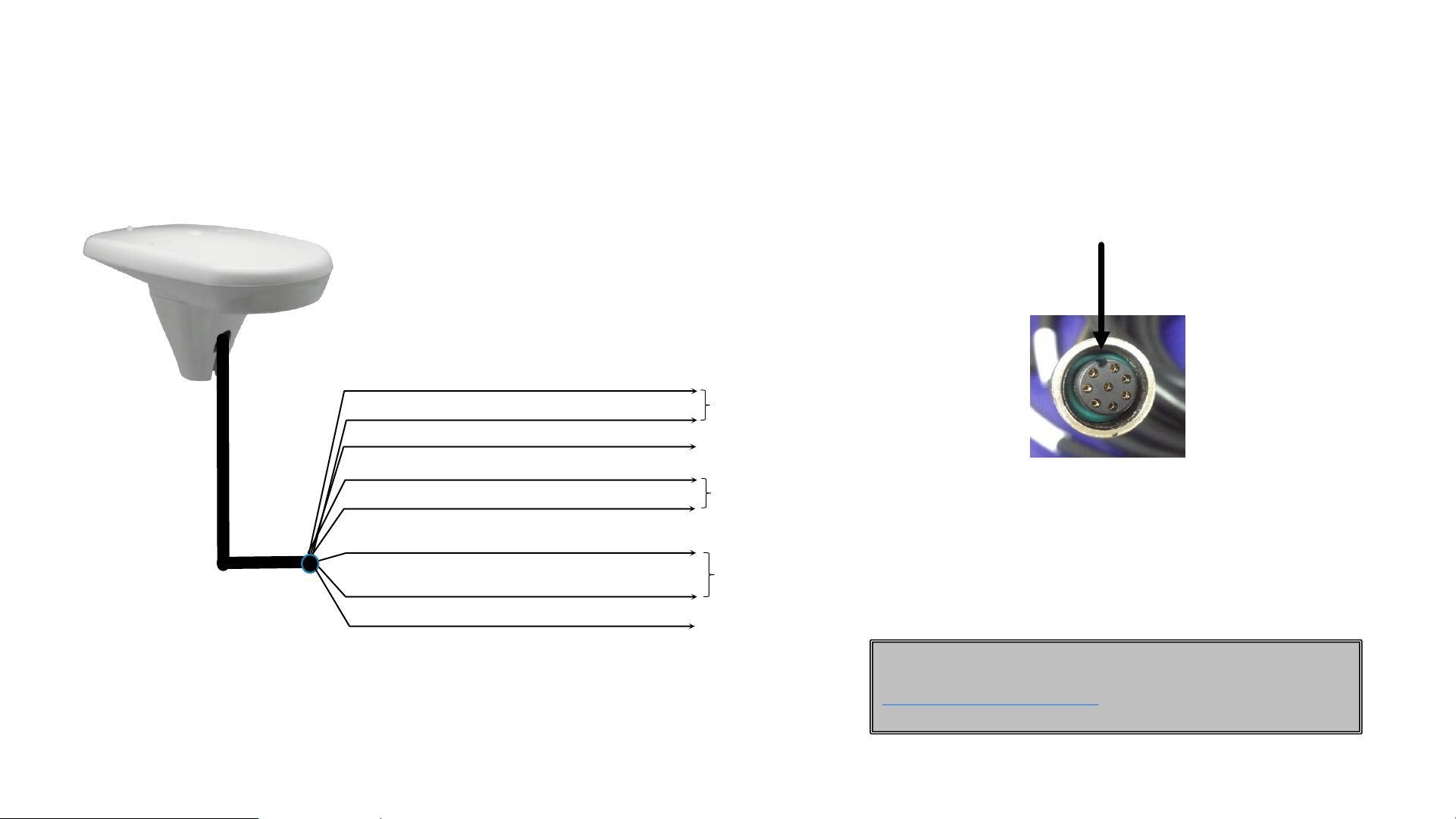
•Drill a 15 mm hole for the connector and pull the cable through the hole.
Connect to the Vector Compact and ensure that the connector locks with
a click.
•Place the Vector Compact over the mounting holes and insert the two M6
screws through the top. Secure the screws using washers and nuts,
preferably stainless steel (not supplied). Adjust the antenna using the
sight-line and tighten the screws.
Do not overtighten !
•Put the O-rings on each of the screw covers and place them over the
screw holes on the top of Vector Compact.
•
Warning: Overtightening the screws or connector may damage the unit!
Make sure that the vent hole is not covered !
Do not oversize the hole for
the connector to ensure
proper sealing
Drill the mounting holes to a
diameter of 6.5 mm (0.25”)
Recessed arrow located on the
bottom of the vector compact Vent hole

Mounting Options
Pole Mount
•Vector compact requires the mounting base,
mounting nut and M6 screws for pole mounting. The
mounting nut locks vector compact into the correct
orientation.
7
•Insert the NMEA2000 cable (not supplied) through the mounting pole,
nut and antenna mounting base.
•Mount the nut onto the pole followed by the mounting base. Adjust the
mounting base to the desired orientation.
•Tighten the nut to secure the orientation.
•Connect the NMEA2000 cable to the Vector Compact’s connector
located on the bottom of the unit.
•Place the Vector Compact on top of the mounting base and adjust the
antenna so that the base will fit the into the groove of the Vector
Compact. Press the antenna onto the base.
•Secure the Vector Compact onto mounting base using a 5 mm Allen
key to fasten the two M6 screws. Do not over-tighten the screws.
•Put the O-rings onto the screw caps and snap the caps over the
screw holes on top of the Vector Compact. Make sure that the
rectangular notch is facing towards the outside.
•Align the direction of Vector Compact and secure the unit using the
mounting nut (hand-tighten).
•
Warning: Overtightening of the screws and connectors may damage
the unit!
Pole Mount Installation
Screw Cap and
O-ring
M6x 14 mm
Mounting
screws
Mounting Base
Locking Nut
Screw
cap notch

Mounting Orientation
Perpendicular to the vessel center line (-S only)
•1. If the arrow on the antenna is pointing to the starboard side you
must set the heading bias value to +90°.
•2. If the arrow on the antenna is pointing to the port side of the
vessel the bias value must be set to -90°
•As the direction of the antenna is 90 degrees off the default
orientation the roll/pitch parameter must be set to ROLL to provide
correct calibration values if the antenna is not horizontal.
8
Parallel to the vessel center line
•The recommended installation is parallel to the vessels
center line. This is the default setting when the Vector
Compact is delivered.
•Mounting along the vessels centerline to the vessel the unit
should be set to PITCH mode (default) to provide correct
calibration values if the antenna is not horizontal.
The VectorPC software is required for programming the
Vector Compact -S parameters. VectorPC is available on
CD or download from http://www.trueheading.se

Alignment tools
Using the sight long side
•When the Vector Compact is mounted parallel to
the vessel center line the small post on the
opposite side of the unit from you, within the
channel made in the medallion located in the
center of the unit’s top as shown below. The
alignment accuracy is approximately (+ / -) 1°
Using the sight across short side
•When the Vector Compact is mounted
perpendicular to the vessel (only possible with
the –S version), use only the center sight located
in the center of the Vector Compact. The
alignment accuracy is approximately (+ / -) 2.5°
9

Pin 7, purple, port A, Transmit Data
Pin 6, orange, port A, Received Data
Pin 1, brown, Data GND
Port A
Pin 2, blue, port B, Received Data
Pin 5, green, port B, Transmit Data Port B
Pin 3, red, DC power input (+)
Pin 4, black, DC power ground (-)
Power
6 –36 VDC
Pin 8, yellow, 1PPS
How to connect the Vector Compact –S (serial)
Vector Compact-S
10
NMEA 0183
Use VectorPC for configuration of the “S” unit
. The
configuration software is available at
http://www.trueheading.se A serial to USB cable is
required for connecting the unit to the computer.
Key-way alignment
Rotate the cable ring clockwise until it locks.
The locking action is firm, but you will feel a
positive “click” when it has locked.

How to connect the Vector Compact –N (NMEA 2000)
11
Termination
Resistor
Power
Source
Mini Cable
(M to F)
Maximum
accepted
length 6 m
(19.7’)
Key-way alignment
Rotate the cable ring clockwise until it locks.
The locking action is firm, but you will feel a
positive “click” when it has locked.
Vector Compact-N NMEA 2000

Message Update Rate
Port A 4800
GPZDA 1
GPGLL 1
GPVTG 1
GPHDM 1
GPHDT 1
GPROT 1
Message Update Rate
Port B 4800
HEHDT 10
HEHDM 10
GPVTG 1
Vector Compact –S Configuration
NMEA 0183 (Serial)
12
Parameter Specification
Max DGPS Age
2700 second
Elevation Mask
5⁰
Differential Mode
SBAS (WAAS / EGNOS)
Feature
Normal Operation
Coasting
(no GPS)
Heading
GPS
Gyro
Heave
GPS
None
Pitch
GPS
Inertial
Roll
Inertial
Inertial
Vector Compact Defaults
Vector Compact –S Default Ports Configuration

Vector Compact –N NMEA 2000 Requested Messages
13
PG No.
Description (PGN)
Level
Update Rate
(msec)
Freq (Hz)
059392
ISO Acknowledgement
Used to acknowledge the status of
certain requests addressed to a specific
ECU.
B
On Request
On
Request
059904
ISO Request
Request the transmission of a specific
PGN, addressed or broadcast.
B
On Request
On
Request
060928
ISO Address Claim
Used to identify to other ECUs the
address claimed by an ECU
B
On Request
On
Request
126996
Production Information
NMEA 2000 database version
supported, manufacturer’s product
code, NMEA 2000 certification level,
Load Equivalency number, and other
product
-specific information.
B
On Request
On
Request
PG No.
Description (PGN)
Level
Update Rate
(msec)
Freq (Hz)
126464
Receive/Transmit PGNs group function
The Transmit / Receive PGN List Group
type of function is defined by first field.
The message will be a Transmit or
Receive PGN List group function.
B
On Request
On
Request
129538
GNSS Control Status
GNSS common satellite receiver
parameter status.
B
On Request
On
Request
129545
GNSS RAIM Output
Used to provide the output from a GNSS
receiver’s Receiver Autonomous
Integrity Monitoring (RAIM) process. The
Integrity field value is based on the
parameters set in PGN 129546 GNSS
RAIM Settings.
B
On Request
On
Request
129546
GNSS RAIM Settings
Used to report the control parameters
for a GNSS Receiver Autonomous
Integrity Monitoring (RAIM) process.
B
On Request
On
Request

Vector Compact –N NMEA 2000 Transmitted Messages
14
PG No.
Description (PGN)
Level
Update
Rate
(msec)
Freq (Hz)
126992
System Time
To provide a regular transmission
of UTC time and date. To provide
synchronism for measurement
data.
B
1000
1
127250
Vessel Heading
If the sensor value is Magnetic, the
deviation field can be used to
produce a Magnetic heading, and
the variation field can be used to
correct the Magnetic heading to
produce a True heading.
B
100
10
127251
Rate of Turn
Rate of change of the Heading.
B
100
10
127257
Attitude
Provides a single transmission that
describes the position of a vessel
relative to both horizontal and
vertical planes
B
1000
1
PG No.
Description (PGN)
Level
Update
Rate
(msec)
Freq (Hz)
127258
Magnetic Variation
Message for transmitting variation.
The message contains Heading or
Course over Ground. The quality of
service and age of service are
1000
1
128259
Speed
Provides a single transmission that
describes the motion of a vessel.
B
1000
1
129025
Position, Rapid Update
Provides latitude and longitude
referenced to WGS84.
B
100
10
129026
COG & SOG, Rapid Update
PGN that provides Course Over
Ground (COG) and Speed Over
Ground (SOG).
B
250
4

Vector Compact –N NMEA 2000 Transmitted Messages
15
PG No.
Description (PGN)
Level
Update
Rate
(msec)
Freq (Hz)
129027
Position Delta, High Precision
Rapid Update
The “Position Delta, High
Precision Rapid Update” This
PGN can provide delta position
changes down to 1 mm with a
delta time period accurate to 5
msec.
B
100
10
129028
Altitude Delta, High Precision
Rapid Update
The “Altitude Delta, High
Precision Rapid Update” This PGN
can provide delta altitude
changes down to 1 millimeter, a
change in direction as small as
0.0057
°, and with a delta time
period accurate to 5 msec.
B
100
10
129029
GNSS Position Data
Conveys a comprehensive set of
Global Navigation Satellite System
(GNSS) parameters, including
position information.
B
1000
1
PG No.
Description (PGN)
Level
Update
Rate
(msec)
Freq (Hz)
129033
Time & Date
Single transmission that provides
UTC time, UTC Date, and Local
Offset.
B
1000
1
129539
GNSS DOPs
GNSS status and dilution of
precision components (DOP) that
indicate satellite geometry to the
overall positioning error horizontal
(HDOP), Vertical (VDOP), and time
(TDOP).
B
1000
1
129540
GNSS SVs in View
GNSS information on current
satellites in view tagged by
sequence ID. Information includes
PRN, elevation, azimuth, SNR,
defines the number of satellites;
defines the satellite number and
the information.
B
1000
1
This manual suits for next models
3
Table of contents