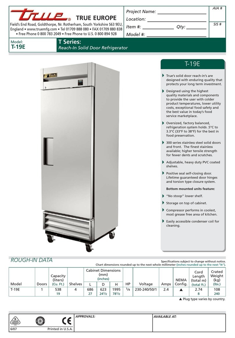
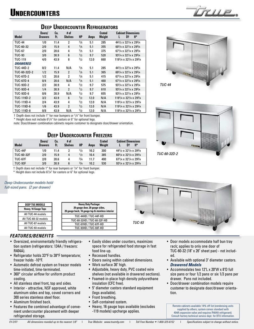
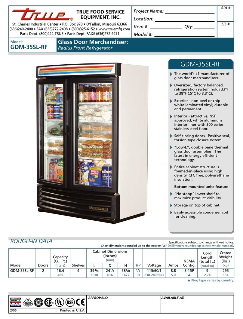
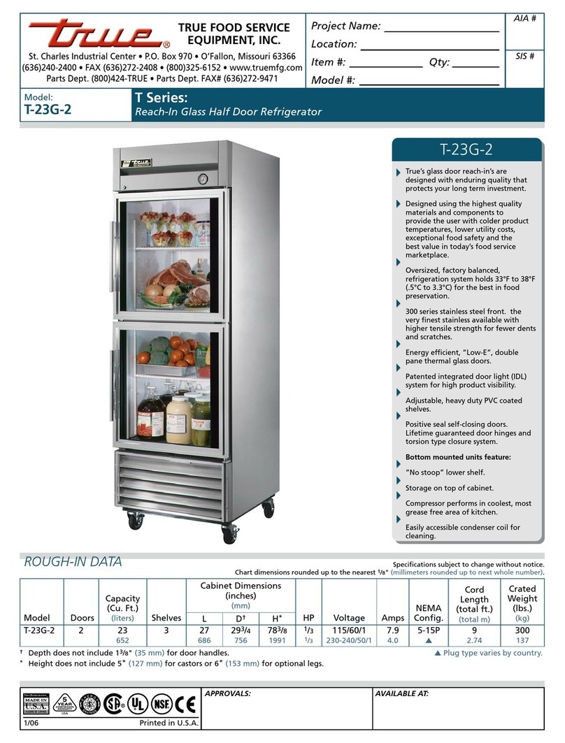
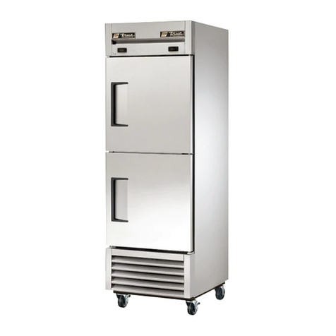
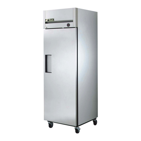
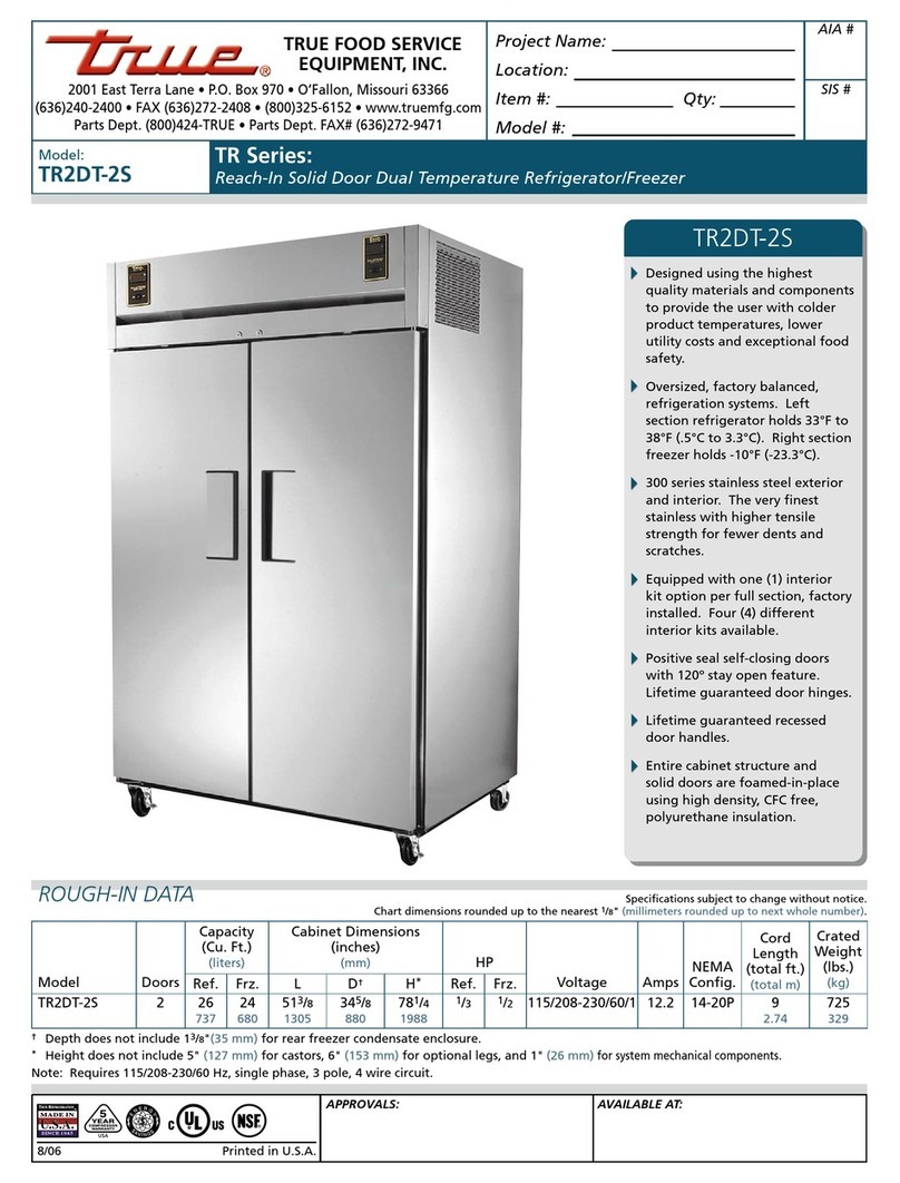
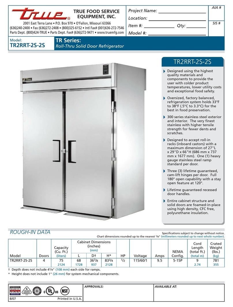
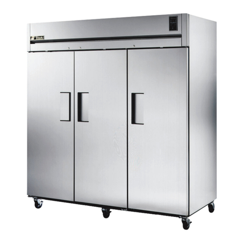
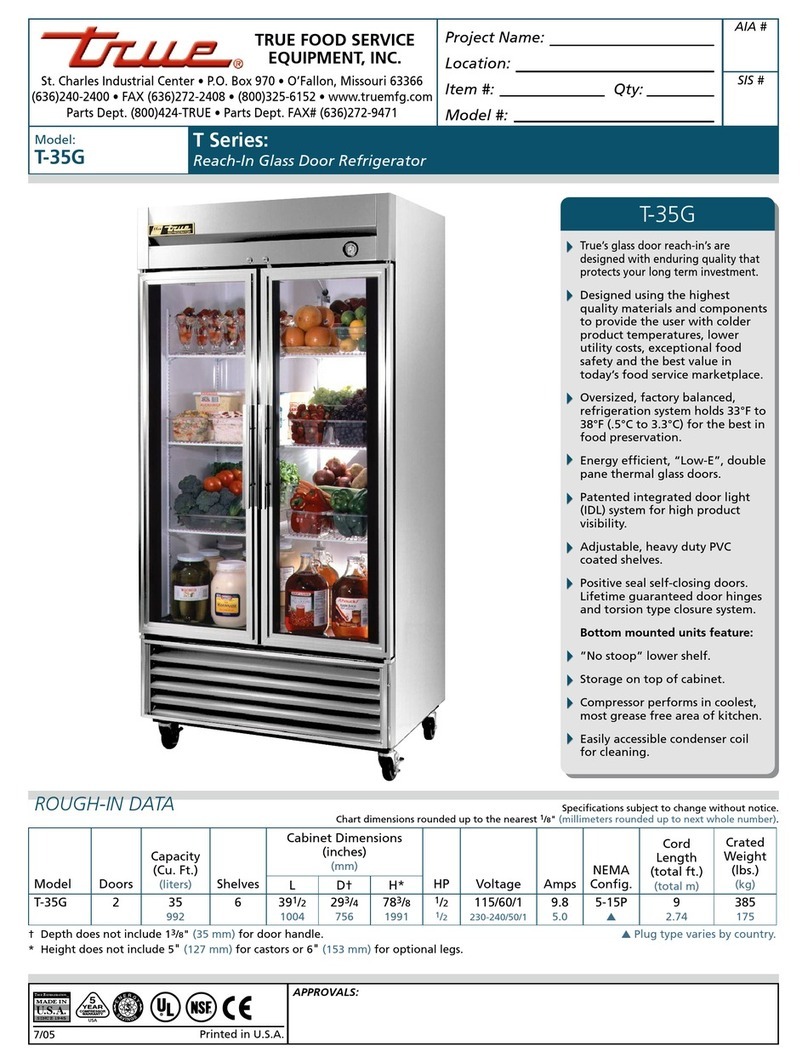
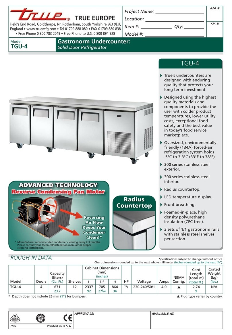
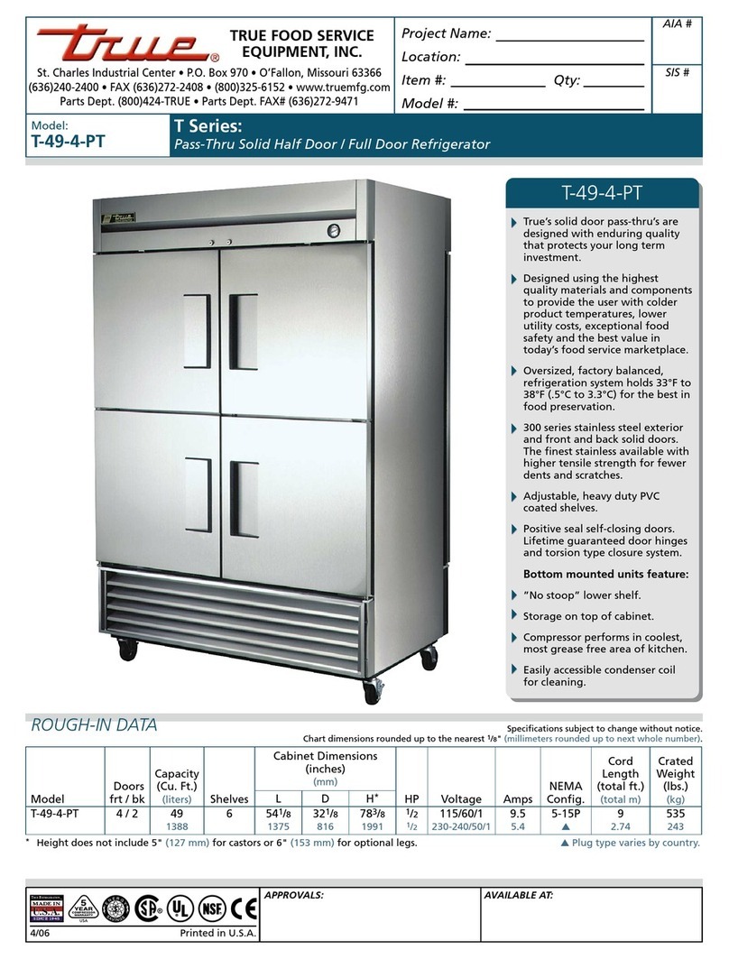
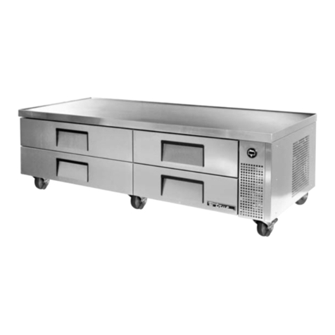
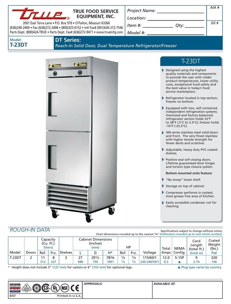
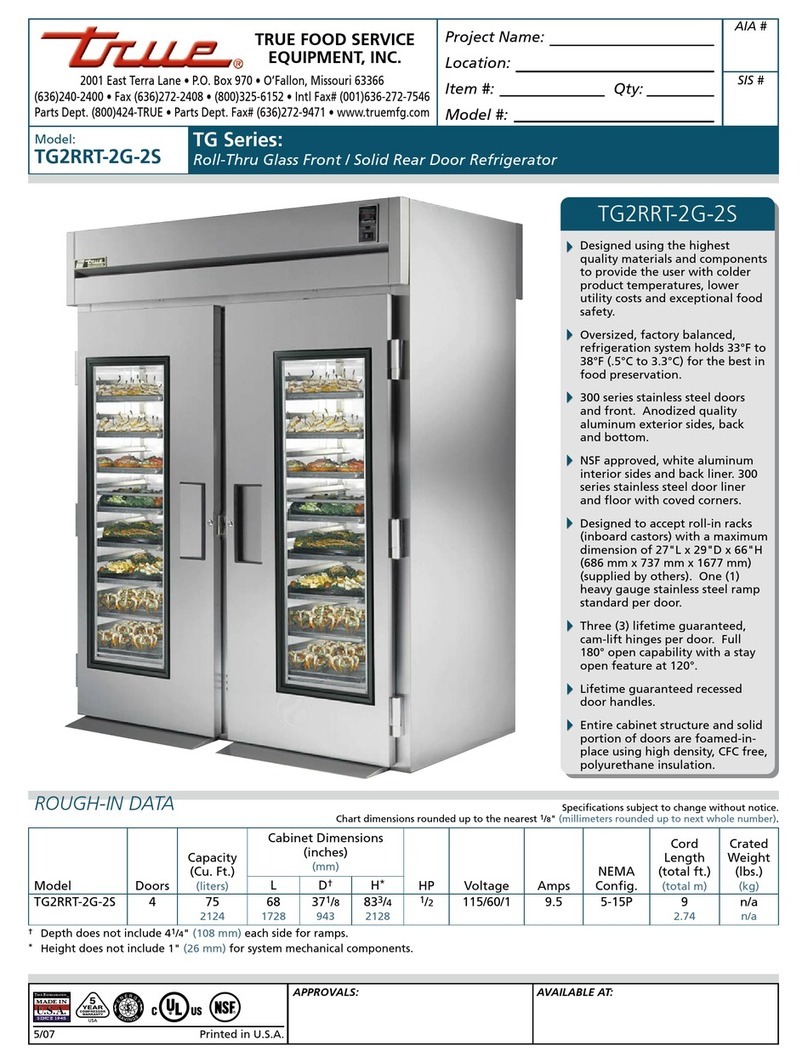
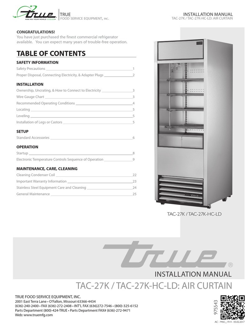
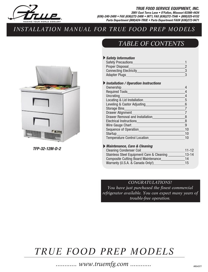
True TAC-30 User manual

............ www.truemfg.com ............
INSTALLATION MANUAL FOR AIR CURTAIN MODELS
TAC (TRUE AIR CURTAIN MODELS)
CONGRATULATIONS!
You have just purchased the finest commercial
refrigeration available. You can expect many years
of trouble-free operation.
TRUE FOOD SERVICE EQUIPMENT, INC.
2001 East Terra Lane • O’Fallon, Missouri 63366-4434
(636) 240-2400 • FAX (636) 272-2408 • INT’L FAX (636) 272-7546 • (800) 325-6152
Parts Department (800) 424-TRUE • Parts Department FAX# (636) 272-9471
TABLE OF CONTENTS
Safety Information
TAC-48 Installation Tips –––––––––––––––––––– 1
Safety Precautions –––––––––––––––––––––––– 2
Proper Disposal ––––––––––––––––––––––––––– 3
Connecting Electricity ––––––––––––––––––––– 4
Adapter Plugs –––––––––––––––––––––––––––– 4
Installation / Operation Instructions
Ownership ––––––––––––––––––––––––––––––– 5
Required Tools ––––––––––––––––––––––––––– 5
Uncrating –––––––––––––––––––––––––––––––– 5
Locating ––––––––––––––––––––––––––––––––– 6
Installation of Leg/Castors ––––––––––––––––––– 7
Electrical Instructions –––––––––––––––––––––– 7
Leveling Cabinet –––––––––––––––––––––––––– 7
Conductors and Circuits–––––––––––––––––––– 8
Start-up & Light Switch Location –––––––––––– 9
Mechanical Temperature Control
Adjustments ––––––––––––––––––––––––––– 10 -11
Defrost Timer Instructions ––––––––––––––––– 12
Digital Temperature Control Adjustments –– 13-14
LAE Temperature Control –––––––––––––– 15-23
Remote Unit Installation ––––––––––––––––––– 24
Shelving & Flavor Strip Installation ––––––– 25-26
Maintenance, Care & Cleaning
Cleaning Condenser Coil ––––––––––––––– 27-28
Stainless Steel Equipment Care & Cleaning 29-30
Light Bulb Replacement ––––––––––––––––––– 30
Warranty (U.S.A. & CANADA ONLY!) –––––––– 31
#897010
TAC-30
TAC-36
TAC-48
TAC-48GS
TAC-72RC

............ www.truemfg.com ............
True Food Service Equipment, Inc.

............ www.truemfg.com ............
True Food Service Equipment, Inc.
11

............ www.truemfg.com ............
True Food Service Equipment, Inc.
22
• Thisrefrigeratormustbeproperlyinstalled
andlocatedinaccordancewiththeInstallation
Instructionsbeforeitisused.
• Donotallowchildrentoclimb,standorhangonthe
shelvesintherefrigerator.Theycoulddamagethe
refrigeratorandseriouslyinjurethemselves.
• Donottouchthecoldsurfacesintherefrigerated
compartmentwhenhandsaredamporwet.Skin
maysticktotheseextremelycoldsurfaces.
• Donotstoreorusegasolineorotherflammable
vaporsandliquidsinthevicinityofthisoranyother
appliance.
• Keepfingersoutofthe“pinchpoint”areas;
clearancesbetweenthedoorsandcabinetare
necessarilysmall;becarefulclosingdoorswhen
childrenareinthearea.
NOTE
We strongly recommend that any servicing be performed
by a qualified individual.
• Unplugtherefrigeratorbeforecleaningand
makingrepairs.
• Settingtemperaturecontrolstothe0positiondoes
notremovepowertothelightcircuitorevaporator
fans.
WARNING!
Use this appliance for its intended purpose as described in this Owner Manual.
This cabinet contains fluorinated greenhouse gas covered by the Kyoto Protocol
(please refer to cabinet's inner label for type and volume,
GWP of 134a= 1,300. R404a= 3,800).
SAFETY PRECAUTIONS
When using electrical appliances, basic safety precautions should be followed, including the following:
How to Maintain Your Unit
to Receive the Most Efficient and
Successful Operation
You have selected one of the finest commercial refrigeration units made. It is manufactured
under strict quality controls with only the best quality materials available. Your TRUE cooler, when
properly maintained, will give you many years of trouble-free service.
SAFETY INFORMATION

............ www.truemfg.com ............
True Food Service Equipment, Inc.
33
SAFETY INFORMATION
PROPER DISPOSAL OF THE REFRIGERATOR
DANGER!
RISK OF CHILD ENTRAPMENT
USE OF EXTENSION CORDS
NEVER USE AN EXTENSION CORD! TRUE will not warranty any display case that has been connected to an extension cord.
Childentrapmentandsuffocationarenotproblemsof
thepast.Junkedorabandoneddisplaycasesarestill
dangerous…eveniftheywillsitfor“justafewdays.”If
youaregettingridofyourolddisplaycase,pleasefollow
theinstructionsbelowtohelppreventaccidents.
Before You Throw Away Your Old Refrigerator or Freezer:
• Takeoffthedoors.
• Leavetheshelvesinplacesothatchildrenmaynot
easilyclimbinside.
Refrigerant Disposal
Youroldrefrigeratormayhaveacoolingsystem
thatuses“OzoneDepleting”chemicals.Ifyouare
throwingawayyouroldrefrigerator,makesurethe
refrigerantisremovedforproperdisposalbya
qualifiedservicetechnician.Ifyouintentionally
releaseanyrefrigerantsyoucanbesubjectto
finesandimprisonmentunderprovisionsofthe
environmentalregulations.
REPLACEMENT PARTS
• Componentpartsshallbereplacedwithlikecomponents.
• Servicingshallbedonebyauthorizedservicepersonnel,tominimizetheriskofpossibleignitionduetoincorrect
partsorimproperservice.
• Lampsmustbereplacedbyindenticallampsonly.
• Ifthesupplycordisdamaged,itmustbereplacedbyaspecialcordorassemblyavailablefromthemanufactureror
itsserviceagent.

............ www.truemfg.com ............
True Food Service Equipment, Inc.
44
SAFETY INFORMATION
Thepowercordofthisapplianceisequippedwitha
groundingplugwhichmateswithastandardgrounding
walloutlettominimizethepossibilityofelectricshock
hazardfromthisappliance.
Havethewalloutletandcircuitcheckedbyaqualified
electriciantomakesuretheoutletisproperlygrounded.
Iftheoutletisastandard2-prongoutlet,itisyour
personalresponsibilityandobligationtohaveitreplacedwith
theproperlygroundedwalloutlet.
Theunitshouldalwaysbepluggedintoit’sown
individualelectricalcircuit,whichhasavoltagerating
thatmatchestheratingplate.
Thisprovidesthebestperformanceandalsoprevents
overloadingbuildingwiringcircuitswhichcouldcausea
firehazardfromoverheatedwires.
Neverunplugyourfreezerbypullingonthepowercord.
Alwaysgripplugfirmlyandpullstraightoutfromthe
outlet.
Repairorreplaceimmediatelyallpowercordsthathave
becomefrayedorotherwisedamaged.Donotuseacord
thatshowscracksorabrasiondamagealongitslengthor
ateitherend.
Whenremovingthefreezerawayfromthewall,be
carefulnottorolloverordamagethepowercord.
HOW TO CONNECT ELECTRICITY
Do not, under any circumstances, cut or remove the ground prong from the power cord.
For personal safety, this appliance must be properly grounded.
WARNING!
USE OF ADAPTER PLUGS
NEVER USE AN ADAPTER PLUG! Because of potential safety hazards under certain conditions, we strongly recommend against
the use of an adapter plug.
NEMAplugs
TRUEusesthesetypesofplugs.
Ifyoudonothavetherightoutlet
haveacertiedelectricianinstall
thecorrectpowersource.
115/60/1
NEMA-5-20R
115/208-230/1
NEMA-14-20R
115/60/1
NEMA-5-15R
208-230/60/1
NEMA-6-15R
NEMA plug configurations
T-Series and GDM Freezers
Spec Series same as T-Series
Back Bar
Milk Coolers
TSSU
TPP
TWT
TUC
TRCB
T-Series and GDM Refrigerators
Double Duty, Single Duty, Curved Glass
Horizontal Freezers
GDIM
TAC (Air Curtain)
115/60/1
NEMA-5-20R
115/208-230/1
NEMA-14-20R
115/60/1
NEMA-5-15R
208-230/60/1
NEMA-6-15R
NEMA plug configurations
T-Series and GDM Freezers
Spec Series same as T-Series
Back Bar
Milk Coolers
TSSU
TPP
TWT
TUC
TRCB
T-Series and GDM Refrigerators
Double Duty, Single Duty, Curved Glass
Horizontal Freezers
GDIM
TAC (Air Curtain)
208-230/60/1
NEMA-6-20R
Theincomingpowersourcetothecabinetincludingany
adaptersusedmusthavetheadequatepoweravailable
andmustbeproperlygrounded.Onlyadapterslisted
withULshouldbeused.

............ www.truemfg.com ............
True Food Service Equipment, Inc.
55
INSTALLATION / OPERATION INSTRUCTIONS
Toensurethatyourunitworksproperlyfromthefirst
day,itmustbeinstalledproperly.Wehighlyrecommend
atrainedmechanicandelectricianinstallyourTRUE
equipment.Thecostofaprofessionalinstallationis
moneywellspent.
BeforeyoustarttoinstallyourTRUEunit,carefully
inspectitforfreightdamage.Ifdamageisdiscovered,
immediatelyfileaclaimwiththedeliveryfreightcarrier.
TRUE is not responsible for damage incurred during shipment.
OWNERSHIP
• AdjustableWrench
• PhillipsHeadScrewdriver
• Level
REQUIRED TOOLS
Thefollowingprocedureisrecommendedforuncrating
theunit:
A. Removetheouterpackagingbypullingtri-wallnails
fromskid.Remove(4)cardboardcornerpadsand
dustcover.
B. Inspectforconcealeddamage.Again,immediatelyfilea
claimwiththefreightcarrierifthereisdamage.
C. Moveyourunitasclosetothefinallocationas
possiblebeforeremovingthewoodenskid.
UNCRATING
Installation Tips
• Placecabinetinanareathatwillnothaveanyairdrafts.
• Excessiveairflowaroundcabinetcaneffectinteriorcabinetairflow(air-curtain).
• NoHVACsupplyorreturnairventspushingairintoorpullingairoutofcabinet.
• Nodoorways.
• Noceilingfans.
• Donotplaceintodirectsunlight.
NOTE
Check for correct clearance space in back of cabinet and above. A 4” clearance requirement for the rear of cabinet and 12”
clearance above cabinet.
• Maximumambientcondition75degreesand55%RelativeHumidity.
INSTALLATION TIPS

............ www.truemfg.com ............
True Food Service Equipment, Inc.
66
INSTALLATION / OPERATION INSTRUCTIONS
A.Remove louver from the front of cabinet and backguard (if applicable) from rear of cabinet. Remove louver
grill by backing out Phillips screws located on either side of the louver grill. (See image 1). Pull the louver grill out from
the cabinet front. (See image 2). (To reinstall grill, place louver grill back into brackets located at the base of the unit. (See
image 3). Snap top of louver grill into place. Replace screws).
B. Skid bolts are located in each of 4 corners inside cabinet bottom (see image 4).
C. Remove skid bolts (see image 5).
D. Cut straps if applicable (see image 6).
E. Carefully lift cabinet off of skid.
LOCATING
WARNING: Be sure there is adequate ventilation in your room. Maximum ambient condition 75
degrees and 55% Relative Humidity. Warranty is void if ventilation is insufficient.
CLEARANCES (For proper cabinet operation, clearance guidelines should be followed).
Air Curtains – 4” at the rear and 12” at the top.
54 6
Removing skid from bottom of cabinet.
12
7 8
TAC-14GS Grill Removal:
Remove two screws from either side of the front grill (See image 7).
Lift grill away front cabinet (See image 8).
3

............ www.truemfg.com ............
True Food Service Equipment, Inc.
77
INSTALLATION / OPERATION INSTRUCTIONS
Leg levelers in the bottom of the cabinet
can be backed out for leveling.
Leg Levelers:
Ifthecabinetisnotleveluseanopen-endwrenchandturn
adjustabletipsonlegsuntilcoolerislevel.(Seeimage1).
Castor Installation:(KitContents)
2-Castormountingbracket
2-Castor,2-1/2”diameterwheelwith3/8”-16x1-
1/2”threadedstemwithoutbrake
2-Castor,2-1/2”diameterwheelwith3/8”-16x1-
1/2”threadedstemwithbrake
4-Washer,flat,3/8”I.D.x1”O.D.
4-Washer,splitlock,3/8”I.D.
4-Nut,hex,3/8”-16
(See image 2).
CAUTION
To avoid damage to lower rail assembly, slowly raise unit to
upright position after installing castors.
2
A. Beforeyournewunitisconnectedtoapowersupply,
checktheincomingvoltagewithavoltmeter.If
anythinglessthan100%oftheratedvoltagefor
operationisnoted,correctimmediately.
B. Allunitsareequippedwithaservicecord,andmust
bepoweredatproperoperatingvoltageatalltimes.
Refertocabinetdataplateforthisvoltage.
TRUErequiresthatasolecircuitbededicatedfortheunit.
Failuretodosovoidswarranty.
WARNING
Compressor warranties are void if compressor burns out due
to low voltage.
WARNING
Power supply cord ground should not be removed!
WARNING
Do not use electrical appliances inside the food storage
compartments of the appliances unless they are of the
type recommended by the manufacturer.
NOTE
To reference wiring diagram - Remove lower rear grill. Wiring
diagram is positioned on the inside cabinet wall.
ELECTRICAL INSTRUCTIONS
LEVELING
Securing Castors
A. Setunitinitsfinallocation.Besurethereisadequate
ventilationinyourroom.Underextremeheat
conditions,youmaywanttoinstallanexhaustfan.
WARNING
Warranty is void if ventilation is insufficient.
B. ProperlevelingofyourTRUEcooleriscriticalto
operatingsuccess(fornon-mobilemodels).Effective
condensateremovalanddooroperationwillbe
effectedbyleveling.
C. Thecoolershouldbeleveledinsidethecabinetfront
tobackandsidetosidewithalevel.
D. Ensurethatthedrainhoseorhosesarepositionedin
thepan.
E. Freeplugandcordfrominsidethelowerrear
ofthecooler(donotplugin).
F. Theunitshouldbeplacedcloseenoughtothe
electricalsupplysothatextensioncordsarenever
used.
WARNING
Cabinet warranties are void if OEM power cord is tampered
with. TRUE will not warranty any units that are connected to an
extension cord.
INSTALLATION OF LEGS AND CASTORS
1
............ www.truemfg.com ............
True Food Service Equipment, Inc.
88
INSTALLATION / OPERATION INSTRUCTIONS
CONDUCTORS AND CIRCUITS
Wire Gauge for 2% Voltage Drop in Supply Circuits.
115 Volt Distance In Feet To Center of Load
Amps 20 30 40 50 60 70 80 90 100 120 140 160
2 14 14 14 14 14 14 14 14 14 14 14 14
3 14 14 14 14 14 14 14 14 14 14 14 12
4 14 14 14 14 14 14 14 14 14 12 12 12
5 14 14 14 14 14 14 14 12 12 12 10 10
6 14 14 14 14 14 14 12 12 12 10 10 10
7 14 14 14 14 14 12 12 12 10 10 10 8
8 14 14 14 14 12 12 12 10 10 10 8 8
9 14 14 14 12 12 12 10 10 10 8 8 8
10 14 14 14 12 12 10 10 10 10 8 8 8
12 14 14 12 12 10 10 10 8 8 8 8 6
14 14 14 12 10 10 10 8 8 8 6 6 6
16 14 12 12 10 10 8 8 8 8 6 6 6
18 14 12 10 10 8 8 8 8 8 8 8 5
20 14 12 10 10 8 8 8 6 6 6 5 5
25 12 10 10 8 8 6 6 6 6 5 4 4
30 12 10 8 8 6 6 6 6 5 4 4 3
35 10 10 8 6 6 6 5 5 4 4 3 2
40 10 8 8 6 6 5 5 4 4 3 2 2
45 10 8 6 6 6 5 4 4 3 3 2 1
50 10 8 6 6 5 4 4 3 3 2 1 1
Wire Gauge for 2% Voltage Drop in Supply Circuits.
230 Volt Distance In Feet To Center of Load
Amps 20 30 40 50 60 70 80 90 100 120 140 160
5 14 14 14 14 14 14 14 14 14 14 14 14
6 14 14 14 14 14 14 14 14 14 14 14 12
7 14 14 14 14 14 14 14 14 14 14 12 12
8 14 14 14 14 14 14 14 14 14 12 12 12
9 14 14 14 14 14 14 14 14 12 12 12 10
10 14 14 14 14 14 14 14 12 12 12 10 10
12 14 14 14 14 14 14 12 12 12 10 10 10
14 14 14 14 14 14 12 12 12 10 10 10 8
16 14 14 14 14 12 12 12 10 10 10 8 8
18 14 14 14 12 12 12 10 10 10 8 8 8
20 14 14 14 12 10 10 10 10 10 8 8 8
25 14 14 12 12 10 10 10 10 8 8 6 6
30 14 12 12 10 10 10 8 8 8 6 6 6
35 14 12 10 10 10 8 8 8 8 6 6 5
40 14 12 10 10 8 8 8 6 6 6 5 5
50 12 10 10 8 6 6 6 6 6 5 4 4
60 12 10 8 6 6 6 6 6 5 4 4 3
70 10 10 8 6 6 6 5 5 4 4 2 2
80 10 8 8 6 6 5 5 4 4 3 2 2
90 10 8 6 6 5 5 4 4 3 3 1 1
100 10 8 6 6 5 4 4 3 3 2 1 1

............ www.truemfg.com ............
True Food Service Equipment, Inc.
99
INSTALLATION / OPERATION INSTRUCTIONS
A. Thecompressorisreadytooperate.Plugintheunit.
PLEASE REVIEW THE FOLLOWING CAUTIONS WHEN THE
OPTIONAL HEATED PAN IS USED.
CAUTION
This unit has two power supply cords. Unplug both
cords before moving or servicing this appliance.
CAUTION
This unit has two power supply cords. Connect
each plug to a receptacle that is connected to an
individual branch circuit.
CAUTION
This unit has more than one disconnect switch (plug).
B. TemperaturecontrolsetatNo.4positiongives
refrigeratorsanapproximatetemperatureof33°Fto38˚F
(.5˚Cto3.3˚C).Allowunittofunctionseveralhours,
completelycoolingcabinetbeforechangingthecontrol
setting.
C. Excessivetamperingwiththecontrolcouldleadtoservice
difficulties.Shoulditeverbecomenecessarytoreplace
temperaturecontrol,besureitisorderedfromyourTRUE
dealerorrecommendedserviceagent.
D. GoodairflowinyourTRUEunitiscritical.Becareful
toloadproductsothatitneitherpressesagainsttheback
wall,norcomeswithinfourinchesoftheevaporator
housing.Refrigeratedairoffthecoilmustcirculatedown
thefrontoftheshelves.
NOTE
If the unit is disconnected or shut off, wait five minutes before
starting again.
RECOMMENDATION
Before loading product we recommend you run your TRUE unit empty
for two to three days. This allows you to be sure electrical wiring
and installation are correct and no shipping damage has occurred.
Remember, our factory warranty does not cover product loss!
REPLACEMENT PARTS
TRUE maintains a record of the cabinet serial number for your unit.
If at any time during the life of your display case, a part is needed,
you may obtain this part by furnishing the model number and serial
number to the company from whom you purchased the cabinet. Call
Toll-Free: (800)-424-TRUE (Direct to Parts Department). (800)-325-
6152 (U.S.A. & Canada only) or call: (636)-240-2400.
LIGHT SWITCH LOCATION:
The light switch is located behind the interior light on the ceiling.
Depending on the model the switch will be either on the left or right
side of the ceiling.
STARTUP
Serial Number
•Remotecabinetsmustbeorderedasremote.
Wedonotrecommendconvertingastandard
selfcontainedtoremotesystem.
• Allremotecabinetsmustbehardwired.
• Remotecabinetsarenotavailablewithcastors.
• Allremotecabinetscomestandardusing404Arefrig-
erant.
• Allremoteunitscomestandardwithexpansionvalve,
liquidlinesolenoid,heatedcondensatepan,and
defrosttimerwhenapplicable.
• ContactTRUETechnicalServiceforBTUrequire-
ments.
• Nowiringnecessarybetweencabinetand
condensingunit.
• AllremotecondensingunitspurchasedfromTRUE
are208/230voltssinglephase.
If you have any questions regarding this section, please
call TRUE at 1 (800) 325-6152.
REMOTE UNITS
(This section applies to remotes only!)

............ www.truemfg.com ............
True Food Service Equipment, Inc.
10 10
TAC MECHANICAL TEMPERATURE CONTROL
ALTITUDE ADJUSTMENT
Required Tools:
• PhillipsHeadScrewdriver
• 1/4"NutDriverBit
• Slotted(Standard)ScrewDriver
• 5/32"AllenKey
Temperature Control Adjustments:
STEP 1
Unplugthecooler.
Note (Refrigerators):
Temperature Control Knob Location:
Insidethecabinetatthebottomonthe
left-handsiderecessedinthebackof
cabinet.
STEP 2
Backouttwoscrews,onefromeach
bottomcornerofthecabinet.Thenthe
flooroftheunitcanbepulledoutofthe
cabinetandsettotheside.Becarefulnot
toscratchtheinsideofthecabinetwhen
liftingtheflooroutoftheunit.(See
figure1).
STEP 3
Shelfsupportsoneithersideofcabinet
comeoutbybacking-outthreehexscrews
(1/4")oneachside.Largerunitswillhave
acentershelfsupportthatwillneedtobe
removed.
STEP 4
Onceshelfsupportsareremoved
theevaporatorcoilcoverneedstobe
removed.Back-outfour1/4"hexscrews
locatedinsidebottomofthecabinet
ontherearwall.Thenpulloffcoverby
liftingthebottomout.Thetopofthe
coverwillslipdownwhileyouliftthe
bottomout.(Seefigure2).
NOTE
Carefully not to disconnect any wires.
WARNING
Wear protective gloves when lifting out
evaporator coil cover.
STEP 5
A5/32"AllenKeywillbeneededto
adjustthetemperaturecut-out.One
clock-wiseturnofthecut-outscrew
meansachangeintemperatureof2-3˚
warmer.(Seeimage3).
WARNING
Do not turn the cut-out screw more than
one turn from the factory setting.
INSTALLATION / OPERATION INSTRUCTIONS
Figure 1
Figure 2 Figure 3

............ www.truemfg.com ............
True Food Service Equipment, Inc.
11 11
TAC MECHANICAL TEMPERATURE CONTROL
ALTITUDE ADJUSTMENT ... CONTINUED ...
Temperature Control Adjustments
Anaircurtaintypeofmerchandiserisaffectedbythe
temperatureandrelativehumidityofthesurrounding
ambient.
A.Theadjustmentknobandbodyofthetemperature
controlismountedtotheleftinteriorbackpanelof
thecabinet,aboutsixinchesoffofthe"floor"ofthe
cabinet,inarecessedarea,neartheevaporatorcoil.
- Toraisetheproducttemperature(warm upthe
cabinet),turnthecontrolknobcounterclockwise.
- Tolowertheproducttemperature(cool downthe
cabinet),turnthecontrolknobclockwise.
B.Iftheabovedoesnotgivedesirableresults,further
adjustmentispossibleinthefield.Disconnectpower
tothecabinet.Removethefulllengthbackpanel
thatthetemperaturecontrolismountedto:(See
figure1&2).
Thetemperatureprobeisinsertedintheleftend
oftheevaporatorcoil.
- Toraisetheproducttemperature(warmupthe
cabinet),relocatethetemp.controlprobeinthetop
tubewelllocationintheendofthecoil.
- Tolowertheproducttemperature(cooldownthe
cabinet),relocatethetemp.controlprobeinthe
bottomtubewelllocationintheendofthecoil.
NOTE
The sensor end of the temp. control should be inserted in
the tube well until it stops (bottom out). Reassemble the
lower back panel, restart the unit and set the control to
midpoint "5", for further temperature adjustment.
INSTALLATION / OPERATION INSTRUCTIONS
End view - left end of the evaporator coil
Figure 1
Figure 2

............ www.truemfg.com ............
True Food Service Equipment, Inc.
12 12
INSTALLATION / OPERATION INSTRUCTIONS
DEFROST TIME CLOCK OPERATION
Instructions for TAC-48, TAC-48GS, and TAC-72RC models.
RECOMMENDED DEFROST
SETTINGS:
TRUEManufacturinghasfactory
setyourdefrosttimeclocktoa
recommendedtimeanddurationdefrost
scenario.YourTRUEequipmenthas
beendesignedforthreedefrostperiods
(6:00a.m.,2:00p.m.and10:00p.m.).If
youdecidetodeviatefromthesedefrost
timesettingspleasefollowtheprocedures
foradjustmentbelow.
NOTE:
Defrost timer will need to be set at current
time of day before plugging unit into power
supply. The defrost times have been set
from the factory. If you want to change
defrost times please read through the
defrost timer instructions.
REQUIRED TOOLS:
•PhillipsScrewdriver
•1/4”NutDriverorSocket
TAC Defrost Timer Location:
Defrosttimerislocatedinaballastbox
behindthefrontlouveredgrillontheleft
sideoftheunit.Fourcornerscrewson
thefrontlouveredgrillwillneedtobe
removed.eballastboxhastwo1/4”
hexheadscrewsthatneedtoberemoved
togainaccesstothedefrostcontrol.
Setting the timer:
(UNPLUG UNIT FROM
POWER SUPPLY!)
DO NOT SET THE TIME BY
ROTATING THE “OUTER” DIAL.
Turntheminutehandclockwiseuntilthe
timeofdayontheouterdialisaligned
withthetrianglemarkerontheinnerdial
(twoo’clockposition).
Adjusting The Defrost Timer:
(timeinitiated,timeterminated)
YourTRUEequipmentcontainsadefrost
systemthatistimeinitiatedandtime
terminated.WhileTRUErequiresa
minimum3defrostperiodsnottoexceed
30minutestheprocedureonthispage
shouldbefollowedtocustomizeyour
specicneeds.
Notice
If timer is not set for a minimum of 3
defrost per day for 30 minutes each, the
coil may develop excessive frost. This may
lead to system failure and product loss,
which is not covered under warranty.
efollowingproceduremaybefollowed
tocustomizeyourneeds.
Highusage,hightemperature,andhigh
humiditymayrequire4defrostsettings
perday.
WARNING
Always follow the
manufacturer’s recommended settings
when programming the amount and
duration of the
defrost cycles.
Defrost Timer Image 2
STEP 1
ewhitetabslocatedontheoutmost
areaofthetimeclockhavebeenfactory
setfor(6:00a.m.,2:00p.m.,and10:00
p.m.).Eachtabrepresents15minutes
ofdefrosttime.Noticethatateach
defrosttimetwowhitetabsaresetfor15
minuteseachforatotalof30minutesof
defrost.
STEP 2
Inordertoprogramthetimetobeginthe
defrostcycle,ipthewhitetabsouttoset
thedefrosttime.Toeliminateadefrost
timeipthewhitetabsbacktowardthe
centeroftheDefrostTimer.
STEP 3
TRUErecommendsa30minutedefrost
cyclethreetimesperday.
Defrost Timer Box Image 1
Outer most dial. White tabs represent 15
minutes of defrost time.
Time of day.
Inner most dial.

............ www.truemfg.com ............
True Food Service Equipment, Inc.
13 13
TAC DIGITAL TEMPERATURE CONTROL
OPERATION
Digital Temperature Control Commands
Use of LED
Each LED function is described in the following table.
KEY COMBINATIONS
Tolock&unlockthekeyboard.
HOW TO SEE THE MINIMUM TEMPERATURE:
1.Pressandreleasethekey.
2.The"Lo"messagewillbedisplayed
followedbytheminimumtemperature
recorded.
3.Bypressingthekeyorwaitingfor5
secondsthenormaldisplaywillberestored.
HOW TO SEE THE MAXIMUM TEMPERATURE:
1.Pressandreleasethekey.
2.The"Hi"messagewillbedisplayed
followedbythemaximumtemperature
recorded.
3.Bypressingthekeyorwaitingfor
5sthenormaldisplaywillberestored.
HOW TO RESET THE MAXIMUM AND MINIMUM TEMPERATURE
RECORDED:
Toresetthestoredtemperature,whenmaximumorminimum
temperatureisdisplayed:
1.PressSETkeyuntil"rST"labelstartsblinking.
HOW TO SEE AND MODIFY THE SET POINT:
1.PushandimmediatelyreleasetheSET
key:thedisplaywillshowtheSetpoint
value;
2.TheSETLEDstartblinking;
3.TochangetheSetvaluepushtheor
arrowswithin10seconds.
TO START A MANUAL DEFROST:
1.PushtheDefrostkeyformorethan2
secondsandamanualdefrostwillstart.
HOW TO LOCK THE KEYBOARD:
1.Keeptheandkeyspressed
togetherformorethan3seconds.
2.The"POF"messagewillbedisplayed
andthekeyboardislocked.Atthis
pointitisonlypossibletoviewtheset
pointandtheMAXIMUMORMINIMUM
temperaturesstored.
TO UNLOCK THE KEYBOARD:
1. Keeptheandkeyspressedtogetherfor
morethan3seconds.
2. The"PON"messagewillbedisplayedandthe
keyboardisunlocked.
INSTALLATION / OPERATION INSTRUCTIONS

............ www.truemfg.com ............
True Food Service Equipment, Inc.
14 14
DIGITAL TEMPERATURE CONTROLLER
PROGRAMMING INSTRUCTIONS CONTINUED ....

............ www.truemfg.com ............
True Food Service Equipment, Inc.
15 15
This cabinet operation is being controlled by an electronic temperature control.
For operation explanation please see one of the following options:
1. Paperwork in sleeve on cabinet leg. (please put this back in place when nished)
2. Our website, www.truemfg.com U.S. Commercial homepage under Support tab.
3. Contact our service department at:
US: 1.800.325.6152
UK: +44(0)1709.888080
Mexico: (52)555.804.6343/44
email: service@truemfg.com,
We want to make it very clear that all parameter set points on the LAE controller have been set at the
factory to optimize performance and adjusting any of these parameters in the eld will affect the
cabinet’s performance and could void the Warranty.
IF YOUR CABINET IS BUILT WITH THIS
TEMPERATURE CONTROL, PLEASE SEE THE
FOLLOWING INSTRUCTIONS.

............ www.truemfg.com ............
True Food Service Equipment, Inc.
16 16
LAE CONTROL
SEQUENCE OF OPERATION
1. Cabinet is plugged in.
a. Display will illuminate.
b. Interior light will illuminate on glass door models only. (If lights do not come on please see
instructions on following page(s).) Solid door cabinet lights are controlled by door switch.
2. After the LAE control preprogrammed time delay of 3 minutes, the compressor and evaporator fan(s) will start if
the control is calling for cooling.
a. Control may be already pre-programmed from the factory so at the start of every compressor cycle or
during a defrost cycle, the condenser fan(s) will reverse for 30 seconds to blow dirt off the condensing
coil.
3. The LAE control will cycle the compressor but may also cycle evaporator fan(s) on and off determined by the
Set-Point and Differential temperatures. (If the Set-Point needs to be changed due to conditions please see
instructions on the following page(s).)
a. The Set-Point is the preprogrammed temperature which shuts off the compressor.
b. The Differential is the preprogrammed temperature that is added to the Set-Point temperature that will
start the compressor.
Example: If the Set-Point is -9°F/-23°C and the Differential is 10°F/5°C
(Set-Point) -9°F + 10 (Differential) = 1°F
Or
(Set-Point) -23°C + 5 (Differential) = -18°C
The compressor and evaporator fan(s) will cycle off -9°F/-23°C
and back on at 1°F/-18°C
4. The LAE control may be preprogrammed to initiate defrost by interval or at specic times of day. (If additional
Defrost Intervals or Cycles are needed or a Manual Defrost is required due to conditions please see instruc-
tions on the following page(s).)
a. At this time the “dEF” will appear on the display and compressor will turn off until a preprogrammed
temperature or duration is reached. During this time for freezers only, evaporator fan(s) will also
turn off and the coil heater and drain tube heaters will also be energized.
b. After the preprogrammed temperature or duration for defrost has been reached there may be a short
delay for both the compressor and evaporator fans to restart. At this time “dEF” may still appear
on the display for a short time.
True Manufacturing recommends that ONLY the Set-Point and/or
Defrost Interval may be adjusted due to certain conditions.
This sequence is NOT model specific.
If you have any questions, please contact the Technical Service Department.
Phone: 800-325-6152 • Email: service@truemfg.com

............ www.truemfg.com ............
True Food Service Equipment, Inc.
17 17
LOCKING & UNLOCKING LAE CONTROLLER
WHY:
LOCKING OF CONTROL IS NECESSARY TO PREVENT
CHANGES TO PROGRAM THAT MAY AFFECT CABINET
OPERATION
HOW:
A. Tochangelocksettingpressandreleasetheinfobutton
.“t1”willappear.Seeimage1.
Presstheupbuttonuntil“Loc”appears.
Seeimage2.
B. Whilepressingandholdingtheinfobuttonpress
theupordownbuttontochangethelock
settings.If“no”appears,thecontrollerisunlocked.If“yes”
appears,thecontrollerislocked.Seeimages3and4.
C. Oncethelocksettinghasbeensetcorrectlyreleasethe
infobutton.
Wait5secondsforthedisplaytoshowtemperature.
Seeimage5.
1
2
5
LAE Electronic Control
Info/Set Point
Button
Manual Defrost/
Down Button
Manual Activation/
Up Button
Stand-By
Button
3Image 3:
If “no” appears
on screen,
the controller
is unlocked.
4Image 4:
If “yes” appears
on screen,
the controller
is locked.
Compressor
Running
Activation of 2nd
Parameter Set - NA
Alarm - NA
Cabinet in Defrost
Evaporator Fan
Running
LAE Control Icons

............ www.truemfg.com ............
True Food Service Equipment, Inc.
18 18
HOW TO TURN LIGHTS ON/OFF
WHY:
LIGHT MAY BE CONTROLLED BY LAE CONTROLLER OR INTE-
RIOR LIGHT SWITCH.
HOW:
A. Tocontrolinterior/signlightsbytheLAEController,
pressandreleasethe“ManualActivation”button.
B. Tocontrolinterior/signlightsbytheinteriordoor
switch,depresstherockerswitchtothe“ON”position.
LightSwitchislocatedoninsidetoprightortopleftof
theceiling.
ON Position
May need to unlock control.
LAE Electronic Control
Info/Set Point
Button
Manual Defrost/
Down Button
Manual Activation/
Up Button
Stand-By
Button
Compressor
Running
Activation of 2nd
Parameter Set - NA
Alarm - NA
Cabinet in Defrost
Evaporator Fan
Running
LAE Control Icons
Other manuals for TAC-30
3
This manual suits for next models
8
Table of contents
Other True Refrigerator manuals

True
True TSD-69G User manual

True
True TR1RRI-1S User manual

True
True T Series User manual

True
True GDM-33SL-60 User manual

True
True TUC-24 User manual

True
True T-23DT User manual

True
True TRCB-82-86 User manual

True
True T-19E User manual

True
True RESIDENTIAL TR-42SBS-SS-B Assembly instructions

True
True TS-49G User manual
Popular Refrigerator manuals by other brands

GE
GE CustomStyle GCL22QGT Dimensions and installation information

U-Line
U-Line 3000 SERIES User guide & service manual

ETNA
ETNA KKD4088 Instructions for use

Frigidaire
Frigidaire FPE-21TK Use and care guide

Continental Refrigerator
Continental Refrigerator SW48-10-FB Specification sheet

Logik
Logik LUL55B13 Service manual