truflo DAP Series Instruction manual
Installation,
Operation, &
Maintenance
Manual
A New Vision For Quality Pumps
DAP/DSP Series

2
This manual provides instructions for the Installation, Operation, and Maintenance of the TRUFLO DAP ANSI
Centrifugal Process Pump. This manual covers the standard production and common options that are
available. For special options, supplemental instructions are supplied. This Manual must be read and fully
understood before installation and start-up.
The design, materials, and workmanship incorporated in the construction of TRUFLO pumps make them
capable of giving, trouble-free service. The life and satisfactory service of any mechanical unit, however,
are enhanced and extended by correct application, proper installation, periodic inspection, condition
monitoring, and careful maintenance.
This instruction manual was prepared to assist operators in understanding the correct methods of installing,
operating, and maintaining these pumps.
TRUFLO shall not be liable for physical injury, damage or delays caused by a failure to observe the
instructions for Installation, Operation, and Maintenance contained in this manual.
Warranty is valid only when genuine TRUFLO parts are used.
Use of the equipment on a service other than stated in the warranty card will nullify the warranty, unless
written approval is obtained in advance from TRUFLO.
Additional manuals can be obtained by contacting your local TRUFLO representative or by calling 1-800-
789-7864.

3
CONTENTS
1. SAFETY
1-1 Nomenclature .............................................................................................................................................................................. 5
1-2 General Precautions ................................................................................................................................................................... 5
2. GENERAL INFORMATION
2-1 Pump Description ...................................................................................................................................................................... 6
2-2 Attached Information ............................................................................................................................................................... 7
2-2.1 Pump Nameplate .................................................................................................................................................................. 7
2-2.2 Included Information ........................................................................................................................................................... 7
2-3 Transportation & Storage ........................................................................................................................................................ 7
2-3.1 Storage Requirements ......................................................................................................................................................... 7
2-3.2 Handling / Lifting .................................................................................................................................................................. 8
3. INSTALLATION
3-1 Site / Foundation ........................................................................................................................................................................ 9
3-2 Level Baseplate ........................................................................................................................................................................... 9
3-3 Grout Baseplate .......................................................................................................................................................................... 9
3-4 Alignment Procedures .............................................................................................................................................................. 9
3-4.1 Alignment Check ................................................................................................................................................................... 10
3-5 Piping ............................................................................................................................................................................................ 10
3-5.1 General Notes ........................................................................................................................................................................ 10
3-5.2 Suction Piping ........................................................................................................................................................................ 11
3-5.3 Discharge Piping ................................................................................................................................................................... 11
3-5.4 Final Piping Check ................................................................................................................................................................ 12
4. OPERATION
4-1 Preparation for Start-up ............................................................................................................................................................ 13
4-1.1 Motor Rotation Check ........................................................................................................................................................... 13
4-1.2 Impeller Clearance Check .................................................................................................................................................... 13
4-1.3 Couple Pump and Driver ..................................................................................................................................................... 14
4-1.4 Lubricating Bearings .............................................................................................................................................................. 14
4-1.5 Shaft Sealing ............................................................................................................................................................................. 14
4-2 Start-Up ......................................................................................................................................................................................... 15
4-2.1 Priming the Pump .................................................................................................................................................................. 15
4-2.2 Starting the Pump .................................................................................................................................................................. 15
4-3 Operation ...................................................................................................................................................................................... 16
4-3.1 General Considerations ......................................................................................................................................................... 16
4-3.2 Break-In Period ........................................................................................................................................................................ 16
4-3.3 Operating at Reduced Capacity ......................................................................................................................................... 16
4-3.4 Operating Under Freezing Conditions ............................................................................................................................. 17
4-4 Shut-Down .................................................................................................................................................................................... 17
4-5 Final Alignment .............................................................................................................................................................................. 17
5. PREVENTIVE MAINTENANCE
5-1 General Comments ...................................................................................................................................................................... 18
5-2 Maintenance Schedule ............................................................................................................................................................... 18
5-2.1 Break-In Period ......................................................................................................................................................................... 18
5-2.2 Routine Maintenance Summary ........................................................................................................................................ 18
5-2.3 Routine Inspection .................................................................................................................................................................. 18
5-2.4 Monthly Inspection ................................................................................................................................................................. 18
5-2.5 Annual Inspection ................................................................................................................................................................... 18
5-3 Maintenance of Bearings ........................................................................................................................................................... 19
5-3.1 Oil Lubricated Bearings ......................................................................................................................................................... 19
5-4 Maintenance of Shaft Seals ...................................................................................................................................................... 20
5-4.1 Mechanical Seals ..................................................................................................................................................................... 20
5-4.2 Packed Back Cover .................................................................................................................................................................. 20

4
6. BREAKDOWN
6-1 Disassembly ................................................................................................................................................................................... 21
6-1.1 Pump from Baseplate ............................................................................................................................................................ 21
6-1.2 Disassembly of Bearing Housing ....................................................................................................................................... 21
6-2 Reassembly ................................................................................................................................................................................... 21
6-2.1 Inspections ................................................................................................................................................................................. 21
6-2.2 Seal Assembly ........................................................................................................................................................................... 24
6-2.3 Seal Testing ............................................................................................................................................................................... 24
6-2.4 Pump Assembly ....................................................................................................................................................................... 24
6-2.5 Motor and Coupling Assembly ........................................................................................................................................... 25
7. TROUBLE SHOOTING
7-1 Pump Troubleshooting Guide ................................................................................................................................................... 26
7-2 Mechanical Seal Troubleshooting Guide ............................................................................................................................... 27
8. PARTS BREAKDOWN
Sectional View of a Group 1 Pump ................................................................................................................................................. 28
Sectional View of a Group 2 Pump ................................................................................................................................................ 29
Sectional View of a Group 3 Pump ................................................................................................................................................ 30
APPENDIX –GENERAL ALIGNMENT INFORMATION
Set-Up .................................................................................................................................................................................................... 31
Measurement ....................................................................................................................................................................................... 31
Angular Alignment ............................................................................................................................................................................. 31
Parallel Alignment .............................................................................................................................................................................. 32
Complete Alignment ......................................................................................................................................................................... 33
DSP Series ............................................................................................................................................................................................. 33
Common Conversions ........................................................................................................................................................................ 34
5
1. SAFETY
1-1 NOMENCLATURE
This pump has been designed for safe and reliable operation when properly used and maintained in accordance with
instructions contained in this manual.
A pump is a pressure-containing device with rotating parts that can be hazardous. Operators and maintenance personnel
must realize this and follow safety measures. TRUFLO shall not be liable for physical injury, damage or delays caused by a
failure to observe the instructions in this manual.
Throughout this manual the words Warning, Caution, and Note are used to indicate procedures or situations that require
special operator attention.
WARNING
Warning is used to indicate the presence of danger that can cause severe personal injury, death, or substantial property
damage if the warning is ignored.
CAUTION
Caution is used to indicate the presence of a danger, which will, or can cause minor personal injury or property damage if
the warning is ignored.
NOTE: Operating procedure, condition, etc. which is essential to observe.
EXAMPLES;
WARNING
Pump shall never be operated without coupling guard
installed correctly.
CAUTION
Throttling flow from the suction side may cause
cavitation and pump damage.
1-2 GENERAL PRECAUTIONS
WARNING
Personal injury will result if procedures outlined in this manual
are not followed.
.
Never use heat to disassemble pumps due to risk of explosion from trapped liquid.
Never operate pump without coupling guard correctly installed.
Never operate pump beyond the rated conditions to which the pump was sold.
Never start pump without proper prime (sufficient liquid in pump casing).
Never run pump below recommended minimum flow or when dry.
Always lock out and tag out power to the driver before performing pump maintenance.
Never operate pump with discharge valve closed.
Never operate pump with suction valve closed.
Do not change conditions of service without approval of authorized TRUFLO representative.

6
2. GENERAL INFORMATION
2-1 PUMP DESCRIPTION
The Model DAP is a horizontal overhung, open impeller centrifugal pump that meets requirement of ANSI B73.1. The
model is based on 6 power ends and 31 hydraulic pump sizes. Groupings are as followed.
Group 1 ------------ 7 Pump sizes
Group 2 ------------ 14 Pump sizes
Group 3 ------------ 10 Pump sizes
Casing:
The pump casing is an end-suction and top discharge ANSI B73.1 design with 150lb ANSI raised face flanges as standard
inlet and outlet connections. Inlet and outlet connections are available in 150lb or 300lb flanges with raised or flat face
configurations. The casing is configured with a back pull out design, which allows complete disassembly without
disturbing the piping or motor. A rigid foot mount for maximum resistance to unanticipated load supports the casing.
Confined gasket between casing and back cover plate insures positive seal. Unit is also supplied with 1/4" NPT tap on the
discharge flange.
Impeller:
The impeller is an open design for maximum efficiency, hydraulically balanced, with the best wear characteristics and no
axial adjustments. The impeller is attached to the shaft by means of a MNPT bore on reverse side. The impeller has rear
pump out vanes to minimize back cover plate pressure. The impeller clearances can be set externally via jack bolts on
outboard side of the pump. Standard material for the impeller is 316 stainless steel (CF8M) unless the pump material is of
higher grade alloy. All impellers are dynamically balanced.
Back Cover Plate:
Standard design is cylindrical bore and oversized for increased circulation. Back cover plate can accept a variety of
mechanical seals, such as single, double (inside and out) unbalanced or balanced in any materials available. Flush plans
are available.
Bearing Housing:
The bearing housing shall be sealed with labyrinth style bearing isolators to prevent contamination of the bearing
lubricant. A large and easy to read 1” NPT sight glass and a magnetic filter shall be used.
Shaft:
Shaft is a heavy duty, solid shaft design with maximum diameter in critical areas and with minimum shaft overhang.
Maximum shaft deflection is less then 0.002” at the face of the back cover plate. Shaft is also stepped to fit a variety of
seal types. Standard shaft material is 316 stainless steel (CF8M) unless the pump material is of higher grade alloy.
Bearings:
The inboard bearing carries only radial load, it is free to float axially in the frame. The outboard bearing is shouldered and
locked to the shaft and housing to enable it to carry radial and thrust loads. All fits are precision machined to industry
standards. The inboard bearing is a single row deep groove ball bearing. The outboard bearing is a double row angular
contact bearing.
Shaft Sealing:
The back cover plate is available to fit a component seal, cartridge seal or packing.
Direction of Rotation:
Counterclockwise as viewed from casing, looking at the driver shaft.
7
2-2 ATTACHED INFORMATION
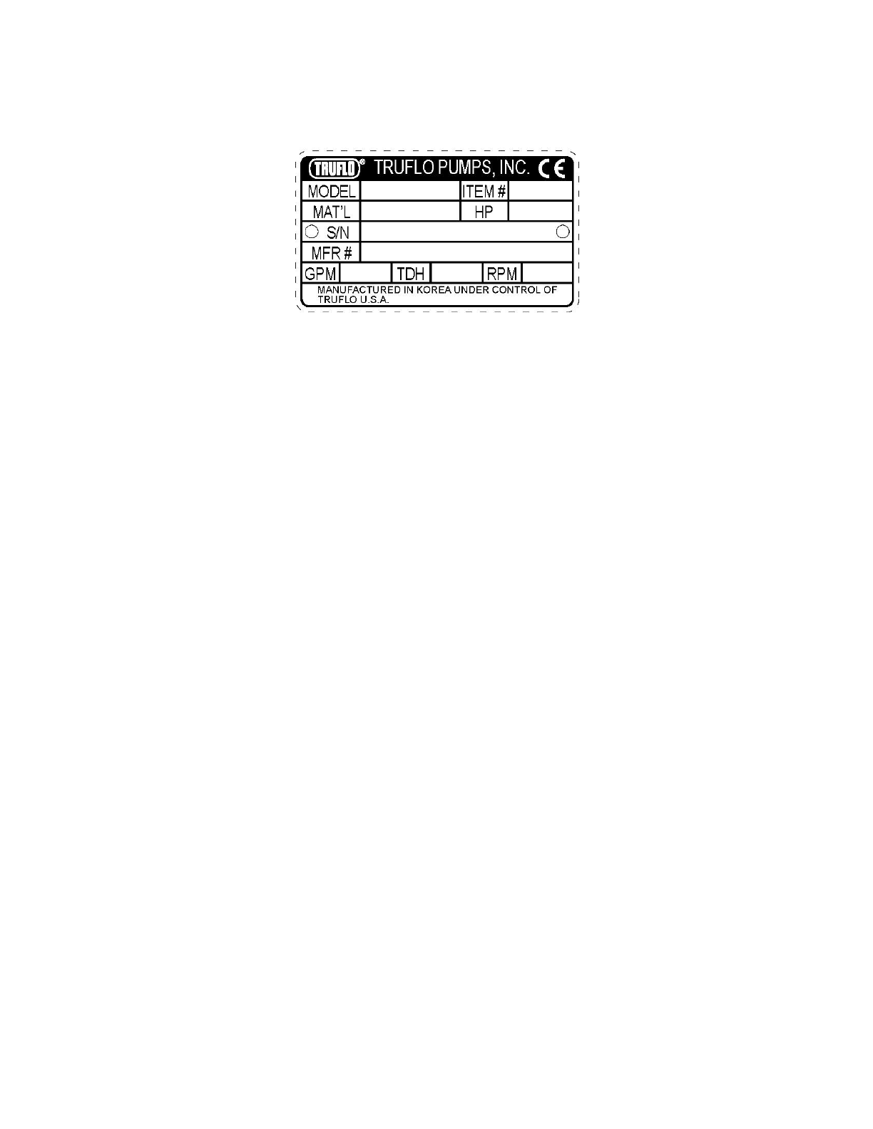
2-2.1 Pump Nameplate
Every pump has a TRUFLO nameplate that provides information about the pump. The nameplate is located on the bearing
adaptor.
The nameplate provides information about the pump’s characteristics. Note the format of the pump size: Suction Diameter
x Discharge Diameter - Impeller Diameter (inches). (Example: 3 x 1.5 - 6)
When ordering spare parts you will need to identify pump model, size, serial number, and the item number of required
parts. Information can be taken from the pump nameplate. Item numbers can be found in this manual.
2-2.2 Included Information
Each pump is sent with the following information in the form of attached tags, stickers and manuals:
1. Installation, Operation and Maintenance Manual
2. Stainless Steel Nameplate
3. Direction of Rotation Sticker
4. Label stating that the pump has been shipped without oil and requires oil before start up
5. Label stating that the pump needs to be realigned & rotation checked before start-up.
2-3 TRANSPORTATION & STORAGE
Inspect the pump as soon as it is received. Carefully check that everything is in good order. Make notes of damage or
missing items on the receipt and freight bill. File any claims with the transportation company as soon as possible.
2-3.1 Storage Requirements
Short Term: (less than 6 months) TRUFLO’s normal packing procedure is designed to protect pump during
shipping. Upon delivery of equipment, store in a covered and dry location.
Long Term: (more than 6 months) Preservative treatment of bearings and machined surfaces will be required.
Rotate shaft several times every 3 months. Refer to driver and coupling manufacturers for their long-term storage
procedures. Store in a covered dry location.

8
2-3.2 Handling / Lifting
WARNING
CAUTION
Pump and components are heavy. Failure to properly lift
and support equipment could result in serious physical
injury or damage to the equipment. Steel-toed shoes
must be worn at all times.
Use a forklift or an overhead crane with sufficient
capacity to move the equipment. Failure to do so
can result in physical injury or equipment damage.
WARNING:
All applicable regulations and standards must be followed when lifting equipment.
Assembled equipment and their components are very heavy. Failure to properly lift and support equipment can
result in serious physical harm and/or damage to the equipment.
Lift equipment only at the identified lifting points. Devices such as hoist rings, shackles, slings, straps, chains,
spreaders, etc. must be rated to support the entire weight of equipment.
Equipment and their components can be heavy. Use proper lifting methods and wear steel-toed shoes at all
times.
Do NOT lift equipment by shaft ends.
Do NOT combine or interchange different lifting methods.
Pump Type
Lifting Method
Bare Pump Only
Use a suitable sling attached properly to the casing, flanges, and/or frame.
Base Mounted Pump
Use suitable slings attached properly to the casing and the motor or baseplate. Use
lifting lugs or rings on the baseplate when available.
For concrete polymer baseplates, see the baseplate IOM manual for additional lifting
instructions.
Proper Lifting Method Examples
Figure 1:
Bare Pump Lifting Method
Figure 2:
Pump and baseplate lifting method.
Figure 3:
Pump, base and motor lifting method.
Figure 4:
Lifting method for baseplates
using lifting lugs or rings.

9
3. INSTALLATION
3-1 SITE / FOUNDATION
A pump should be located near the supply of liquid and have adequate space for operation, maintenance, and inspection.
1. Baseplate mounted pumps are normally grouted on a concrete foundation, which has been poured on a solid
footing. The foundation must be able to absorb any vibration and to form a permanent, rigid support for the
pumping unit.
2. The location and size of foundation bolts are shown on the outline assembly drawing provided with the pump
data package.
3. Foundation bolts most commonly used are sleeve type and J-type. Bolt designs permit movement for final bolt
adjustment.
3-2 LEVEL BASEPLATE
1. After mounting on the foundation examine the baseplate and make sure it is as level as possible.
2. Place 2 sets of wedges or shims on the foundation, one set on each side of every foundation bolt.
3. The wedges should extended 3/4 in (20mm) to 1.5 in (40mm) above foundation, to allow for adequate grouting.
This will provided even support for the baseplate once it is grouted.
4. Remove water and/or debris from anchor bolt holes/sleeves prior to grouting. If the sleeve type bolts are being
used, fill the sleeves with rags to prevent grout from entering.
5. Carefully lower baseplate onto foundation bolts.
6. Level baseplate to within 1/8 inch (3.2mm) over length of the baseplate and to within 0.088 inch (1.5mm) over the
width of the base by adjusting wedges.
7. Tighten bolts by hand.
3-3 GROUT BASEPLATE
1. Clean areas of baseplate that will contact grout. Do not use oil-based cleaners because grout will not bond to it.
(Refer to grout manufacturer’s instructions)
2. Build a dam around foundation. Thoroughly wet pump foundation.
3. Pour grout through grout hole in the baseplate, up to level of dam. Remove air bubbles from grout as it is poured
by patting, using a vibrator, or pumping the grout into place. Non-shrink grout is recommended.
4. Allow grout to set.
5. Fill remainder of baseplate with grout. Again remove air.
6. Allow grout to set at least 48 hours.
7. Tighten foundation bolts.
3-4 ALIGNMENT PROCEDURE
WARNING
Before beginning any alignment procedure make sure that
drive power is shut down. Failure to shut down driver power
will result in serious physical injury.
Alignment is achieved by adding or removing shims from under the feet of the driver/motor and adjusting equipment
horizontally as needed.
Note: Even though the pump was aligned after assembly prior to shipment, proper field alignment is the
responsibility of the installer and user of the unit.

10
Accurate alignment of the equipment must be attained. Trouble free operation can be accomplished by following these
procedures.
3-4.1 Alignment Check
Proper total alignment calls for alignment checks several times during the installation/start-up process. Below are
recommended points for which alignment is performed.
Before Grouting Baseplate –To ensure alignment can be obtained.
After Grouting Baseplate –To ensure no changes have occurred during grouting process.
After connecting pipe –To ensure pipe strains have not altered Alignment. If changes have occurred, alter piping to
remove pipe strains on pump flanges.
Final Alignment -Hot Alignment with pump heated to normal operating temperature.
Break In Period –Alignment check at this point will determine if pump system has moved out of alignment.
Obtain alignment when both pump and driver are at operating temperature. Thereafter, alignment should be
checked periodically according to plant operating procedures.
Note: Alignment check must be made after a process temperature change, piping changes and or pump
service is performed.
Note: Please refer to Appendix for Alignment Procedures and Guidelines
3-5 PIPING
3-5.1 General Notes
Guidelines for piping are given in the “Hydraulic Institute, Standards” available from: Hydraulic Institute, 30200 Detroit
Road, Cleveland, OH. 44145-1967 and must be reviewed prior to pump installation.
WARNING
Never draw piping into place by forcing at the flanged
connections of the pump. This may impose dangerous strains
on the unit and cause misalignment between pump and driver.
Pipe strain will adversely effect the operation of the pump
resulting in physical injury and damage to the equipment.
1. All piping must have an adequate number of pipe hangers and be aligned both axially and radially with the pump
flanges.
2. Piping runs should be as short as possible to minimize friction loss.
3. Do not connect piping to pump until grout has hardened and pump and driver hold-down bolts have been
tightened.
4. It is suggested that expansion loops or joints be properly installed in suction and/or discharge lines when handing
liquids at elevated temperatures, so linear expansion of piping will not draw pump out of alignment.
5. The piping should be arranged to allow pump flushing prior to removal of the unit on services handling corrosive
liquids.
6. Carefully clean all pipes, parts, valves and fittings, and pump branches prior to assembly.

11
3-5.2 Suction Piping
WARNING
NPSHA must always exceed NPSHRas shown on TRUFLO
performance curves received with order. (Reference Hydraulic
Institute for NPSH and pipe friction values needed to
evaluate suction piping.
Properly installed suction piping is a necessity for trouble-free pump operation.
Suction piping should be flushed before connection to the pump.
1. Use of elbows close to the pump suction flange should be avoided. There should be a minimum of 2 pipe
diameters of straight pipe between the elbow and suction inlet. Where used, elbow should be long radius.
2. Use suction pipe one or two sizes larger than the pump suction, with a reducer at the suction flange. Suction
piping should never be a smaller diameter than the pump suction.
3. Reducers, if used, should be eccentric, at the pump suction flange, with sloping side down.
4. Pump must never be throttled on suction side.
5. Suction strainers, when used, must have net “free area” of at least three times the suction pipe area.
6. Separate suction lines are recommended when more than one pump is operating from the same source of supply.
Suction lift conditions
1. Suction pipe must be free from air pockets.
2. Suction pipe must slope upwards to pump.
3. All joints must be airtight and tested
4. A means of priming the pump must be provided, such as a foot valve.
5. Piping allowances must be considered to allow air in case and suction piping to vent during priming.
Suction head/Flooded suction conditions
1. An isolation valve should be installed in the suction line at least two pipe diameters from the suction to permit
closing of the line for pump inspection and maintenance.
2. Keep suction pipe free from the air pockets.
3. Piping should be level or slope gradually downward from the source of supply.
4. No portion of the piping should extend below pump suction flange.
5. The size of entrance from supply should be one or two sizes larger than the suction pipe.
6. The suction pipe must be adequately submerged below the liquid surface to prevent vortices and air entrainment
at the supply.
3-5.3 Discharge Piping
Isolation and check valves should be installed in discharge line. Locate the check valve between isolation valve and pump;
this will permit inspection of the check valve. The isolation valve is required for priming, regulation of flow, inspection and
maintenance of pump. The check valve prevents pump from receiving damage due to reverse flow through the pump
when the driver is turned off.
Increasers if used, should be placed between pump and check valves.
Cushioning devices should be used to protect the pump from surge and water hammer if quick-closing valves
are installed in system.

12
3-5.4 Final Piping Check
After connecting the piping to the pump
1. Rotate shaft several times by hand to be sure that there is no binding and all parts are free.
2. Check alignment, per the alignment procedure outlined in section 3-5 to determine absence of pipe strain. If pipe
strain exists, correct piping.
Table 2
Alignment Troubleshooting
Problem
Probable Cause
Treatment
Unable to obtain horizontal
alignment, angular or parallel
Driver feet bolt bound
Loosen pump hold down bolts and slide
pump and driver until horizontal
alignment is achieved
Base plate not leveled properly,
Probably twisted.
Determine which corners of the
baseplate are high or low and remove
or add shims at the appropriate corners
and realign.
Unable to obtain vertical
alignment, angular or parallel
Base plate not leveled properly,
Probably tilted
Determine if center of baseplate should
be raised or lowered and correct by
evenly adding or removing shims at the
center of the baseplate.
13
4. OPERATION
4-1 PREPARATION FOR START-UP
4-1.1 Motor Rotation Check
CAUTION
Serious damage may result if pump is running in the wrong
rotation.
1. Lock out power to driver.
WARNING
Shut out driver power to prevent accidental start-up,
equipment damage and serious physical injury.
2. Make sure motor and pump are not coupled together before checking rotation of motor.
3. Make sure coupling hubs are securely fastened to shafts.
4. Unlock driver power.
5. Make sure everyone is clear. Jog driver just long enough to determine direction of rotation. Rotation must
correspond to arrow on bearing housing.
6. Shut out power to driver.
4-1.2 Impeller Clearance Check
Prior to starting the pump the impeller clearance must be checked. The pump efficiency is maintained when the proper
impeller clearance is set. The optimum hydraulic performance is attained by setting the impeller clearance at the factory to
predetermined limits that are consistent with service conditions.
The maximum impeller setting should not exceed more than 0.005 inch (0.13mm) above the values in table or significant
performance degradation will occur. TRUFLO pumps are designed such that, when new, the additional 0.005 inch
clearance maybe set between the pump casing and impeller.
For pumpage temperatures above 200F (93C) the cold (ambient) setting must be increased shown in Table 3. This is
necessary to prevent the impeller from contacting the casing due to expansion from the higher operating temperatures.
See Preventive Maintenance section for impeller adjustment procedure.
Table 3
Impeller Clearances
Cold temperature clearances for various service temperature
Service Temperature
Group 1
Group 2
Group 3
-20 to 200F (-29 to 93C)
0.005” (0.13mm)
0.008” (0.20mm)
0.015” (0.38mm)
200 to 250F (93 to 121C)
0.006” (0.15mm)
0.009” (0.22mm)
0.016” (0.41mm)
250 to 300F (121 to 149C)
0.007” (0.18mm)
0.010” (0.25mm)
0.017” (0.43mm)
300 to 350F (149 to 177C)
0.009” (0.22mm)
0.012” (0.30mm)
0.019” (0.48mm)
350 to 400F (177 to 204C)
0.010” (0.25mm)
0.013” (0.33mm)
0.020” (0.50mm)
400 to 450F (204 to 232C)
0.011” (0.28mm)
0.014” (0.35mm)
0.021” (0.53mm)
450 to 500F (232 to 260C)
0.012” (0.30mm)
0.015” (0.38mm)
0.022” (0.56mm)
500 to 550F (260 to 288C)
0.013” (0.33mm)
0.016” (0.41mm)
0.023” (0.58mm)
550 to 600F (288 to 316C)
0.014” (0.36mm)
0.017” (0.43mm)
0.024” (0.61mm)
600 to 650F (316 to 343C)
0.016” (0.40mm)
0.019” (0.48mm)
0.026” (0.66mm)
650 to 700F (343 to 371C)
0.017” (0.43mm)
0.020” (0.50mm)
0.027” (0.69mm)

14
4-1.3 Couple Pump and Driver
WARNING
Shut down driver power to prevent accidental rotation and
physical injury.
1. Install coupling per manufacturer’s instructions.
2. Install coupling guard. Refer to Coupling guard installation and Disassembly section
WARNING
Never operate a pump without coupling guard properly
installed. Refer to Appendix ll for coupling guard installation
instructions. Personal injury will occur if pump is run
without coupling guard.
4-1.4 Lubricating bearings
CAUTION
Pumps are shipped without oil in the bearing frame.
Oil Lubrication: Fill bearing frame with oil, through filler connection (located on top of bearing frame), until oil level
reaches the middle of the sight-glass. High quality turbine type oil, with rust and oxidation inhibitors should be used.
If pump is put into operation after prolonged shutdown. Flush out bearings and bearing frame with a light oil to remove
contaminants. During flushing, rotate shaft slowly by hand. Finally, flush bearing housing with proper lubricating oil to
ensure oil quality after cleaning.
See Preventive Maintenance section for lubrication recommendations.
WARNING
Operation of the unit without proper lubrication will cause
bearing failure, and pump seizure.
4-1.5 Shaft Sealing
TRUFLO ANSI Pumps may be supplied with either packing or Mechanical seals.
Packing Option: TRUFLO pumps may be sent with or without packing. Please examine the back cover plate upon arrival
to determine the status of packing material.
Mechanical Seal Option: Pumps may be shipped with or without mechanical seals installed. A common seal with this
model is the cartridge type. Cartridge seals are preset at the seal manufacturer’s facility and require no field settings.
Cartridge seals installed by the user require removal of handling clips prior to operation, allowing the seal to slide into
place. If the seal has been installed in the pump at the TRUFLO factory, these clips may have already been removed. For
other types of mechanical seals, refer to seal manufacturer’s instructions for installation and setting.

15
Connection of Sealing liquid
For satisfactory operation, there must be a liquid film seal between the faces to lubricate them. Refer to seal
manufacturer’s drawing for location of taps. Some methods that may be used to flush/cool the seal are:
1. Product Flushing –In this arrangement, the pumpage is piped from the casing (and cooled in an external heat
exchanger when required) then injected in seal gland.
2. External Flushing –A clean, cool compatible liquid is injected from an outside source directly into seal gland.
Flushing liquid must be a pressure 5-15 PSI (0.35-1.01 kg/cm2) greater than the back cover plate pressure.
Injection rate should be 0.5-2 GPM (2-8LPM).
3. Other methods may be used which make use of multiple gland connections and/or back cover plate connections.
Refer to documentation supplied with the pump, mechanical seal reference drawing, and standard ANSI sealing
piping diagrams.
Note: For further reference to sealing options please refer to section 6-2.3 seal testing, section 5-4.1 mechanical
seals and section 6-2.2 seal assembly.
4-2 START-UP
4-2.1 Priming the Pump
Never start the pump until it is properly primed. Several different methods of priming are used each depending upon type
of installation and service involved.
Suction Supply above Pump
1. Slowly open the suction valve.
2. Open air vents on the suction and discharge piping until liquid flows out.
3. Close the vent valves
4. Pump case is now full of liquid.
Suction Supply below pump
1. Close discharge valve and open-air vents in casing.
2. Open valve in outside liquid supply line until only water flows out from the vent valves.
3. Close the vent valves and then the outside supply line.
4. Pump case is now full of liquid.
Note: it is recommended that there be a foot valve on the suction side to help maintain a full case of liquid.
4-2.2 Starting the Pump
1. Make sure suction valve and any re-circulation or cooling lines are open.
2. Fully close or partially open discharge valve as dictated by system conditions.
3. Start Driver.
CAUTION
Immediately observe pressure gauges. If discharge pressure is
not quickly attained, stop driver, reprime and attempt to
restart.

16
4. Slowly open discharge valve until the desired flow is obtained.
CAUTION
Observe pump for vibration levels, bearing temperature and
excessive noise. If normal levels are exceeded, shut down and
resolve.
4-3 OPERATION
4-3.1 General Considerations
Always vary capacity with regulating valve in the discharge line. Never throttle flow from the suction side.
Driver may overload if the pumpage specific gravity (density) is greater than originally assumed, or the rated flow rate is
exceeded.
Always operate the pump at or near the rated conditions to prevent damage resulting from cavitation or recirculation.
4-3.2 Break In Period
Observe the pressure and suction gauges. If they are not at the design conditions then refer to the instruction
manual for trouble shooting.
Examine the mechanical seal. If the seal has a quench injection system, tighten the auxiliary packing to reduce
the drip rate to approximately 10 drops per minute.
After the pump has been operating and is at the expected temperature a final coupling check can be made.
After the pump has been running for two hours it is recommended to perform a routine check.
Check pressure gauges on both the suction and discharge gauges.
Check the pressure on any seal or packing injection systems. It should generally be 15 to 25 PSI higher then the
calculated seal chamber pressure.
Check flow indications on any seal injection system.
Check the pump operating temperature.
Listen for any excessive noises.
Check for any excessive vibration.
Inspect the pump and piping for leakage.
Check for any mechanical seal leakage.
4-3.3 Operating at Reduced Capacity
WARNING
Do not operate pump below minimum rated flows or with
suction and/or discharge valve closed. These conditions may
create an explosive hazard due to vaporization of pumpage
and can quickly lead to pump failure and physical injury.
Refer to Appendix lll.
Damage occurs from:
Increased vibration levels –Affects bearings, back cover plate (or seal chamber), and mechanical seal.
Increased radial thrusts: Stresses on shaft and bearings.
Heat built up –Vaporization causing rotating parts to score or seize.
Cavitation –Damage to internal surface of pump.

17
4-3.4 Operating under Freezing Conditions
Exposure of freezing conditions, while pump is idle, could cause liquid to freeze and damage the pump. Liquid inside
pump should be drained. Liquid inside cooling coil, if used, should also be drained.
4-4 SHUT DOWN
1. Slowly close discharge valve.
2. Shut out and lock driver to prevent accidental rotation.
WARNING
When handling hazardous and/or toxic liquids, proper
personal protective equipment should be worn. If pump is
being drained, precaution must be taken to prevent physical
injury. Pumpage must be handled and disposed of in
conformance with applicable environmental regulation.
4-5 FINAL ALIGNMENT
1. Run the unit under actual operating conditions for a sufficient length of time to bring the pump and driver up to
operating temperature.
2. Check alignment according to alignment procedure in Appendix A while unit is still at the operating temperature.
3. Reinstall coupling guard.

18
5. PREVENTIVE MAINTENANCE
5-1 GENERAL COMMENTS
A routine maintenance program can extend the life of your pump. Well-maintained equipment will last longer and require
fewer repairs. You should keep maintenance records; this will help pinpoint potential causes of problems.
5-2 MAINTENANCE SCHEDULE
5-2.1 Break In Period
Covered in section 4-3.2.
5-2.2 Routine Maintenance Summary
Bearing lubrication
Seal monitoring
Vibration analysis
Discharge pressure
Temperature monitoring
5-2.3 Routine Inspection
Check level and condition of oil through sight glass on bearing frame.
Check for unusual noise, vibration and bearing temperature.
Check for pump and piping leakage.
Check for seal chamber/back cover plate leakage.
Mechanical Seal: Should be no leakage.
Packing: Excessive leakage requires adjustment or possible packing replacement. Refer to Section 5-4.2 Operating
for packing gland adjustment.
5-2.4 Monthly inspections
Check foundation and hold-down bolts for tightness.
If pump has been left idle, check packing. Replace if required.
Oil should be changed at least every 3 months (200 hours) or more often if there are any adverse atmospheric
conditions or other conditions which could cause cloudiness or contamination of the oil as seen by inspection
through the sight glass.
Check shaft alignment and realign if required.
5-2.5 Annual Inspections
Check pump capacity, pressure and power. If pump performance does not satisfy your process requirements, and
process requirements have not changed, pump should be disassembled, inspected, and worn parts should be
replaced, otherwise a system inspection should be done.

19
5-3 MAINTENANCE OF BEARINGS
5-3.1 Oil Lubricated Bearings
WARNING
TRUFLO® Pumps are shipped without oil. Oil lubricated
bearings must be lubricated at the job site.
1. Remove fill plug and add oil until level is at the center of sight glass. Replace fill plug.
2. Change the oil after 200 hours for new bearings, thereafter every 2000 operating hours or 3 months. (Whichever
comes first.)
Table 4
Oil Volumes
Frame
Pints
Milliliters
Group 1
1.0 pt.
400 mL
Group 2
2.6 pt.
1250 mL
Group 3
3.0 pt.
1400 mL
Note: High quality turbine oil with rust and oxidation inhibitors should be used. For the majority of operational
conditions, bearing temperature will run between 120
F (50
C) and 180
F (82
C). In this range, an oil of ISO viscosity
grade 68 at 100
F (40
C) is recommended. If bearing temperatures exceed 180
F (82
C) use ISO viscosity grade 100
with bearing frame cooling or finned-tube oil cooler. For operating temperatures above 350
F (177
C), synthetic
lubrication is recommended.
Acceptable lubricants:
Exxon
Teresstic EP 68
Shell
Tellus Oil 68
Philips
Mangus Oil 315
Chevron
GTS Oil 68
Mobil
DTE 26 300 SSU @ 100F (38C)
Sunoco
Sunvis 968
Royal Purple
SYNFILM ISO VG 68 Synthetic Lube
Acceptable synthetic lubricants:
Mobil
DTE Oil BB or SHC 630
Shell
Marlina 220 or Tellus 220
Royal Purple
Synfilm GT 220 or Synergy 220

20
5-4 MAINTENANCE OF SHAFT SEALS
5-4.1 Mechanical Seals
When mechanical seals are installed, a manufacturer’s reference drawing is supplied with the data package. This drawing
should be kept for future use when performing maintenance and adjusting the seal. The seal drawing will also specify
required flush liquid and attachment points. The seal and all flush piping must be checked and installed as needed prior to
starting the pump.
Note: The life of a mechanical seal depends on various factors such as cleanliness of liquid handled and its lubricating
properties. Due to the variety of operating conditions it is, however, not possible to give definite indications as to its life.
WARNING
Never operate the pump without liquid supplied to
mechanical seal. Running a mechanical seal dry, even for a
few seconds, can cause seal damage and must be avoided.
Physical injury can occur if the mechanical seal fails.
5-4.2 Packed Back Cover
WARNING
Shut down driver power to prevent accidental start up and
physical injury.
1. The back cover plate is not packed at the factory and must be packed properly before operation of pump. The
packing is furnished in a box of fittings that accompany the pump. The packing used must be suitable for the
pumpage. Make sure the back cover plate is clean. Examine shaft-sleeve for wear or scoring, replace if necessary.
Starting from the innermost ring, the packing is usually arranged as two packing rings, lantern ring, and three
packing rings, followed by the split gland. Insert single packing rings by twisting. Press each ring to ensure proper
compression in the back cover plate. Stagger joints 90.
2. Lightly and evenly tighten the gland. Excessive tightening will result in premature failure of the packing and shaft-
sleeve. After packing is installed it must be possible to rotate the shaft by hand. Final adjustment of packing gland
is made after pump is started.
This manual suits for next models
1
Table of contents
Other truflo Water Pump manuals

Popular Water Pump manuals by other brands


 Series operating manual")

Atlantic
Atlantic FP100-73816 product manual

Pfeiffer Vacuum
Pfeiffer Vacuum HiCube Classic Series operating instructions

QED
QED AP4+ Operation manual

Wilo
Wilo Jet WJ Series Installation and operation instructions

GORMAN-RUPP
GORMAN-RUPP SELF-PRIMING CENTRIFUGAL PUMPS Installation and operation guide

Pump House
Pump House PH-2L user manual