2
Truma E-Kit
Symbols used
The appliance must be installed and repaired only by
an expert.
Symbol indicates a possible hazard.
Comment including information and tips.
Risk of overheating! Do not cover the heater.
Intended use
The appliance is approved only for installation and operation in
caravans in vehicle class O, motorcaravans in vehicle class M1
and mobile homes.
Safety instructions
To ensure proper operation and to prevent
damage, for the power supply use only pure
sinusoidal sources (e.g. voltage converter,
generator) without voltage spikes.
If the power cable of this appliance is dam-
aged, it must be replaced by the manufactur-
er, its customer service department or a simi-
larly qualified person to prevent hazards.
A water pipe may be placed on the warm air
duct only if there is a gap of at least 1.5 m to
the heater.
The following will especially void warranty,
guarantee and liability claims:
– Modifications to the appliance (including
accessories),
– Use of spare parts and accessories other
than Truma original parts,
– Non-compliance with installation and operat-
ing instructions.
Operate the appliance only with the correspond-
ing control panels and accessories from Truma.
The operating permit for the appliance also
becomes void and, as a result, also the vehicle
operation permit in some countries.
Table of contents
Symbols used ..................................................................... 2
Intended use ....................................................................... 2
Safety instructions ............................................................ 2
Installation instructions
Scope of delivery ............................................................... 3
Optional accessories ......................................................... 3
Choosing a location ........................................................... 3
Dimensions ........................................................................... 3
Installation location ............................................................... 3
Preparation .......................................................................... 4
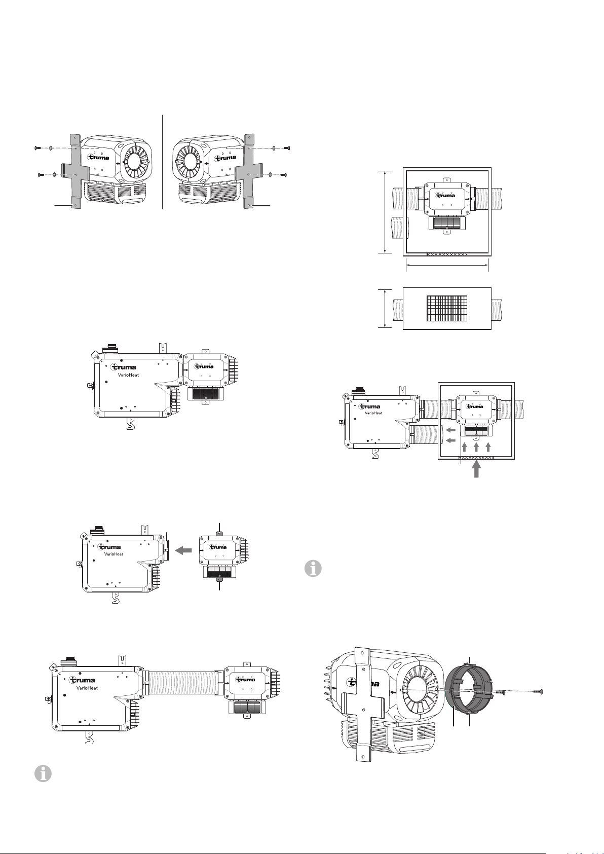
Installation options ............................................................ 4
Attaching to Truma VarioHeat .............................................. 4
Installation in the warm air distribution system .................... 4
Separate installation space ................................................... 4
Installing the Truma E-Kit in the warm air distribution
system ................................................................................... 4
Warm air distribution ........................................................ 5
Connecting duct VR 80 to the Truma E-Kit ........................... 5
Connecting elbow BG 80 to the duct adapter ...................... 5
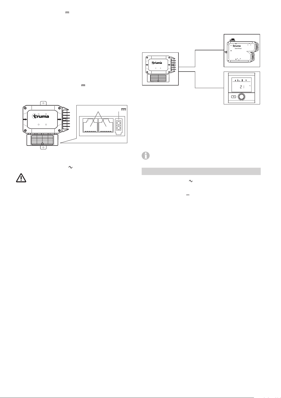
Electrical connection ......................................................... 5
Power supply 12 V ............................................................ 6
Power supply 230 V .......................................................... 6
Controlling the Truma E-Kit ............................................. 6
Function check ................................................................... 6
Technical data ..................................................................... 6


 User manual")


 User manual")