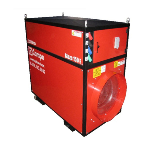
Campo Equipment ECOBlaze DF1600 User manual

CAMPO EQUIPMENT CO. LTD. (ECOBLAZE)
6 Carson Court, Brampton, ON, CANADA, L6T 4P8
Tel: (905) 793-2525 | Fax: (905) 793-8768 | www.campoequipment.com
pg. 1
NG/LP DIRECT FIRED SPACE HEATER: BLAZE DF1600
WWW.CAMPOEQUIPMENT.COM
REPORT # 0367GH009S
Installation Instructions-Manual-Maintenance-Parts List
CAUTION: DO NOT TAMPER WITH HEATER OR ITS CONTROLS. CALL A QUALIFIED SERVICE TECHNICIAN
Retain manual for future reference May 19, 2021
CERTIFIED FOR USE IN CANADA AND THE U.S.A.

CAMPO EQUIPMENT CO. LTD. (ECOBLAZE)
6 Carson Court, Brampton, ON, CANADA, L6T 4P8
Tel: (905) 793-2525 | Fax: (905) 793-8768 | www.campoequipment.com
pg. 2
The heater is designed and approved for use as
a construction heater in accordance with
Standard ANSI Z83.7-2017 • CSA 2.14-2017, UL
733-2013. CHECK WITH YOUR LOCAL FIRE
SAFTEY AUTHORITY IF YOU HAVE ANY
QUESTIONS ABOUT APPLICATIONS.
Other standards govern the use of fuel gases
and heat producing products in specific
applications. Your local authority can advise you
about these.
This manual covers operating instructions,
operator related maintenance instructions,
specifications, and service information. This
manual should be considered a permanent part
of the Blaze DF1600 and must always remain
with the heater.
GENERAL HAZARD WARNING:
FAILURE TO COMPLY WITH THE PRE-
CAUTIONS AND INSTRUCTIONS PROVIDED
WITH THIS HEATER, CAN RESULT IN
DEATH, SERIOUS BODILY INJURY, AND
PROPERTY LOSS OR DAMAGE FROM
HAZARDS OF FIRE, EXPLOSION, BURN,
ASPHYXIATION, CARBON MONOXIDE
POISONING, AND/OR ELECTRICAL SHOCK.
ONLY PERSONS WHO CAN UNDERSTAND
AND FOLLOW THE INSTRUCTIONS
SHOULD USE OR SERVICE THIS HEATER.
IF YOU NEED ASSISTANCE OR HEATER
INFORMATION SUCH AS AN INSTRUCTIONS
MANUAL, LABELS, ETC. CONTACT THE
MANUFACTURER.
WARNING: NOT FOR HOME OR
RECREATIONAL VEHICLE USE.
WARNING: FIRE, BURN,
INHALATION, AND
EXPLOSION HAZARD.
KEEP SOLID COMBUSTIBLES, SUCH AS
BUILDING MATERIALS, PAPER OR
CARDBOARD, A SAFE DISTANCE AWAY
FROM THE HEATER AS RECOMMENDED
BY THE INSTRUCTIONS. NEVER USE THE
HEATER IN SPACES WHICH DO OR MAY
CONTAIN VOLATILE OR AIRBORNE
COMBUSTIBLE PRODUCTS SUCH AS
GASOLINE, SOLVENTS, PAINT THINNER,
DUST PARTICLES OR UNKNOWN
CHEMICALS.

CAMPO EQUIPMENT CO. LTD. (ECOBLAZE)
6 Carson Court, Brampton, ON, CANADA, L6T 4P8
Tel: (905) 793-2525 | Fax: (905) 793-8768 | www.campoequipment.com
pg. 3
FOREWORD
This Operator's Service Manual is intended to
familiarize you with the operation of and
necessary service information for the
BLAZE DF1600 gas fired model. Please read
this manual thoroughly before operating the
Blaze DF1600.
This manual uses the words WARNING,
CAUTION, and NOTE to emphasize certain
information. WARNING identifies personal
safety related information; therefore, be sure to
read the directive because it deals with the
possibility of personal injury. CAUTION
identifies heater-related information; therefore,
be sure to read the directive because it deals
with the possibility of damaging part or parts of
the Blaze DF1600. NOTE identifies
supplementary information worthy of attention.
This manual covers operating instructions,
operator related maintenance instructions,
specifications, and service information. This
manual shouldbe considered apermanent part
of the Blaze DF1600 and must remain with the
heater at thetime of resale. If additional service
information is desired, either contact your local
dealer or write or phone:
CAMPO EQUIPMENT CO.LTD.
(ECOBLAZE)
6 Carson Court
Brampton, ON,
Canada L6T 4P8
Tel: (905)793-2525
Fax: (905) 793-8768
www.campoequipment.com
LIMITED WARRANTY
Campo Equipment CO.LTD and accessories
are warranted to the original retail purchaser.
No warranty is transferable to any subsequent
owner. The warranty period is one year from
the date of purchase. The warranty covers all
defects in material and workmanship insofar as
they are of Campo Equipment CO. LTD,
manufacture. This warranty is limited to the
furnishing of new parts only, in the event the
original part is determined to be defective by
Campo Equipment CO.LTD.
The warranty does not include transportation
costs, labour for inspecting, repairing, or
replacing original parts, or consequential
damages. It also does not cover any damage
because of negligence, accident, misuse, or
abuse. Campo Equipment CO.LTD shall not
be liable for delays caused by defects, for
consequential damages, or for any other
damages, charges, or expenses of any nature.
All parts not manufactured by Campo
Equipment CO.LTD. are warranted insofar as
warranted by the manufacturer of such parts.
SPECIFICATIONS
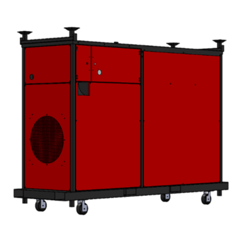
Model Number ..................................DF1600
Width.......................................31.5" (80.01cm)
Length......................................... 92" (233.68 cm)
Height ......................................58.67"(149.02cm)
Weight ..........................992.00 lbs. (449.96Kg)
Supply panel................23.125”x27” (Rectangular)
Blower Motor ........................3.5Hp (2.57 Kw)
Heated Air Output.......9452 CFM (315.42 m³/min)
Manifold Pressure” W.C….….2.5” LP and 5.6” NG
High pressure switch to be adjusted for manifold
pressure
Minimum/Maximum Supply Pressure “W.C…10/14
Pilot Pressure .....................................3.6” W.C
Maximum BTU Input ........................ 1,600,000
Kcal/h .................................................403193.2
Minimum BTU Input LP............................326289
Kcal/h ...................................................822223
Minimum BTU Input NG...........................324538
Kcal/h .....................................................81782
Required Voltage:
208v to 240v 1Phase or 3 phase
Full Load Amps:
1 Phase 14 amps @ 230v
3Phase 8 amps @230v
This unit is equipped with constant voltage
system. It is activated when voltage is lower
than 208v or higher than 240v.
Minimum 4 X 420lb cylinders are to be used.
CAMPO EQUIPMENT CO. LTD. (ECOBLAZE)
6 Carson Court, Brampton, ON, CANADA, L6T 4P8
Tel: (905) 793-2525 | Fax: (905) 793-8768 | www.campoequipment.com
pg. 4
Cylinder supply system must be arranged to
provide for vapor withdrawal from the operating
cylinder. HEATER USAGE
The primary intended use of this heater is to
provide temporary heating for buildings under
construction, alteration or repair.
VENTILATION INFORMATION
DF series heaters require a constant intake
supply of clean, fresh air.
WARNING
The flow of combustion or ventilation air
must not be obstructed in any manner.
WARNING
The heated air MUST NOT be re-circulated
through the heater. The heated work area
must be ventilated to ensure that all air
present in the workspace can be displaced
continuously with fresh heated air.
WARNING
If dizziness or drowsiness is experiencedby
any personnel, evacuate the area. Check
the oxygen level in the heated workspace
and make corrections to the ventilation
system as needed.
CLEARANCE FROM
COMBUSTIBLE MATERIALS
Combustible materials and materials which
give off an explosive or volatile vapor must not
be stored or located in the main discharge air
stream of the heater. Since all materials have
a different flash point, it is imperative that the
discharge air temperature be checked at the
location where any combustible material will be
stored. Make sure the air temperature is well
below the material flash point.
Under no circumstance should any
combustible material be stored in the
airstream within 15 feet (4.57 m) of the air
discharge port or within 6” (15.2cm) of the
top, sides or ends of the heater.
WARNING
This heater must be placed at least 10 Ft
(3.05M) from any LP-Gas Container. The
discharge air stream of this heater must not
be directed toward any LP-Gas container
within 20 Ft (6.1M).
WARNING
Do not use this heater in a space where
gasoline or other liquids having flammable
vapors are stored or used.
CODES
When installing this heater on a job site, the
installation must conform to all local codes or in
the absence of local codes, with the National
Fuel Gas Code, ANSI Z223.1/NFPA 54 and
National Gas and Propane Installation Code,
CSA B149.1 if the unit is to burn natural gas.
The installation must conform to all local codes
or in the absence of local codes, with the
Standard for the Storage and Handling of
Liquefied Petroleum Gases ANSI/NFPA58 and
National Gas and Propane Installation Code,
CSA B149.1 if the unit is to burn vapor propane.
The installation must be inspected prior to the
first start-up of the heater.
LEVELING HEATER
The heater should be installed on a surfacethat
is as level as possible. Insure that the wheels
are locked, and heater does not rock after
leveling the heater. If the heater is not leveled
proper it will not work.
WARNING
Do not block the heater too high of the
ground. Also, use care when leveling the
heater. Keep hands and feet away from any
portion of the heater being raised.

CAMPO EQUIPMENT CO. LTD. (ECOBLAZE)
6 Carson Court, Brampton, ON, CANADA, L6T 4P8
Tel: (905) 793-2525 | Fax: (905) 793-8768 | www.campoequipment.com
pg. 5
WIRING
The required voltage and amperage for each
heater is listed in the SPECIFICATIONS section
of the manual and are also listed on the heater
identification plate attached to the heater. If the
heater needs to be operated on a voltage other
than that indicated by these decals, consult the
factory for instructions. If a voltage change has
been made, re-label the heater as such. For
Safety reasons, as well as preventing damage
to the heater, NEVER leave the wrong decal in
place. No information is better than the wrong
information. The heater must be wired (at every
installation) according to the voltage and
amperage required. A qualified electrician
must wire the heater appropriately
according to the wiring diagram and local,
state, and national codes. The heater must
be electrically grounded in compliance with
the National Electrical Code, ANSI/NFPA 70
and CSA C22.1, Canadian Electrical Code
Part I.
GAS CONNECTIONS AND
SUPPLY
WARNING
Only qualified gas fitting personnel shall
connect or disconnect fuel supply lines to
supply tanks and or gas mains and the
heater gas inlet manifold.
All unions and valves must be checked for
tightness and proper operation before the initial
start-up of the heater. Use Sherlock 5-second
leak (of the proper temperature) or soapy water
on all connections to be sure they are tight.
Replace or tighten any connection as
necessary.
The supply gas hose being used must be
protected from traffic, building materials,
and contact with hot surfaces both during
usage and while in storage.
The supply gas hose shall be visually
inspected prior to each use of the heater. If
it is evident there is excessive abrasion or
wear, or the hose is cut, it must be replaced
prior to the heater being put into operation.
The supply gas hose must be replaced with
a manufacture’s authorized replacement
part only.
See the Service Parts section of this manual
for the appropriate replacement part.
OPERATING GAS PRESSURES
Minimum inlet pressure - 10 inches W.C (0.36
PSI) Maximum inlet pressure –14 inches W.C
(0.50 PSI))
OPERATING INSTRUCTIONS
Pre-Start Checklist
Before attempting to start the Blaze DF1600,
several important checks of the heater and
heater system are critical to safe, efficient, and
dependable usage. Many potential problems
can be avoided by proper maintenance and
attention. The heater should be inspected
before each use, and at least annually by a
qualified service personnel.
1. Familiarize yourself with this Operation /
Service Manual.
2. Check the entire heater for any sign of
physical damage.
3. Check for obstructions to the air intake and
discharge of the heater. Remove anything
that will obstruct or restrict airflow. The
heated work area must be ventilated to
ensure that all air present in the workspace
can be displaced continuously with fresh
heated air. The heater air intake must be
supplied with clean, fresh outside air
always.
4. Check incoming voltage.
5. Check the entire heater for loose nuts,
bolts, and electrical connections. Be sure
the blower mounting bolts are tight.

CAMPO EQUIPMENT CO. LTD. (ECOBLAZE)
6 Carson Court, Brampton, ON, CANADA, L6T 4P8
Tel: (905) 793-2525 | Fax: (905) 793-8768 | www.campoequipment.com
pg. 6
6. Check Flame Rod to be sure it is clean.
(See Maintenance section of this
Manual.)
7. Check that the gas type and inlet pressures
agree with that stated on the DF1600
Identification Plate. This plate may indicate
both Natural Gas and LP.
8. Check all unions and valves for tightness
and proper operation. Tighten or replace
as necessary. Use Sherlock 5-second leak
(of proper temperature) or soapy water on
all NEW connections to be sure they are
tight.
9. Service and make all adjustments before
starting heater.
10. All area surrounding the heater must be
kept clear and free from combustible
materials, gasoline and other flammable
vapors and liquids.
Starting Heater
NOTE: Do all items in the PRE-START
CHECKLIST before starting the heater.
ATTENTION: Gas and electrical connections
must conform to all local area codes.
1. Check Heater Identification Plate and decals
for correct supply voltage and phase.
WARNING
Only a qualified electrician shall connect or
disconnect all electrical power cords.
CAUTION: Power supply cord must be
adequate for total unit power requirements and
distance to primary power source.
2. This appliance receives 1 Phase or 3 Phase
208 to 240 V supply must be available.
INSTALLATION:
Single Phase
Three Phase
Up to 100’ 3 # 6
Up to 100’ 4 # 8
Up to 200’ 3 # 4
Up to 200’ 4 # 6
Up to 300’ 3 # 3
Up to 300’ 4 # 4
NOTE: To power up the heater inside the
power supply compartment there are four CAM
locks and a 3 Phase, 250V, 30 Amp male plug,
use either one of them. When using the plug
make sure that the CAM locks have caps on
them. The main power switch should be in the
“OFF” positions. This power source must
include a “Short Circuit” protection device such
as a circuit breaker or fusible.
With all connections secure, including grounds,
energize the heater. Place the main power
switch to on position that should illuminate the
green neon light and should energize the RTC
DFC+ Controller.
WARNING
Only qualified gas fitting personnel shall
connect or disconnect fuel supply lines to
supply tanks and or gas mains and the
heater gas inlet manifold.
Note: Do not attempt to manually light the
pilot.
1. Connect fuel supply line to manifold inlet.
Turn on the gas supply at source and check
for leaks at all connections.
2. Open all valves between fuel supply and
gas manifold inlet valve, and then open gas
manifold inlet valve.
3. Place the heat/Fan switch to “HEAT”
position if running without thermostat and if
running with the thermostat leaving the
heat/Fan switch to ‘HEAT’ position plug in
the thermostat in to the remote stat
receptacle. Then blowerwill start and purge
the unit for a pre-set time (2-5 sec.) before
the ignition sequence will begin.
4. Once the pilot flame has been established,
the main flame will come on and will begin
to adjust as needed to maintain the
discharge air temperature at the pre-set
temperature.
NOTE: Air may be trapped in the gas supply
line and the gas manifold. A second or third
trial for ignition may be necessary to purge all
the air from the system. If a flame is not
established during the first trial for ignition.

CAMPO EQUIPMENT CO. LTD. (ECOBLAZE)
6 Carson Court, Brampton, ON, CANADA, L6T 4P8
Tel: (905) 793-2525 | Fax: (905) 793-8768 | www.campoequipment.com
pg. 7
Simply turn of the main switch and turn it back
on that would reset the entire system.
5. The DFC+ will always display the current
discharge air temperature. Press any arrow
key to change the discharge setpoint
temperature. Once an arrow key is pressed,
the LED will display the text for the current
setpoint temperature. Use the down or up
key to set a new discharge temperature,
then press the middle key to save the
changes made. If a key is not pressed for 10
seconds, the DFC+ will exit without saving.
When adjusting the set point range, the set
point cannot surpass the set Low and High
values. That is 120°F to 250°F.
WARNING
If unit fails to ignite or function properly;
disconnect fuel and power supplies and
contact authorized service personnel.
NOTE: If the blower does not turn on, check
the control braker (The “Power” indicator light
will confirm that the control braker is good) or
make sure the VFD is energized.
NOTE: Placing the Main switch in the “OFF”
position will automatically reset the heater if the
control is in a lock out condition. If the burner
still does not ignite, use the following sequence
of steps:
1. Make sure the gas pressure is adequate.
2. Check to make sure all manual valves are
open between the fuel source and the
burner.
3. Check to make sure the proper voltage is
supplied to the heater.
WARNING
A qualified electrician must make the
adjustments.
4. Check to be sure the air proving switch
sensor tubes are clear of any obstructions.
NOTE: Listen to hear the pilot solenoid valve
click. If the click is not heard,the solenoid valve
may not be opening and may be defective.
Sparking should also be present at the spark
igniter in the burner If the click is heard and
pressure is registered, move the main switch to
the “OFF” position and place the Heat/Fan
switch in the “center” position. Lockout power
to the heater and check the following:
1. Check the igniter for corrosion and proper
separation. Be sure the insulator is not
cracked and is properly seated in the
burner. Check the connections for clean,
dry, and tight contact. Check the ignition
wire for cuts and cracks that may allow the
spark voltage to jump to ground before the
igniter. Also check that the ignition wire is
securely fastened to the ignition
transformer high voltage terminal.
2. Check the burner ports for obstructions.
Remove any obstruction.
3. Check the electrical system including
wiring, connections, switches, and major
electrical components.
4. Check the input voltage and phase to the
heater; adequate voltage and proper phase
is necessary for proper function.
5. Restore power to the heater and place the
Main switch in the "ON" position then place
the Heat/Fan switch to ‘HEAT’position and
allow the heater to go through its start up.
NOTE: If the burner does not ignite after the
start up, see TROUBLESHOOTING section.
NOTE: The thermostat must be set above
ambient.
Stopping Heater
NOTE: if the heater is being stopped for an
extended period.
1. Turn manual inlet valve to OFF position.

CAMPO EQUIPMENT CO. LTD. (ECOBLAZE)
6 Carson Court, Brampton, ON, CANADA, L6T 4P8
Tel: (905) 793-2525 | Fax: (905) 793-8768 | www.campoequipment.com
pg. 8
2. Place Main switch to “ON” position and
Heat/Fan switch to “FAN” position as well.
3. Allow the heater to cool down for several
minutes; then place the Main switch and
Heat/Fan switch to “OFF” position.
4. Turn off the gas supply at the LP-Gas
cylinder or gas main inlet when the heater
is not in use.
Extended Storage
If the heater is to be shut down for an extended
period, the fuel lines should be cleared from the
primary source to the burner. Clear the lines
by (with the heater running) closing the valve at
the primary source and allowing the heater to
draw the pressure out of the lines. Allow the
pressure to bleed out of the lines until the
burner stops; then place the Main Switch in the
“OFF” position. Close all manual valves.
Disconnect all power and fuel supply lines and
cover all air and fuel line openings.
CAUTION: Never close manual valves at the
primary source and heater inlet at the same
time unless all fuel has been bled out of the
lines. Fuel trapped between the primary
source and the heater in the supply lines will be
subjected to expansion dependent upon
ambient air conditions. Excessive pressure
build-up could occur in the supply line and lead
to line failure. Consult your local gas supplier
for proper piping and gas codes.
When storing the heater indoors the gas
connection between the heater and the
supply cylinder must be disconnected.
Preparing After Extended Storage
Several days or weeks before the heater will be
used, attention should be paid to properly
preparing the heater for service. Since the
heater is an important element of your
operation, it only makes sense that a certain
amount of time is necessary to prepare the
heater. The DF1600 should be inspected
annually by qualified service personnel.
WARNING
Make sure the heater is de-energized before
servicing.
1. Check the igniter for corrosion, damage,
(cracked insulator, etc.), and proper
separation. Make sure that it is secure in
the burner. Replace any igniter beyond
repair.
2. Check the burner gas ports for corrosion
and any obstructions. (See burner
Maintenance Section for cleaning
instructions.)
3. Check the flame rod to be sure it is clean.
Remove any scale or build-up of foreign
matter.
4. Check for wax buildup in the manifold lines.
5. Check the wiring for broken wires or loose
connections. Tighten or replace as
necessary.
6. Check the entire heater for any visual
damage. Repair or replace any damaged
components.
7. Check all unions and valves for leakage or
damage. Tighten or replace as necessary.
8. Do all items in the PRE-START
CHECKLIST; then start the heater to
ensure proper operation.
Control Functions and
Applications
Switches and Devices:
MAIN SWITCH
ON Position: POWER TO RTC DFC+ & VFD
•Activates the VFD and supplies power
to control circuit
OFF Position: POWER OFF
•Turns off the power of entire heater.

CAMPO EQUIPMENT CO. LTD. (ECOBLAZE)
6 Carson Court, Brampton, ON, CANADA, L6T 4P8
Tel: (905) 793-2525 | Fax: (905) 793-8768 | www.campoequipment.com
pg. 9
HEAT/FAN SWITCH TO FAN
FAN/RIGHT Position: FAN ON
•Activates the fan and supplies power to
control circuit.
CENTRE Position: TURN FAN OFF
•Turns off the fan.
HEAT/FAN SWITCH TO HEAT
HEAT/LEFT Position: BURNER ON
•Activates the burner circuit & fan.
CENTRE Position: STOP’s the burner and
cuts off the fan limit opens.
Belimo and RTC Modulating System
and DFC+ Integrated Gas Fired Heating
control
This system is made up of 3main components,
a variable gas valve or regulator, a discharge
air temperature sensor, and an amplifier
(DFC+) to control them all.
The discharge air temp sensor is mounted in an
air mixing tube, located near the discharge air
side of the heater. Its function is to provide
temperature information to the amplifier
(DFC+). This information is used by the
amplifier to control the “MAX” air temp portion
of the amplifier.
The Belimo or RTC Modulating System
provides for continuous, steady heat, at the
rate required. It does not stop the heater at any
time.
The modulator is the device that does the
actual increasing and decreasing of gas flow to
the burner. An electromagnet controls how
much gas can pass through the modulator. The
more voltage that is applied to the magnet, the
more gas that can pass through. The modulator
is typically full open when a voltage of about
24-volts DC is applied from the amplifier.
Minimum flame results from zero volts DC. The
DF1600 heater has a minimum BTU input
rating of 324538 BTUs on NG (81782 Kcal)
and 326289 BTUs (82223 Kcal) on LP.
The Belimo Modulating System has been
pre-set at the factory to insure this input.
No field adjustment of this set point is
required.
Conventional Remote Thermostat
The optional remote thermostat (if used)
connects to the remote thermostat receptacle
on the heater. The difference is that when this
device is used, the heater delivers a constant
high temperature which is set on the SP of the
RTC DFC+ Controller, until the set temperature
on the conventional thermostat is reached. At
that time, the heater goes to 120°F and keeps
the temperature balanced until the temperature
at the thermostat falls below the set
temperature. The heater then goes back to the
thermostat mode delivers high temperature air.
To use this device, select and position the
thermostat at a location that will represent a
good average room temperature inside the
structure to be heated that will not be directly
affected by the heated air discharge from the
heater. Route the plug end of the cord to the
heater and plug into the special receptacle
located on the heater control panel.
The thermostat assembly comes with a 50-foot
cord with a plug, as standard.
The adjustment range is from 40° to 110° F. (5°
to 43° C.). To use the thermostat, plug in the
remote thermostat to the designated REMOTE
STAT receptaclethen dial upor down or setting
it to the desired room temperature to be
maintained.
MAINTENANCE
WARNING
For your own safety, Lockout electrical
power before attempting any service
procedures to prevent accidental start-up.

CAMPO EQUIPMENT CO. LTD. (ECOBLAZE)
6 Carson Court, Brampton, ON, CANADA, L6T 4P8
Tel: (905) 793-2525 | Fax: (905) 793-8768 | www.campoequipment.com
pg. 10
Burner
Proper maintenance of the burner is critical for
efficient trouble-free operation. The burner of
every Campo heater is tested before shipment,
however, changes in altitude, fuel,
temperature, and humidity will affect the
performance and efficiency of the burner. Also,
the burner should be checked at least annually
(preferably before the start of the heating
season) for efficient burning.
1. Shut the system down totally,
disconnecting or locking out power supply
so there can be no accidental start-up
during inspection.
2. Inspect the burner carefully, including
upstream and downstream sides of mixing
plates as well as burner body face. Any
accumulation of scale or foreign material on
either side of the mixing plates should be
removed with a wire brush. Check visually
that no holes in the mixing plates are
blocked. If any burner ports are plugged
(even partially) clear them with a piece of
wire or a #47 drill bit (2mm).
WARNING
Do not enlarge burner ports or performance
may be drastically affected.
If any mixing plates are loose or missing
fasteners, tighten/replace as necessary.
Always use zinc plated or stainless fasteners.
3. Observe flame pattern and, if necessary,
take steps to correct obstructed ports. The
velocity and distribution of the air across
the burner is pre-set at the factory and
should be changed by authorized service
personnel only.
Igniter
To start ignition, the igniter must be adjusted
properly and must not be damaged or
defective. Periodically the igniter should be
inspected for damage, corrosion, and
separation. To inspect and adjust the igniter,
use the following procedure:
1. Remove the igniter from the burner.
2. Visuallyinspect the igniter for corrosion and
damage to the insulator and tip.
3. Consult the Specification Sheet for proper
spacing and position.
Pressure Regulator
WARNING
Unqualified service personnel must not
make any adjustments on the regulators!
The pressure regulator on the manifold
functions to reduce the supply of gas to the
burner. There is one pressure regulator on the
main line.
To adjust the main line regulator pressure,
remove the cap of the regulator; then either
turn the adjusting screw out to decrease
pressure or turn the adjusting screw in to
increase pressure. Do not make any
adjustment on the regulators without knowing
what you are doing and having the proper
gauges attached. Also, do not bottom the
adjusting screw.
The heater is designedto operate with a line
pressure upstream of the Maxitrol RV81, of
10 to 14 W.C. (2.24kPa to 3.48kPa). For
maximum efficiency and safety, the
regulator must not be adjusted above this
pressure. The Belimo or RTC modulating
valve varies the gas flow of gas to the
burner to maintain the pre-set discharge air
temperature and has been set at the factory
for optimum performance. Field
adjustments are not required.
CAUTION: Damaged or defective regulators
must be replaced. Also, never exceed the
pressure specifications listed.

CAMPO EQUIPMENT CO. LTD. (ECOBLAZE)
6 Carson Court, Brampton, ON, CANADA, L6T 4P8
Tel: (905) 793-2525 | Fax: (905) 793-8768 | www.campoequipment.com
pg. 11
TESTING ELECT. COMPONENTS
Common sense and careful thought can make
troubleshooting of electrical problems much
less complicated. Remembering that electricity
must have a completed path for it to work is the
first necessary understanding. Secondly,
search for the problem by looking at the most
obvious solution first; then look toward the
more complicated solutions. Use the
appropriate wiring diagram as a guide for
isolating the problem.
If ignition problems of the burner are
encountered, for instance, use the following
example as a guide.
1. Check the breakers and switches.
2. Check gas supply lines and manual valves,
and fuel availability.
3. Check for proper output voltage from power
source.
4. Check to be sure all wire connections are
tight.
5. Remove the electrode and check its
condition. If worn, replace. If improperly
adjusted, adjust the separation and
extension to within specifications.
The following is the method for testing major
electrical components.
WARNING
A qualified electrician should perform all
tests, replacements, and adjustments.
Testing the Main Switch
Before assuming the Control Switch to be
defective, check the breaker to be sure it is
good. Secondly, be sure to check the wiring
connections and wires to be sure the
connections are tight, and wires are good.
Remember that the blower must be operating
properly for the burner to operate. The switch
can be tested using an ohmmeter.
To test, use the following procedure:
1. Disconnect the main power supply, open
the Electrical Compartment.
2. Set the ohmmeter in the continuity test
mode.
3. With the main switch in OFF position, place
one tester lead on the common contact and
one tester lead onthe contact relative to the
switch position. Place the switch to “ON’
position. The meter must show continuity.
4. With the HEAT/FAN switch in ‘HEAT’
position, place one tester lead on the
common contact and onetester lead on the
contact relative to the switch position. The
meter must show continuity on the relative
contact.
Intermittent Pilot Gas Ignition Control
• Natural or LP gas
• Pilot burner ignition using an external ignitor
• Flame rectification circuit to monitor flame
presence.
• Monitoring of 120V, pilot, and main gas valve.
• Five LED indicators for:
•Running interlock
•Recycle/airflow
•Trial for ignition
•Flame
•Alarm
WARNING
Never touch the flame rod or the wire
leading to it while power is ON. The
amplifier charges the flame rod with
approximately 300 volts AC. Serious
personal injury could result!
Testing Air Pressure Differential Switch
The DF1600 uses an air pressure differential
switch to confirm that the main blower is
moving enough air through the heater.
This switch must be activated before the burner
will ignite. The switch senses the difference
between the velocity developed by the blower.
Any restrictions beyond the set point limit
of the switch to the inlet of the heater will
cause the switch to open and shut the

CAMPO EQUIPMENT CO. LTD. (ECOBLAZE)
6 Carson Court, Brampton, ON, CANADA, L6T 4P8
Tel: (905) 793-2525 | Fax: (905) 793-8768 | www.campoequipment.com
pg. 12
burner off. All discharge duct work must be
removed before testing the switch.
1. Check the sensing tube from the "HIGH"
port on the switch body to the port right
under the switch for kinks or obstructions.
Insure the sensing line is connected to the
switch. The “HIGH” port sensing tube is
located perpendicular and facing into the
air stream.
2. To test if the switch is functioning,
disconnect and insulate wires leading to the
switch N.O. contacts. Connect an
ohmmeter or continuity light to the switch
N.O. contacts. Placethe Heat/Fan switch to
“FAN” position. The ohmmeter should read
low resistance or the continuity light should
come on. When the blower is stopped the
light should go out and the resistance
reading should be high. If the contacts
remain closed regardless of the blower
status, the air switch must be replaced.
Contact the factory in the event the
switch must be replaced. Only factory
authorized personnel can replace and
calibrate the air switch.
Testing High Limit Switch
The High limit switch is a solid-state device.
When the output contacts are operating
properly, the limit switch will allow the heater to
run when the Heat/Fan switch is placed in the
“Heat” position, as long as the air temperature
at the limit sensor is below the “HIGH LIMIT
that is 150°F”.

CAMPO EQUIPMENT CO. LTD. (ECOBLAZE)
6 Carson Court, Brampton, ON, CANADA, L6T 4P8
Tel: (905) 793-2525 | Fax: (905) 793-8768 | www.campoequipment.com
pg. 13
TROUBLESHOOTING
NOTE: Before replacing any component, test according to instructions in this manual. This
trouble shooting guide will say replace, but replacement should occur only after appropriate
testing.
TROUBLESHOOTING DF1600 DIRECT FIRED HEATER
PROBLEM
CONDITION
REMEDY
Blower Motor does not
run. (Blower mode)
1. No current to heater.
1. Turn breaker –safety switch
ON.
2. Voltage insufficient
2. Check incoming supply.
3. Wiring –connections
disconnected –loose –
broken.
3. Connect –tighten –replace
wiring connections.
4. Main Switch OFF –Defective.
4. Turn Control toggle Switch
ON –replace Switch.
5. Defective VFD.
5. Check to see if there is power
to the VFD.
Burner does not ignite.
1. Voltage insufficient.
1. Check incoming supply.
2. Electrode –disconnected –
adjusted incorrectly –
defective.
2. Connect –adjust - replace
electrode.
3. Air Proving Sw.
Disconnected –defective.
3. Connect –Replace Air
Proving Sw.
4.Tilt switch Disconnected, or
Unit is not on a level surface or
defective.
4. Connect—Replace Tilt Switch
or Level the Unit.
5.Fan Over heat switch is open.
5. Check to see if the unit is not
running on low voltage or fan
is not over heating.
6. Insufficient Gas delivery.
6. Fill tank –open valves –
replace solenoid valves.
7. Regulators adjusted incorrectly
–defective.
7. Adjust –replace regulators.
8. Burner gas ports –obstructed
–damaged.
8. Clean ports –replace burner.
9. Flame sensor –damaged –
defective.
9. Replace Flame Sensor.
Burner stops during
usage.
1. Heater overheating.
1. Check to see if modulating
valve is not stuck.
2. Power interrupted.
2. Restore power.
3. Gas Burner ports obstructed.
3. Clean –replace burner.

CAMPO EQUIPMENT CO. LTD. (ECOBLAZE)
6 Carson Court, Brampton, ON, CANADA, L6T 4P8
Tel: (905) 793-2525 | Fax: (905) 793-8768 | www.campoequipment.com
pg. 14
4. Air proving switch defective.
4. Replace Air Proving Sw.
5. Flame rod dirty –defective.
5. Clean, Replace Flame Rod.
6. Inadequate fuel delivery.
6. Fill Tank –replace regulators,
valves –check gas lines for
obstructions.
TROUBLESHOOTING DF1600 DIRECT FIRED HEATER
PROBLEM
CONDITION
REMEDY
Heater overheating
1. Gas pressure excessive.
1. Adjust –replace regulator.
2. RTC Discharge
Temperature Sensor
defective.
2. Replace sensor,
troubleshoot modulation
system.

CAMPO EQUIPMENT CO. LTD. (ECOBLAZE)
6 Carson Court, Brampton, ON, CANADA, L6T 4P8
Tel: (905) 793-2525 | Fax: (905) 793-8768 | www.campoequipment.com
pg. 16
Service parts
Part #
Description
C70061
ON/OFF DISCONNECT YELLOW SWITCH BASE 32 AMP
C80033
ON/OFF DISCONNECT YELLOW SWITCH HANDLE
C70062
ON/OFF DISCONNECT SHAFT EXTENSION
C50263
2 POLE 32A BREAKER
C50264
1 POLE 32A BREAKER
C80181
2A 2P BREAKER
C80182
4A 1P BREAKER
C80183
150VA 208/230V - 120V XTMR. TRANSFORMER
C20023
Toggle Switch
C78889
Digital Panel Mounted Voltmeter
C70064
3 POSITION SWITCH
C70069
FIXING COLLAR
C70067
N.O. CONTACT BLOCK
C70028
VFD
C70137
R Fan 500
C90025
Power On Indicator Light GREEN
C90029
Outlet for Plug
C70052
TILT SWITCH
C82036
Spark Controller
C80186
MAIN CONTROLLER
C82163
Actuator ball valve 11/2" NPT
C80916
12" Discharge Air-tube
C60139
Temperature Sensor c/w Stew
C82164
Bracket Assy Kit 1/2"
C82165
MODULATING ACTUATOR
C60136
1/4" ASCO Pilot Valve
C82037
120V Solenoid Valve
C50155
AIR SWITCH
C90041
High Limit Switch
C90037
Fan Over-ride Switch
C82038
MALE FLANGE INLET
C70046
TERMINAL BLOCK
C70048
TERMINAL BLOCK END STOP
C70047
TERMINAL BLOCK END PLATE
C70072
Flip lid cover housing
C82043
GAS IGNITOR
C50131
Black Cam Lock

CAMPO EQUIPMENT CO. LTD. (ECOBLAZE)
6 Carson Court, Brampton, ON, CANADA, L6T 4P8
Tel: (905) 793-2525 | Fax: (905) 793-8768 | www.campoequipment.com
pg. 17
C50132
Red Cam Lock
C50133
Blue Cam Lock
C50134
Green Cam Lock
C82044
CAM LOCK CAPS BLK
C82045
CAM LOCK CAPS RED
C82046
CAM LOCK CAPS BLUE
C82047
CAM LOCK CAPS GREEN
C82048
MIDCO BURNER 3FT.
C80117
1.5" X 6" Pipe Nipple
C82049
1 1/2 x 4 nipple
C80121
1.5" X 3" Pipe Nipple
C80115
1.5" X 2" Pipe Nipple
C80114
1.5" Elbow
C80124
1.5" Street Elbow
C80123
1.5" Union
C82050
1 1/2 x 1 1/2 x 3/4 T section
C82051
3/4 to 1/4 reducer
C60143
1" 1/2" X 1/4" Nipple
C82052
1/4 elbow
C80913
1/4" NPT x 1/4" 90 component male elbow
C82053
1 1 /2" MAIN VALVE
C82054
Maxitrol Pressure Regulator
C82055
1 1/2" ASCO Solenoid Valve
C60137
1/4' Maxitrol pressure regulator
C60129
57.5" Copper Tubing
C50251
High Pressure Switch
C70041
RELAY
C70042
RELAY BASE
C82057
HEATER FRAME
C82058
PANEL
C82059
TOP COVER
C82060
BURNER SHROUD 1
C82061
BURNER SHROUD 2
C82062
BURNER SHROUD FRONT PLATE
C82063
PANEL
C82064
TRAIN DOOR
C82065
ELECTRIC DOOR RIGHT
C82066
ELEC DOOR LEFT
C82067
CAN LOCK PLATE
C80021
MOUNT BRKT (TILT SWITCH)

CAMPO EQUIPMENT CO. LTD. (ECOBLAZE)
6 Carson Court, Brampton, ON, CANADA, L6T 4P8
Tel: (905) 793-2525 | Fax: (905) 793-8768 | www.campoequipment.com
pg. 18
C82069
PANEL ASSEMBLY
C82070
ELECTRIC PANEL FRONT ASSEMBLY
C82071
CONTROL BACK PLATE ASSEMBLY
C82072
Louver bar
C60190
Louver Plate
C82074
RECEPTACLE BOX
C82075
ADAPTER PLATE
C82076
WIRE CHANNEL
C82077
INNER BURNER SHROUD 1
C82078
INNER BURNER SHROUD 2
C82079
BURNER SHROUD BRACKET SMALL
C82080
R 500 MOUNT ASSY
C82081
BURNER SHROUD BRACKET LONG
C82082
BURNER SHROUD BRACKET BOTTOM
C82083
BURNER SHROUD TOP BRACKET
C82084
SUPPLY PANEL RECTANGULAR ASSY
C82087
Serial Number (variable data)
C82088
Warning-Use with Propane or Natural Gas Only
C82090
Caution-supply cord
C82091
Caution-door panel-closed
C82092
caution- adequate ventilation
C82093
General Hazard Warning
C82094
Warning Max Inlet Pressure
C82095
Position Heater Properly before use
C82096
Wiring Diagram
C82097
DF 1600 logo
C82098
Decal-Campo Logo 16.50"
C82099
Decal - Train Compartment
C82100
Decal - Electrical Control Panel Compartment
C82101
Decal - Power Supply Compartment
C82102
Decal - Power Supply Instructions
C82103
Buttons
C82166
Decal - Ductwork
C82104
Complete Kit DF1600
C82085
E 500 FAN MOUNT ASSY
C82086
E 560 FAN MOUNT ASSY
C82111
1 1/2" BUTTERFLY VALVE
C82112
2-10V MODULATING ACTUATOR
Table of contents
Other Campo Equipment Heater manuals

Campo Equipment
Campo Equipment ECOBlaze 200D Turbo User manual

Campo Equipment
Campo Equipment BLAZE 1.5E User manual

Campo Equipment
Campo Equipment BLAZE 150E User manual

Campo Equipment
Campo Equipment ECOBlaze DF2500 User manual

Campo Equipment
Campo Equipment BLAZE 9E User manual

Campo Equipment
Campo Equipment Blaze EB400G User manual
Popular Heater manuals by other brands

Gude
Gude GID 20 Translation of the original instructions

Adler Europe
Adler Europe AD 7725 user manual

Real-El
Real-El HEAT-L210 Operation manual

Optimum
Optimum OS-1609 operating instructions

Superior Radiant
Superior Radiant TA series Installation, operation and service instructions

Mi-T-M
Mi-T-M MH-0070-0M10 Operator's manual