5
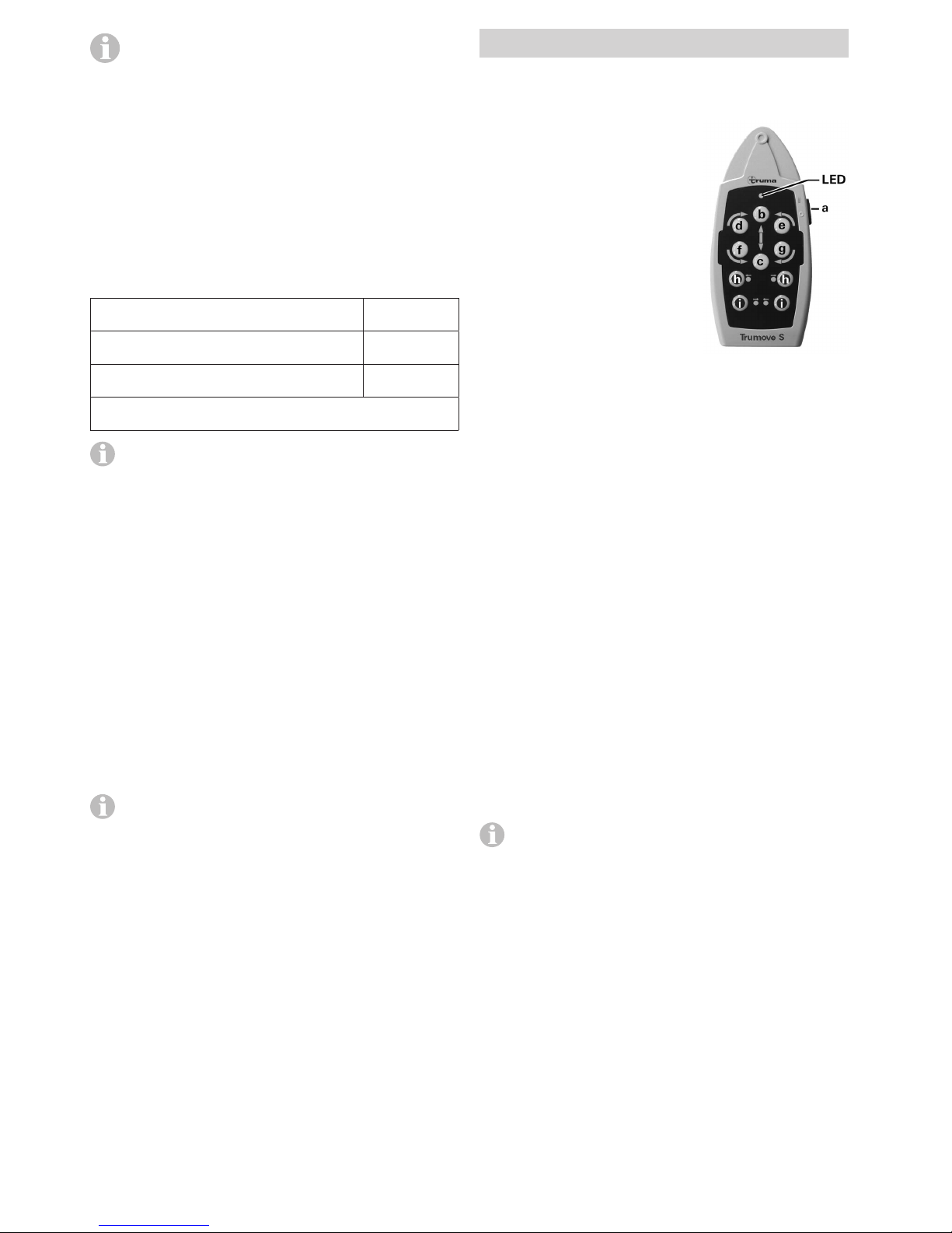
Remote control LED flash codes and acoustic
signal
LED “On” and no acoustic signal
System is ready for operation
LED “Off” and no acoustic signal
System off (check remote control batteries if necessary)
LED “flashes” in combination with acoustic signal
– for approx. 5 seconds after switching the remote control on,
until the system is ready for operation.
– for approx. 10 seconds after switching the remote control
on, then it is switched off again – 7-pin or 13-pin safety plug
not connected to safety socket or unable to establish radio
link to controller.
– every 3 seconds if the caravan battery has a low charge (fin-
ish manoeuvring as quickly as possible and charge battery).
– 5 times per second (5 Hz) if the caravan battery voltage is
low. No manoeuvring is possible until the battery voltage
is above 11 V again (e.g. by means of recovery / battery
charging). The drive rollers can also be disengaged with a
voltage of less than 11 V.
– approx. 2 times per second with overcurrent / overtempera-
ture (2 Hz). Switch remote control off and on again (wait for
cooling down if necessary in the event of overtemperature).
Changing the batteries in the remote control
Please be sure to use leak proof micro-
batteries only, type LR 03, AAA, AM 4,
MN 2400 (1.5 V).
When fitting new batteries
ensure the polarity is correct!
Dead and used batteries may
leak and damage the remote
control! Remove the batteries if the re-
mote control is not going to be used for
an extended period.
Fig. 3
No claims under guarantee will be considered for dam-
age caused by leaking batteries.
Before throwing away a defective remote control, it is essen-
tial that the batteries are removed and disposed of in a proper
manner.
Manoeuvring the caravan
Please read the “Safety instructions” before using
the Trumove S / T!
Apply handbrake with caravan uncoupled.
Unplug 7-pin or 13-pin plug from vehicle and plug into safety
socket of caravan.
For safety reasons the Trumove S / T can only be oper-
ated if the 7-pin or 13-pin plug of the caravan has been
plugged into the safety socket.
In the event of an error, the 7-pin or 13-pin plug should
not be removed from the safety socket as otherwise the
electronic protection function is deactivated.
If there is a fault in both caravan brake lights, the power
circuit of the safety socket is not closed. In this case the
Trumove S / T cannot be operated.
Switch remote control on – green LED flashes for 5 seconds
in combination with the acoustic alarm until the control unit is
ready for operation.
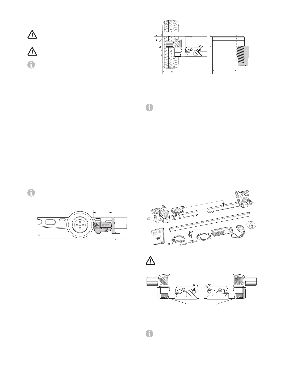
Simultaneously press the two buttons (h) for engaging, which
starts after approx. 3 seconds (safety delay).
Use the position indicator to check whether both drive
rollers have been correctly applied (arrow of yellow posi-
tion indicator is above the line that is closest to the tyre).
Before operating the Trumove S / T, release the
handbrake.
The six direction buttons provide movement in six directions
–forward, reverse, left forward, left reverse, right forward,
right reverse.
With the Trumove S the “left forward” (e) and “right reverse” (f)
or “right forward” (d) and “left reverse” (g) buttons can also
be pressed simultaneously in order to turn the caravan in a
circle on the spot without moving it forwards.
The soft start / stop facility means that the caravan starts
without jerking and is gently braked when stopping.
If the buttons are released or the radio signal is interfered with
or becomes too weak, the caravan stops. Your Trumove S / T
cannot be activated by radio devices or other Mover® remote
controls.
After starting up, the Trumove S / T moves at a uniform speed.
The speed will increase a little when going downhill and de-
crease a little when going uphill.
After manoeuvring, first apply the handbrake and then
disengage the drive rollers from the tyres.
Move slide switch on remote control to the “Off” position
to switch the remote control and the Trumove S / T off.
The slide switch also acts as an “Emergency stop”
switch.
Remove plug from safety socket after manoeuvring, otherwise
the battery will be discharged. Standby current with plug
inserted approx. 200 mA.
Coupling to a towing vehicle
It is possible to position the caravan’s coupling to a stationary
car tow ball using the Trumove S / T, but take some care.
Use the instructions above as your guide. Use the button
controls to bring the caravan to the car (car handbrake “ON”,
and car in gear). Use a button stabbing technique to exactly
position the coupling directly over the ball. Lower the coupling
to the ball and engage in the normal way using the jockey
wheel.
Prepare the caravan for towing as usual. The caravan must
never be towed with the drive rollers engaged.
Maintenance
Please do not allow the drive units to become soiled with
coarse road material. When you are cleaning the caravan,
spray the Trumove S / T with a water hose to dissolve mud
etc. Please ensure that no stones, twigs or the like become
trapped in the equipment. The control unit does not require
maintenance. Please keep the remote control in a dry place.
Every year (and / or before putting away for the winter), clean
Trumove S / T as described, dry and lightly spray the drive unit
guides with oil spray or a similar water-repelling lubricant. Do
not put lubricant on the rollers or the tyres! Engage and
disengage the drive units several times to allow the lubricant
to penetrate all the guides. Do not park the caravan with the
drive rollers engaged.