www.trumbull-mfg.com
Trumbull Manufacturing
3850 Hendricks Road, Youngstown, Ohio 44515
Phone:
330.270.7888
Toll Free:
877.504.1507
Fax:
330.392.0756
i
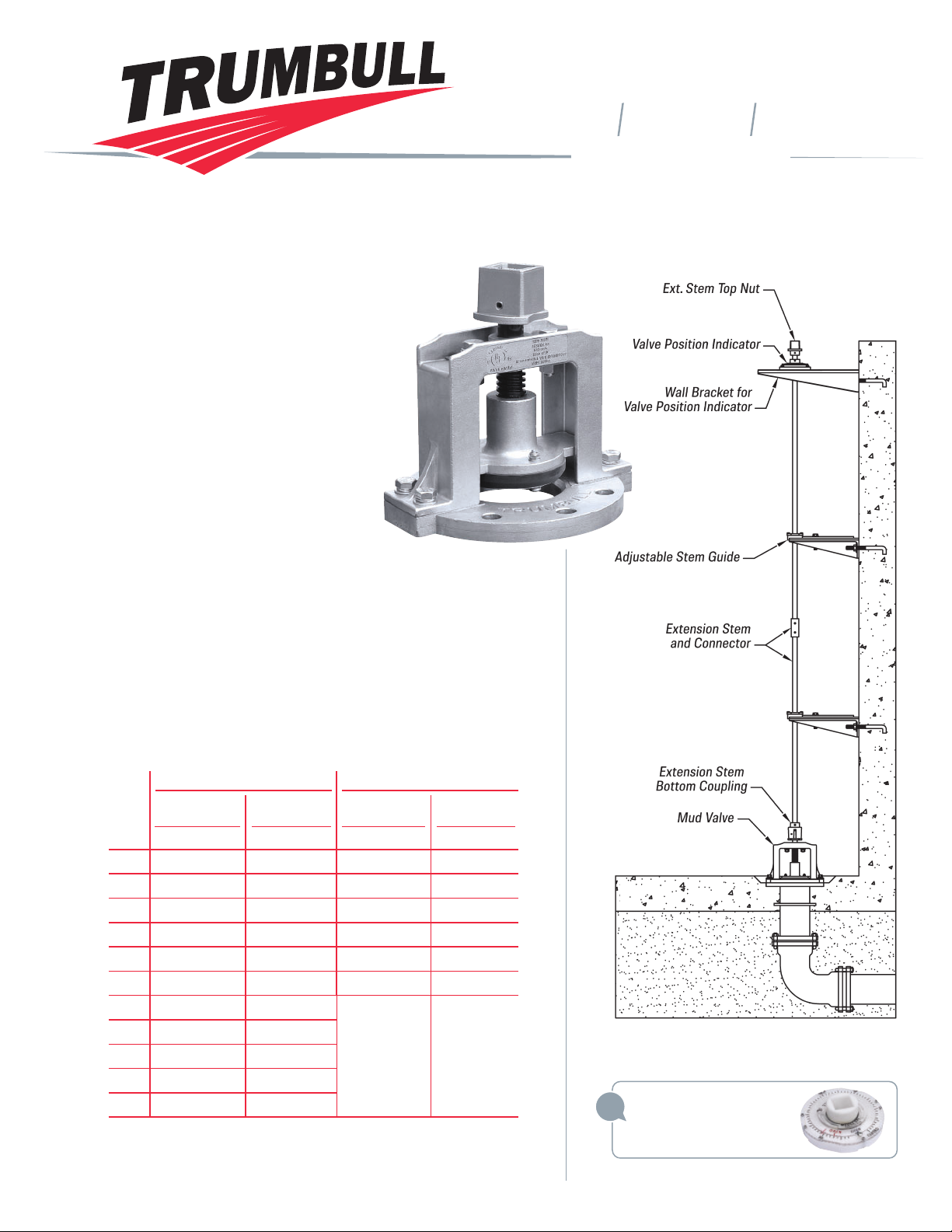
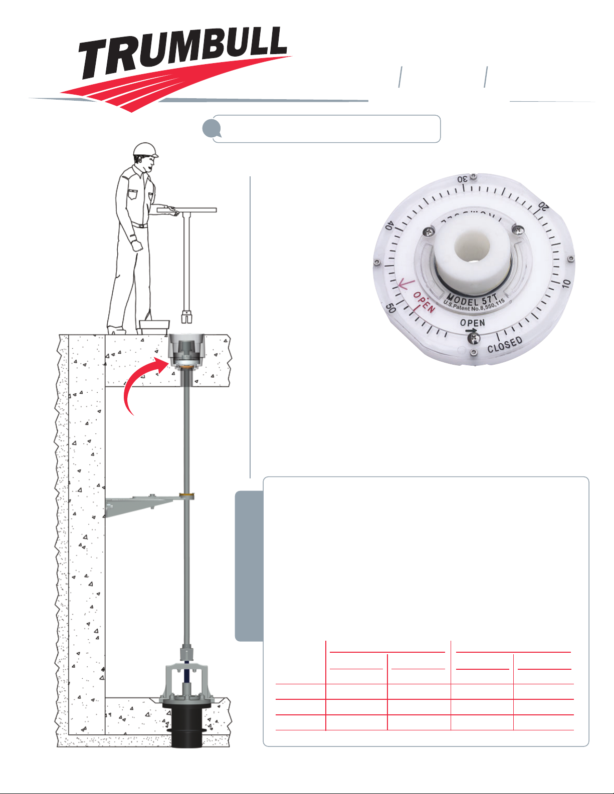
Typical Mud Valve Installation
See page G-34 for installation options.
Valve Position Indicators
recommended on all Mud
Valves (see page F-9).
Size Item №Item №Item №Item №
3”1367-1349 367-1453 1367-1369
*367-1469
4”1367-1350 367-1454 1367-1370
*367-1470
6”1367-1351 367-1455 1367-1371
*367-1472
8”1367-1352 367-1456 1367-1372
*367-1474
10”1367-1353 367-1457 1367-1373
*367-1480
12”1367-1354 367-1458 1367-1374
*367-1481
14”1367-1355
*367-1459
**
16”1367-1356
*367-1460
18”1367-1357
*367-1461
20”1367-1358
*367-1462
24”1367-1359
*367-1463
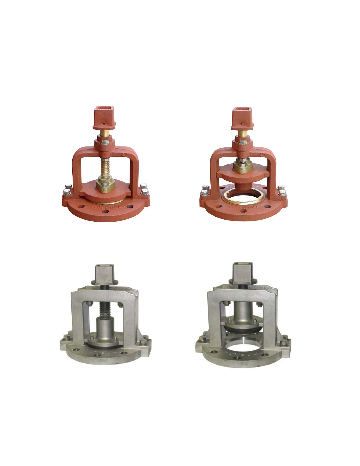
Non-Rising Stem** Rising Stem**
Trumbull Mud Valves are designed primarily
for use in settling tanks of water and wastewater
treatment plants. Their intended use is to
drain tanks for maintenance or cleaning.
They are for low pressure applications only;
consult Trumbull for special requirements.
For applications requiring more corrosion
protection than cast iron, the yoke,
flange, guides and gate of these
Mud Valves are cast from Type 316
stainless steel. The one-piece, Type
316 stem has a permanently bonded
coating to protect against galling for
a lifetime of maintenance-free operation.
Cast components eliminate corrosion problems frequently
caused when stainless steel is welded. Castings are
passivated after machining, per ASTM A-967. Heavy-duty
design incorporates generous wall thicknesses and stem
diameters for maximum strength and corrosion protection.
Seat is SBR rubber for positive shutoff. Mechanically retained
seat is field-replaceable. Fasteners are Type 316 stainless.
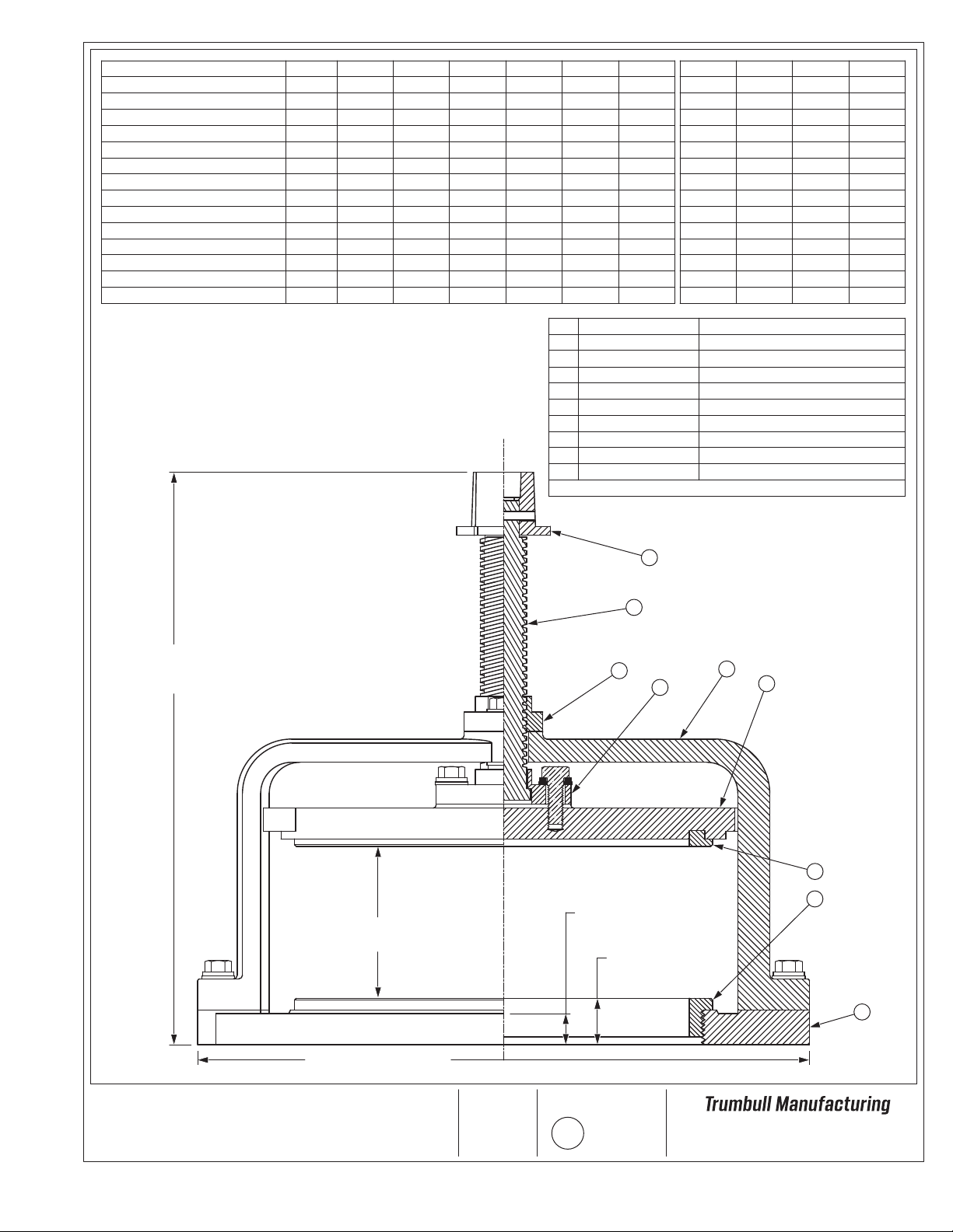
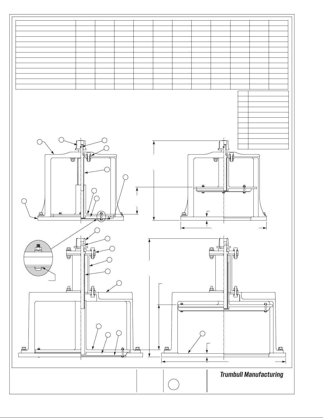
See pages G-32 and G-33 for drawings.
Nuts, bolts and gaskets for mounting to floor pipe are
NOT furnished but can be ordered separately.
Cast 316 Stainless Steel Mud Valves
Heavy-Duty Design – Certified to NSF-61 and NSF-372 in USA and Canada
© 2023 Trumbull Manufacturing
09/01/20 Page Revision Page G-31
Domestic
Non-
Domestic Domestic
Non-
Domestic
* Consult Trumbull for availability.
** For product weights, see drawings on Pages G-32 & G-33.
Page 5of 12