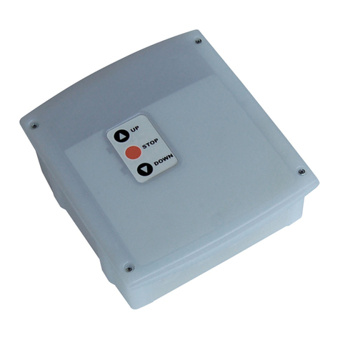
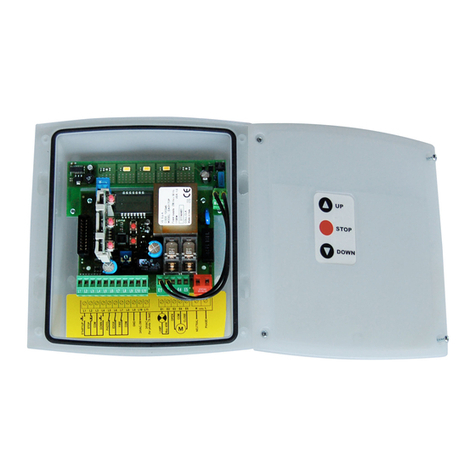
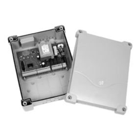
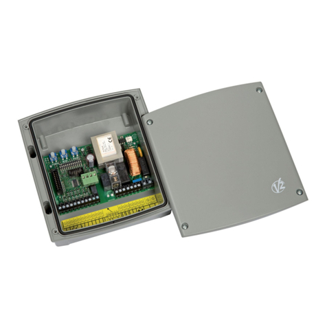
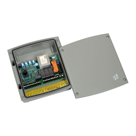
V2 EASY Series User manual

CENTRALE DI COMANDO ANALOGICA PER SERRANDE
AVVOLGIBILI E PORTE BASCULANTI
ANALOG CONTROL UNIT FOR ROLLER SHUTTERS AND
COUNTERWEIGHT BALANCED DOORS
ARMOIRE DE COMMANDE ANALOGIQUE POUR STORES
ET PORTES BASCULANTES
CUADRO DE MANIOBRAS ANALÓGICO PARA TOLDOS Y
PUERTAS BASCULANTES
QUADRO ELÉCTRICO ANALÓGICO PARA ESTORES DE
ENROLAR E TOLDOS
I
GB
F
E
P
IL n. 207-1
EDIZ. 03/03/2008
V2 S.p.A.
Corso Principi di Piemonte, 65/67 - 12035 RACCONIGI (CN) ITALY
tel. +39 01 72 81 24 11 fax +39 01 72 84 050
[email protected] www.v2home.com
Easy (Pr. 1.3)


I
AVVERTENZE IMPORTANTI .......................................................1
CONFORMITÀ ALLE NORMATIVE..............................................1
DESCRIZIONE DELLA CENTRALE ...............................................1
TABELLA COLLEGAMENTI ELETTRICI.........................................2
INGRESSO FIRE.........................................................................3
INSTALLAZIONE DELLA COSTA OTTICA ....................................3
FUNZIONE OROLOGIO..............................................................3
VERSIONI CON PULSANTIERA...................................................3
CARATTERISTIC E TECNIC E...................................................3
LOGIC E DI FUNZIONAMENTO ................................................4
TEMPO DI LAVORO ..................................................................5
TEMPO DI PAUSA.....................................................................5
RITARDO DI SPEGNIMENTO LUCI DI CORTESIA ........................5
FUNZIONAMENTO TRAMITE TELECOMANDO...........................6
MEMORIZZAZIONE DEI TELECOMANDI ....................................6
CANCELLAZIONE TOTALE CODICI MEMORIZZATI
(solo EASY-RI o EASY-CRI) ........................................................6
VISUALIZZAZIONI E SEGNALAZIONI MEDIANTE LED .................7
MONTAGGIO DEI PASSACAVI ..................................................8
GB
IMPORTANT REMARKS.............................................................9
COMPLIANCE WIT LEGISLATION ............................................9
DESCRIPTION OF T E CONTROL UNIT......................................9
ELECTRIC CONNECTIONS TABLE ..............................................10
FIRE INPUT ...............................................................................11
INSTALLATION OF T E OPTICAL SAFETY EDGE.........................11
TIMER FUNCTION.....................................................................11
MODELS WIT PUS -BUTTON PANEL ......................................11
TEC NICAL SPECIFICATIONS....................................................11
OPERATING LOGICS ................................................................12
WORKING TIME .......................................................................13
PAUSE TIME .............................................................................13
DELAY IN TURNING OFF T E COURTESY LIG T........................13
REMOTE CONTROL OPERATING ...............................................14
SAVING T E REMOTE CONTROLS ............................................14
COMPLETE DELETION OF SAVED CODES
(EASY-RI or EASY-CRI only).......................................................14
VISUALISATION AND SIGNALLING USING LED ..........................15
CABLE GLAND ASSEMBLY........................................................16
F
CONSEILS IMPORTANTS ...........................................................17
CONFORMITÉ AUX NORMES....................................................17
DESCRIPTION DE L'ARMOIRE DE COMMANDE.........................17
TABLEAU BRANC EMENTS ELECTRIQUES ................................18
ENTREE « FIRE ».......................................................................19
INSTALLATION DE LA BARRE PALPEUSE ....................................19
FONCTION ORLOGE...............................................................19
MODELES AVEC TABLEAU À POUSSOIRS ................................19
CARACTÉRISTIQUES TEC NIQUES............................................19
LOGIQUES DE FONCTIONNEMENT ...........................................20
TEMPS DE TRAVAIL ..................................................................21
TEMPS DE PAUSE .....................................................................21
RETARD D’EXTINTION LUMIÈRES DE COURTOISIE.....................21
FONCTIONNEMENT PAR TÉLÉCOMMANDE ..............................22
MÉMORISATION DES TÉLÉCOMMANDES .................................22
EFFACEMENT COMPLET DES CODES MÉMORISÉS
(seulement EASY-RI ou EASY-CRI).............................................22
AFFIC AGES ET SIGNALISATIONS AU MOYEN D'UN
VOYANT LUMINEUX (DEL)........................................................23
MONTAGE DES PASSE-CÂBLES.................................................24
E
ADVERTENCIAS IMPORTANTES ................................................25
CONFORMIDAD A LAS NORMATIVAS ......................................25
DESCRIPCION DEL CUADRO ....................................................25
TABLA CONEXIONES ELECTRICAS ............................................26
ENTRADA “FIRE” .....................................................................27
INSTALACION DE LA BANDA DE SEGURIDAD...........................27
FUNCIÓN RELOJ.......................................................................27
VERSION CON BOTONERA .......................................................27
CARACTERISTICAS TÉCNICAS..................................................27
LOGICAS DE FUNCIONAMIENTO..............................................28
TIEMPO DE TRABAJO ...............................................................29
TIEMPO DE PAUSA...................................................................29
TEMPORIZACION DE LA LUZ DE GARAJE .................................29
FUNCIONAMIENTO A TRAVES DEL TRANSMISOR .....................30
MEMORIZACION DE LOS TRANSMISORES................................30
CANCELACION TOTAL DE LOS CODIGOS
MEMORIZADOS (solo EASY-RI o EASY-CRI)...............................30
VISUALIZACIONES Y SEÑALACIONES MEDIANTE LED...............31
MONTAJE DE LOS PRENSAESTOPAS .........................................32
P
AVISOS IMPORTANTES ............................................................33
EM CONFORMIDADE COM AS NORMAS ................................33
DESCRIÇÃO DO QUADRO ELÉCTRICO ....................................33
TABELA DE LIGAÇÕES ELÉCTRICAS..........................................34
ENTRADA “FIRE” ....................................................................35
INSTALAÇÃO DA BANDA DE SEGURANÇA ..............................35
FUNÇÃO RELÓGIO ..................................................................35
MODELOS COM BOTÕES ........................................................35
CARACTERÍSTICAS TÉCNICAS..................................................35
LÓGICAS DE FUNCIONAMENTO ..............................................36
TEMPOS DE OPERAÇÃO ..........................................................37
TEMPO DE PAUSA....................................................................37
ATRASO NO APAGAMENTO DAS LUZES DE CORTESIA ............37
FUNCIONAMENTO POR CONTROLO REMOTO ........................38
LÓGICA DE COMANDO DAS LUZES POR CONTROLO
REMOTO..................................................................................38
CANCELAMENTO TOTAL DOS CÓDIGOS MEMORIZADOS
(apenas EASY-RI ou EASY-CRI)..................................................38
VISUALIZAÇÕES E SINALIZAÇÕES MEDIANTE UM LED ............39
MONTAGEM DOS PASSADORES DE CABOS ............................40


ITALIANO
1
AVVERTENZE IMPORTANTI
Per chiarimenti tecnici o problemi di installazione la
V2 S.p.A. dispone di un servizio di assistenza clienti attivo
durante le ore di ufficio TEL. (+39) 01 72 81 24 11
V2 S.p.A. si riserva il diritto di apportare eventuali
modifiche al prodotto senza preavviso; inoltre declina ogni
responsabilità per danni a persone o cose dovuti ad un uso
improprio o ad un’errata installazione.
Leggere attentamente il seguente manuale di
istruzioni prima di procedere con l'installazione e la
programmazione della centrale di comando.
• Il presente manuale di istruzioni è destinato solamente a
personale tecnico qualificato nel campo delle installazioni di
automazioni.
• Nessuna delle informazioni contenute all'interno del manuale
può essere interessante o utile per l'utilizzatore finale.
• Qualsiasi operazione di manutenzione o di programmazione
deve essere eseguita esclusiavamente da personale qualificato.
L’AUTOMAZIONE DEVE ESSERE REALIZZATA IN
CONFORMITÀ VIGENTI NORMATIVE EUROPEE:
EN 60204-1 (Sicurezza del macchinario, equipaggiamento
elettrico delle macchine, parte 1: regole generali).
EN 12445 (Sicurezza nell'uso di chiusure automatizzate,
metodi di prova).
EN 12453 (Sicurezza nell'uso di chiusure automatizzate,
requisiti).
• L'installatore deve provvedere all'installazione di un
dispositivo (es. interruttore magnetotermico) che assicuri il
sezionamento onnipolare del sistema dalla rete di
alimentazione. La normativa richiede una separazione dei
contatti di almeno 3 mm in ciascun polo (EN 60335-1).
• Una volta effettuati i collegamenti sulla morsettiera, è
necessario mettere delle fascette rispettivamente sui
conduttori a tensione di rete in prossimità della morsettiera e
sui conduttori per i collegamenti delle parti esterne (accessori).
In tal modo, nel caso di un distacco accidentale di un
conduttore, si evita che le parti a tensione di rete possano
andare in contatto con parti a bassissima tensione di sicurezza.
• Per la connessione di tubi rigidi e flessibili o passacavi
utilizzare raccordi conformi al grado di protezione IP55 o
superiore.
• L’installazione richiede competenze in campo elettrico e
meccanico; deve essere eseguita solamente da personale
qualificato in grado di rilasciare la dichiarazione di conformità
di tipo A sull’installazione completa (Direttiva macchine
89/392 CEE, allegato IIA).
• E’ obbligo attenersi alle seguenti norme per chiusure
veicolari automatizzate: EN 12453, EN 12445, EN 12978
ed alle eventuali prescrizioni nazionali.
• Anche l’impianto elettrico a monte dell’automazione deve
rispondere alle vigenti normative ed essere eseguito a
regola d’arte.
• La regolazione della forza di spinta dell’anta deve essere
misurata con apposito strumento e regolata in accordo ai
valori massimi ammessi dalla normativa EN 12453.
• Consigliamo di utilizzare un pulsante di emergenza da
installare nei pressi dell’automazione (collegato all’ingresso
STOP della scheda di comando) in modo che sia possibile
l’arresto immediato del cancello in caso di pericolo.
• Collegare il conduttore di terra dei motori all'impianto di
messa a terra della rete di alimentazione.
CONFORMITÀ ALLE NORMATIVE
V2 S.p.A. dichiara che i prodotti EASY sono conformi ai requisiti
essenziali fissati dalle seguenti direttive:
- 89/336/CEE (Direttiva EMC secondo le norme EN 61000-6-2,
EN 61000-6-3)
- 73/23/CEE (Direttiva Bassa Tensione secondo le norme
EN 60335-1)
- 99/05/CEE (Direttiva Radio secondo le norme EN 301 489-3)
Racconigi, lì 20/04/2006
Il rappresentante legale della V2 S.p.A.
A.Livio Costamagna
DESCRIZIONE DELLA CENTRALE
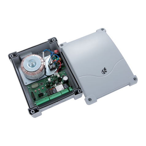
La centrale digitale EASY è un innovativo prodotto V2 che
garantisce sicurezza ed affidabilità per l'automazione di serrande
avvolgibili, porte basculanti e sezionali industriali.
La progettazione della EASY ha mirato alla realizzazione di un
prodotto che si adatta a tutte le esigenze, ottenendo una
centrale estremamente versatile che soddisfa tutti i requisiti
necessari per un'installazione funzionale ed efficiente.
• Uscita 230 VAC per 1 motore monofase
• Uscita 230 VAC per lampeggiante (dotato di scheda
intermittenza) o luce di cortesia temporizzabile
• Ingresso per selettore chiave o pulsante (START)
• Ingressi per comandi separati SALI/SCENDI (UP/DOWN)
• Ingresso per pulsante si sicurezza (STOP)
• Ingresso per fotocellula di sicurezza con test automatico di
funzionamento (P OTO)
• Ingresso per costa sensibile di sicurezza meccanica o
elettronica con test automatico di funzionamento (EDGE)
• Ingresso per emergenza incendio (FIRE)
• Monitoraggio degli ingressi tramite LED
• Logica di funzionamento e tempi di lavoro programmabili
tramite il tasto di programmazione e 8 LED
• Possibilità di funzionamento in modalità UOMO PRESENTE
EASY-RI
• Ricevitore 433,92 M z radio a bordo
• Possibilità di memorizzare 18 trasmettitori Personal Pass
433,92 M z.
• Permette la cancellazione totale dei codici memorizzati
EASY-RM
• Connettore rapido per l’inserimento di un ricevitore della
serie Mr1.
EASY-CRI
• Ingresso per costa ottica con alimentazione in corrente
continua a 24V e regolazione della potenza del trasmettitore
ATTENZIONE: utilizzare solo ed esclusivamente le coste
ottiche FEEL (vedi catalogo V2).
• Ricevitore 433,92 M z radio a bordo
• Possibilità di memorizzare 18 trasmettitori Personal Pass
433,92 M z.
• Permette la cancellazione totale dei codici memorizzati

ITALIANO
2
COLLEGAMENTI ELETTRICI
EASY-RM EASY-RI / EASY-CRI
L1 START/UP. Contatto N.A.
L2 STOP. Contatto N.C.
L3 COMUNE (-)
L4 DOWN. Contatto N.A.
L5 FOTOCELLULA. Contatto N.C.
L6 COSTA. Contatto N.C.
L7 FIRE. Contatto N.C.
L8 COMUNE (-)
L9 COMUNE ACCESSORI
Solo per i modelli EASY-CRI
L9 REGOLAZIONE POTENZA PER COSTA OTTICA
L10 24VAC ACCESSORI (24VDC per i modelli EASY-CRI)
L11 24VAC PER TEST FOTO / COSTA (24VDC per i modelli
EASY-CRI)
E1 - E2
LAMPEGGIANTE 230VAC / 120VAC (dotato di scheda
intermittenza)
LUCE CORTESIA 230VAC / 120VAC
E3 MOTORE APRE
E4 COMUNE 230VAC / 120VAC
E5 MOTORE C IUDE
NNEUTRO 230VAC / 120VAC
LFASE 230VAC / 120VAC
A1 CALZA ANTENNA
A2 ANTENNA POLO CALDO
Solo EASY-CRI
ATTENZIONE: Gli ingressi normalmente chiusi STOP
(L2), FOTOCELLULA (L5), COSTA (L6) , FIRE (L7), se non sono
utilizzati devono essere ponticellati con il COMUNE (-)
ATTENZIONE: un collegamento errato dell’antenna
compromette seriamente il funzionamento RADIO della
centrale.

ITALIANO
3
INGRESSO FIRE
Ingresso di sicurezza per il collegamento di un allarme
antincendio o di altro tipo che richiede l’apertura automatica
immediata della porta. Quando si apre il contatto FIRE la porta
viene aperta e non può essere richiusa fino a quando il contatto
non viene ripristinato.
INSTALLAZIONE DELLA COSTA OTTICA
La centrale EASY-CRI è predisposta per l'installazione di una costa
ottica con alimentazione in corrente continua a 24V e regolazione
della potenza del trasmettitore.
ATTENZIONE: utilizzare solo ed esclusivamente le coste
ottiche FEEL (vedi catalogo V2).
Collegare il trasmettitore e il ricevitore secondo la seguente
tabella.
Dopo aver effettuato i collegamenti, alimentare la centrale e
regolare la potenza con il trimmer presente sulla centrale fino ad
ottenere il funzionamento ottimale della costa.
FUNZIONE OROLOGIO
Nella logica di funzionamento automatica, durante la fase di
pausa il timer di conteggio del tempo di richiusura automatica
viene reinizializzato ogni volta che si chiude il contatto tra il
morsetto di START (L1) e il COMUNE (L3).
Se il contatto rimane chiuso, il conteggio del tempo rimane di
fatto congelato finchè il contatto non viene aperto. È possibile
così collegare il morsetto di start a un timer per programmare gli
orari di apertura e chiusura della porta.
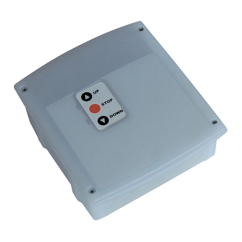
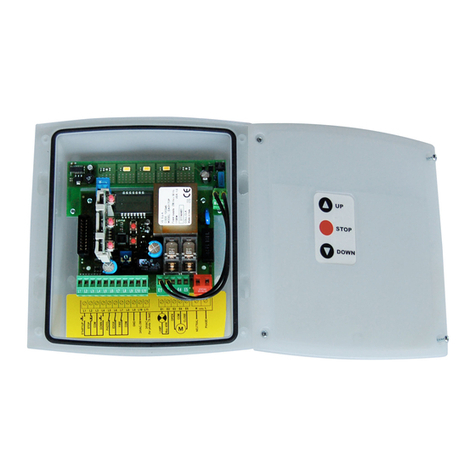
VERSIONI CON PULSANTIERA
La centrale EASY viene prodotta in alcune versioni speciali dotate
di una pulsantiera di comando posta sul coperchio della scatola.
Il modello con la pulsantiera a 3 tasti
permette di comandare la centrale con
logica di funzionamento UP/DOWN.
I pulsanti funzionano in parallelo ai comandi sulla morsettiera.
Questi rimangono tutti attivi compreso il comando di STOP, che
se non utilizzato, deve essere ponticellato con il comune.
Le versioni dotate di pulsantiera consentono inoltre di attivare
l’automazione in modalità UOMO PRESENTE in caso di
malfunzionamento dei dispositivi di sicurezza.
Tenendo premuto il tasto della pulsantiera, dopo 5 secondi viene
attivata l’automazione ignorando i dispositivi di sicurezza; il
motore si ferma immediatamente appena si rilascia il pulsante.
CARATTERISTICHE TECNICHE
TRASMETTITORE RICEVITORE
L6CAVO NERO
L8 CAVO BLU CAVO BLU
L9 CAVO NERO
L10 CAVO MARRONE
L11 CAVO MARRONE
Alimentazione 230VAC - 50/60 z (EASY)
120VAC - 50/60 z (EASY-120V)
Carico max motore 1100W (EASY)
600W (EASY-120V)
Carico max accessori 24V 3W
Temperatura di lavoro -20°C / +60°C
Fusibile di protezione F1 = 5A
Dimensioni 170 x 185 x 70 mm
Peso 800g
Protezione IP55

ITALIANO
4
LED (DIP) LED SPENTO (DIP OFF) LED ACCESO (ON)
1. start / up LOGICA START/STOP: Il morsetto Start comanda sia
l'apertura che la chiusura. Il morsetto Down è disabilitato.
LOGICA UP/DOWN: Il morsetto Start comanda sempre
l'apertura; il morsetto Down comanda sempre la chiusura.
2. open / stop START NON ATTIVO IN APERTURA: Il comando viene
ignorato.
START ATTIVO IN APERTURA: Interrompe l'apertura (non
viene caricato l'eventuale timer per la richiusura)
3. auto / down LOGICA PASSO-PASSO: La chiusura viene comandata con
lo start (o il down).
LOGICA AUTOMATICA: La chiusura inizia
automaticamente dopo il tempo di pausa impostato.
4. photo FOTOCELLULA NON ATTIVA IN APERTURA: L'interruzione
del fascio viene ignorata.
FOTOCELLULA ATTIVA IN APERTURA: Il motore si ferma
fino al disimpegno.
5. edge TEST COSTA NON ATTIVO: Non viene eseguito il test della
costa
TEST COSTA ATTIVO CON RICONOSCIMENTO TIPO DI
COSTA: Viene eseguito il test della costa
6. dm / fire LOGICA A IMPULSI: Le fasi di apertura e chiusura durano il
tempo di lavoro impostato.
LOGICA UOMO PRESENTE: Le fasi di apertura e chiusura
durano fintanto che il comando è presente sul relativo
morsetto.
7. light / canc
LAMPEGGIANTE: L'uscita (E1 - E2) viene attivata a
intermittenza (2 z) durante le fasi di apertura e chiusura
e durante la pausa se è attiva la richiusura automatica.
LUCE DI CORTESIA: L'uscita (E1 - E2) viene attivata fissa
durante le fasi di apertura, pausa e chiusura. Tornando a
riposo viene attivato un timer per la durata impostata.
8. motor / test
/ error
TEST FOTOCELLULA NON ATTIVO: Non viene eseguito il
test della fotocellula
TEST FOTOCELLULA ATTIVO: Viene eseguito il test della
fotocellula
= Led spento
= Led acceso
LOGICHE DI FUNZIONAMENTO
Gli otto led presenti sulla scheda oltre a visualizzare lo stato degli
ingessi e del ciclo di funzionamento, permettono la
programmazione delle varie funzioni per personalizzare il
funzionamento della centrale. Ogni LED corrisponde ad una
determinata funzione ed il suo stato (acceso/spento) equivale alla
posizione ON/OFF dei vecchi sistemi a dip-switch.
Per visualizzare le impostazioni correnti è sufficiente premere il
tasto MENU fino a quando i LED si accendono visualizzando le
impostazioni correnti per 12s.
(Configurazione di default)
Per modificare le logiche di funzionamento procedere come segue:
NOTA: la modifica dei parametri avviene tramite la pressione del
tasto MENU. Una pressione di durata compresa tra 1 e 5 secondi
verrà indicata con TL mentre una pressione breve di durata
inferiore ad 1 secondo verrà indicata con TS.
1. Premere il tasto MENU per un tempo (TL)
2. I led visualizzano l'impostazione corrente dei dip switch
virtuali per 12s
3. Entro i 12s premere nuovamente MENU per un tempo (TS)
4. Il led start/up si accende: è a luce fissa se il parametro
associato è abilitato, a luce lampeggiante se il parametro è
disabilitato.
5. Premere MENU per un tempo (TL) per modificare lo stato del
led selezionato
6. Premere MENU per un tempo (TS) per selezionare il led
successivo
7. Modificare le impostazioni secondo le proprie esigenze e
attendere 5s dall'ultima pressione
8. I LED visualizzano le nuove impostazioni per 12s, i nuovi dati
vengono salvati in memoria e la centrale esce dalla modalità
programmazione
9. Per una eventuale verifica premere MENU per visualizzare le
nuove impostazioni
LOGICA PASSO-PASSO: il comando di start inizia un ciclo
APRE-STOP-C IUDE-STOP-APRE....
LOGICA AUTOMATICA: il comando di start inizia un ciclo
APRE-PAUSA-C IUDE-STOP
LOGICA START/STOP: l'ingresso START/UP comanda il ciclo di
funzionamento PASSO-PASSO o AUTOMATICO in base alla logica
di funzionamento programmata. L'ingresso DOWN non è attivo
LOGICA UP/DOWN: l'ingresso START/UP comanda sempre
l'apertura e l'ingresso DOWN comanda sempre la chiusura,
indipendentemente dalla logica di funzionamento programmata.
UP + DOWN premuti contemporaneamente equivalgono ad un
comando di STOP.
LOGICA UOMO PRESENTE: l'utilizzatore deve tenere premuto il
pulsante di start per tutta la durata dell'apertura o della chiusura
che si desidera effettuare.
Se il tasto collegato all'ingresso di START si danneggia rimanendo
sempre chiuso, il motore si fermerà dopo il tempo di lavoro
impostato. La logica uomo presente è utilizzabile sia con logica
START/STOP che UP/DOWN.
Il comando di STOP interrompe il ciclo di funzionamento,
indipendentemente dallo stato degli ingressi di comando. Quindi
se il tasto UP o DOWN è premuto, l'intervento dello STOP ferma il
moto e al suo rilascio il motore NON SI MUOVE FINO A QUANDO
L'INGRESSO UP o DOWN NON VIENE RILASCIATO E
NUOVAMENTE PREMUTO.

ITALIANO
5
TEST FOTOCELLULA E COSTA: il test delle fotocellule verifica il
corretto funzionamento della fotocellula ogni volta che la centrale
riceve un comando di apertura o chiusura. Se il test fallisce il led
photo lampeggia a 2 z per 5 secondi, insieme al led
motor/test/error.
Il TEST COSTA, utilizzabile con coste sensibili di tipo elettronico,
esegue la stessa verifica sulle coste sensibili. Se il test fallisce il led
EDGE lampeggia insieme al led motor/test/error
Durante il TEST la centrale riconosce anche se la costa fornisce un
contatto normalmene chiuso o un’impedenza (coste a gomma
conduttiva).
ATTENZIONE: se si utilizza una costa a gomma conduttiva è
obbligatorio attivare il TEST COSTA (DIP 5), perchè
altrimenti la costa non viene riconosciuta.
La segnalazione di ERRORE TEST si ripete dopo ogni comando per
un tempo di 5s.
TEMPO DI LAVORO
Per modificare il tempo di lavoro procedere come segue:
NOTA: la modifica dei parametri avviene tramite la pressione del
tasto MENU. Quando è richiesto di premere per un tempo (TS)
bisogna premere e subito rilasciare.
Quando è richiesto di premere per un tempo (TL) bisogna tenere
premuto il tasto (circa 2 secondi) finchè i led non cambiano
indicando che il comando è stato eseguito.
1. Premere il tasto MENU per un tempo (TL).
2. I led visualizzano l'impostazione corrente dei dip switch
virtuali per 12s.
3. Entro i 12s premere nuovamente MENU per un tempo (TL).
4. I led visualizzano per 12s il tempo di lavoro impostato.
5. Entro i 12s premere il tasto MENU per un tempo (TS), ad
ogni pressione i led successivi si accendono uno alla volta,
quando sono tutti accesi ricomincia da 1 led. La tabella
riporta l'impostazione del tempo di lavoro in base al numero
di led accesi.
6. Quando l'impostazione è corretta attendere 12s: i nuovi dati
vengono salvati in memoria e la centrale esce dalla modalità
programmazione.
TEMPO DI PAUSA
Per modificare il tempo di pausa procedere come segue:
NOTA: la modifica dei parametri avviene tramite la pressione del
tasto MENU. Quando è richiesto di premere per un tempo (TS)
bisogna premere e subito rilasciare.
Quando è richiesto di premere per un tempo (TL) bisogna tenere
premuto il tasto (circa 2 secondi) finchè i led non cambiano
indicando che il comando è stato eseguito.
1. Premere il tasto MENU per un tempo (TL).
2. I led visualizzano l'impostazione corrente dei dip switch
virtuali per 12s.
3. Entro i 12s premere nuovamente MENU per un tempo (TL).
4. I led visualizzano per 12s il tempo di lavoro impostato.
5. Entro i 12s premere nuovamente il tasto MENU per un
tempo (TL).
6. I led visualizzano per 12s il tempo di pausa impostato.
7. Entro i 12s premere il tasto MENU per un tempo (TS), ad
ogni pressione i led successivi si accendono uno alla volta,
quando sono tutti accesi ricomincia da 1 led. La tabella
riporta l'impostazione del tempo di pausa in base al numero
di led accesi.
8. Quando l'impostazione è corretta attendere 12s: i nuovi dati
vengono salvati in memoria e la centrale esce dalla modalità
programmazione
RITARDO DI SPEGNIMENTO LUCI DI
CORTESIA
Quando la centrale torna a riposo dopo un ciclo di
funzionamento, la luce di cortesia rimane accesa per un tempo
impostabile fino a 5 minuti. L'impostazione del ritardo di
spegnimento può essere eseguita solo se l'uscita è settata come
luce di cortesia (dip switch virtuale light/canc ON).
Per modificare il ritardo di spegnimento della luce di cortesia,
procedere come segue:
1. Premere e tenere premuto il tasto MENU, ignorando la
visualizzazione dei dip switch virtuali sui led
2. Dopo 5s i led si spengono e la luce di cortesia si accende
3. Continuare a tenere premuto il tasto MENU per il tempo
che si desidera impostare
4. Rilasciare il testo MENU. La luce di cortesia si spegne e il
tempo per il quale è rimasta accesa viene memorizzato
come ritardo di spegnimento.
LED TEMPO LED TEMPO
1 10 sec. 5 45 sec.
2 15 sec. 6 60 sec.
3 20 sec. 7 90 sec.
4 30 sec. 8 120 sec.
= Led spento
= Led acceso
= Led spento
= Led acceso
LED TEMPO LED TEMPO
1 15 sec. 5 60 sec.
2 20 sec. 6 90 sec.
3 30 sec. 7 120 sec.
4 45 sec. 8 180 sec.

ITALIANO
6
MEMORIZZAZIONE DEI TELECOMANDI
Se state utilizzando una centrale modello EASY-RM per
memorizzare i telecomandi leggete attentamente le istruzioni
allegate al ricevitore MR1.
Se state utilizzando una centrale modello EASY-RI oEASY-CRI
per memorizzare i telecomandi procedete come segue:
1. Premere il tasto MENU per un tempo breve (TS)
2. La centrale attiva la fase di apprendimento radio e rimane in
attesa di una trasmissione valida (entro 5s) visualizzando un
led acceso che si sposta velocemente nella direzione indicata
3. Trasmettere con il telecomando che si desidera memorizzare
4. I led visualizzano la memorizzazione avvenuta accendendo
per 2s tutti i led
5. Per 5s la centrale torna in attesa di una trasmissione valida
visualizzando nuovamente un led acceso che si sposta
velocemente nella direzione indicata nel disegno sopra.
6. Trasmettere con un altro telecomando da memorizzare o
attendere che il led si spenga.
NOTA: per aggiungere codici in memoria è anche possibile
attivare la modalità di apprendimento radio usando un
telecomando già memorizzato.
Indipendentemente dal tasto o dalla combinazione di tasti
memorizzata, per attivare la modalità di apprendimento radio
bisogna tenere premuta la combinazione tasto 1 + tasto 2 oppure
tasto 1 + tasto 3 per cinque secondi. In questo caso l'attesa di
tramissione valida viene segnalata, oltre che dalla rotazione del
led, anche dall'accensione del lampeggiante (o luce di cortesia) a
luce fissa. La memorizzazione di un codice viene segnalata
mediante un breve spegnimento della luce.
ATTENZIONE: quando la memoria è completa e quindi non è più
possibile memorizzare altri telecomandi, se si tenta di attivare la
fase di apprendimento radio, la centrale risponde facendo
lampeggiare tutti i led per 2 s.
CANCELLAZIONE TOTALE CODICI
MEMORIZZATI (solo EASY-RI o EASY-CRI)
Per cancellare tutti i codici presenti in memoria procedere come
segue:
1. Rimuovere l'alimentazione alla centrale
2. Tenendo premuto il tasto MENU ripristinare la tensione di
alimentazione
3. Per tutta la durata della pressione del tasto il led light/canc
lampeggia.
4. Al rilascio del tasto i led si spengono per 2 s, quindi
emettono la segnalazione di POWER ON (8 led accesi fissi
per 2s) e la centrale passa la funzionamento normale.
ATTENZIONE: Se il tasto non viene rilasciato entro 5 secondi
anche il led motor/test/error comincia a lampeggiare e la
centrale va in blocco. Per sbloccarla occorre togliere e ridare
alimentazione.
FUNZIONAMENTO TRAMITE TELECOMANDO
Modello EASY-RM
La centrale è predisposta per l'innesto di un ricevitore della serie
MR1 con architettura super-eterodina ad elevata sensibilità.
ATTENZIONE: Prima di innestare il ricevitore disalimentare
la centrale di comando. Porre la massima attenzione al verso di
innesto del ricevitore (vedi paragrafo COLLEGAMENTI ELETTRICI).
Il modulo ricevitore MR1 ha a disposizione 4 canali ad ognuno dei
quali è associato un comando della centrale:
• CANALE 1 쩚쩚쩛쩛UP o START
• CANALE 2 쩚
쩚쩛
쩛STOP
• CANALE 3 쩚쩚쩛쩛DOWN
• CANALE 4 쩚쩚쩛쩛LUCI DI CORTESIA
ATTENZIONE: Per la programmazione dei 4 canali e delle
logiche di funzionamento leggere attentamente le istruzioni
allegate al ricevitore MR1.
Modelli EASY-RI e EASY-CRI
Il funzionamento dei telecomandi dipende dalla logica di
funzionamento impostata con il dip switch virtuale 1.
Logica START/STOP: solo il tasto o la combinazione di tasti
memorizzata attiva la centrale (è possibile memorizzare più di una
combinazione per lo stesso telecomando), e il comando
corrisponde allo start.
Logica UP/DOWN:
ad ogni tasto del
telecomando viene
associata una funzione.
E' sufficiente memorizzare
un tasto qualsiasi del
telecomando.
LOGICA DI COMANDO DELLE LUCI TRAMITE
TELECOMANDO
ATTENZIONE: questa funzione è abilitata solo se il DIP 7 è
impostato su ON.
La luce di cortesia è comandabile tramite il tasto 4 del
telecomando (nei modelli EASY-RI e EASY-CRI se è impostata la
logica UP/DOWN); oppure, nel modello EASY-RM, con un tasto
qualunque del telecomando memorizzato sul canale 4 del
ricevitore MR1.
La logica di azionamento è bistabile: se la luce di cortesia è
spenta la si accende e viceversa. La luce si spegne in ogni caso
dopo 10 minuti.
ATTENZIONE:
• Se dopo aver acceso la luce inizia un ciclo di apertura, al
termine di questo viene attivato il timer e allo scadere la
luce viene spenta.
• Non è possibile spegnere la luce di cortesia mentre la
serranda è in movimento (apertura o chiusura).
UP
DOWN
STOP
LUCE
= Led spento
= Led acceso

ITALIANO
7
VISUALIZZAZIONI E SEGNALAZIONI MEDIANTE LED
Sulla scheda è montata una fila di 8 led rossi, tramite i quali vengono
gestite tutte le segnalazioni utili per l'installatore e l'utente.
Durante il funzionamento normale della centrale (NON durante la fase di
programmazione), il significato di ciascun led può essere ricavato dalla
seguente tabella:
*Ciclo di funzionamento: il led 7 (light / canc) si accende
secondo la sequente logica:
• Led spento: centrale a riposo
• Led lampeggiante a 2 z: fase di apertura
• Led fisso: centrale a riposo con serranda aperta (se è
attivo il timer per chiusura automatica il led si spegne
brevemente ogni mezzo secondo)
• Led lampeggiante a 4 z: fase di chiusura
LED SPENTO ACCESSO
Led LAMPEGGIANTE (in combinazione con il led 8)
Led 8 spento o acceso Led 8 lampeggiante
1. start / up Sul morsetto start / up
il contatto è aperto
Sul morsetto start / up
il contatto è chiuso
Comando di start tramite
telecomando
Fallita scrittura in flash a fine
programmazione
2. open / stop Sul morsetto open / stop
il contatto è aperto
Sul morsetto open / stop
il contatto è chiuso
Comando di stop tramite
telecomando oppure start
abortito causa stop attivo
-
3. auto / down Sul morsetto down
il contatto è aperto
Sul morsetto down
il contatto è chiuso
Comando di down tramite
telecomando -
4. photo Sul morsetto photo
il contatto è aperto
Sul morsetto photo
il contatto è chiuso
Start abortito causa
fotocellulla interrotta Fallito test della fotocellula
5. edge Sul morsetto edge
il contatto è aperto
Sul morsetto edge
il contatto è chiuso
Start abortito causa costa
schiacciata Fallito test della costa
6. dm / fire Sul morsetto fire
il contatto è aperto
Sul morsetto fire
il contatto è chiuso
Start abortito causa allarme
incendio attivo -
7. light / canc - -
Comando luci via
telecomando o cilco di
funzionamento* o
cancellazione codici
Cancellazione codici fallita
8. motor / test
/ error L’uscita motore non è attiva L’uscita motore è attiva Indicazione di errore

ITALIANO
8
MONTAGGIO DEI PASSACAVI
Il contenitore è predisposto per il montaggio di 4 passacavi nelle
apposite sedi con prerottura.
Il tipo di passacavi è indicato in figura.
ATTENZIONE:
• Prima di forare il contenitore smontare la scheda elettronica.
• Forare il contenitore con una fresa adeguata rispetto alle
dimensioni del passacavo.
• Fissare i passacavi con gli apposidi dadi.

ENGLISH
9
IMPORTANT REMAR S
For any installation problems please contact
V2 S.p.A. TEL. (+39) 01 72 81 24 11
V2 S.p.A. has the right to modify the product without
previous notice; it also declines any responsibility for
damage or injury to people or things caused by improper
use or wrong installation.
Please read this handbook very carefully before
installing and programming your City4 control unit.
•This handbook is only for qualified technicians, specialized
in installations and automations.
• The content of this handbook does not concern the
end user.
•Every programming and/or every maintenance service
should be done only by qualified technicians.
AUTOMATION MUST BE IMPLEMENTED IN COMPLIANCE
WITH THE EUROPEAN REGULATIONS IN FORCE:
EN 60204-1 (Machinery safety. electrical equipment of
machines, part 1: general rules)
EN 12445 (Safe use of automated locking devices,
test methods)
EN 12453 (Safe use of automated locking devices,
requirements)
• The installer must provide for a device (es. magnetotermical
switch) ensuring the omnipolar sectioning of the equipment
from the power supply.
The standards require a separation of the contacts
of at least 3 mm in each pole (EN 60335-1).
• After making connections on the terminal board, use one
hose clamp to fix dangerous voltage wires near the terminal
board and another hose clamp to fix safety low voltage wires
used for accessories connection; this way, in case of
accidental detachment of a conducting wire, dangerous
voltage parts will not come into contact with safety low
voltage ones.
• The plastic case has an IP55 insulation; to connect flexible
or rigid pipes, use pipefittings having the same insulation
level.
• Installation requires mechanical and electrical skills,
therefore it shall be carried out by qualified personnel only,
who can issue the Compliance Certificate concerning the
whole installation (EEC Machine Directive 89/392, Annex IIA).
• The automated vehicular gates shall comply with the
following rules: EN 12453, EN 12445, EN 12978 as well
as any local rule in force.
• Also the automation upstream electric system shall comply
with the laws and rules in force and be carried out
workmanlike.
• The door thrust force adjustment shall be measured
by means of a proper tool and adjusted according to
the max. limits, alowed by EN 12453.
• We recommend use an emergency button, to be installed by
the automation (connected to the control unit STOP input)
so that the gate may be immediately stopped in case of
danger.
• Always remember to connect the earth according to
current standards (EN 60335-1, EN 60204-1).
COMPLIANCE WITH LEGISLATION
V2 S.p.A. confirms that EASY comply with the basic
requirements in the following directives:
- 89/336/CEE (EMC Directive according to EN 61000-6-2,
EN 61000-6-3 standards)
- 73/23/CEE (Low Voltage Directive according to EN 60335-1
standards)
- 99/05/CEE (Radio Directive according to EN 301,489-3
standards)
Racconigi, lì 20/04/2006
V2 S.p.A. legal representative
A.Livio Costamagna
DESCRIPTION OF THE CONTROL UNIT
The EASY digital control unit is an innovative V2 product that
guarantees safety and reliability for the automation of winding
shutters, overhead doors and industrial sectionals.
The EASY design focused on creating a product meeting all
requirements, obtaining an extremely versatile control unit,
satisfy all the needs of a practical, efficient installation.
• 230 VAC output for 1 single-phase motor
• 230 VAC output for flashing light or timed courtesy light
• Input for key switch or pushbutton (START)
• Input for separate UP/DOWN commands
• Input for safety pushbutton (STOP)
• Input for safety photocell with automatic operating test
(P OTO)
• Input for safety edge (mechanic or electronic) with
automatic operating test (EDGE)
• Input for fire emergency (FIRE)
• Monitoring the inputs using LED
• Operating logic and working times that can be
programmed using the programming key and 8 LEDs
• Possibility of operating in DEAD MAN mode
EASY-RI
• Fitted 433.92 M z radio receiver
• Possibility of saving 18 433.92 M z Personal Pass
transmitters.
• Allows the total deletion of stored codes
EASY-RM
• Fast connector to insert a Mr1 series receiver.
EASY-CRI
• Input for optical safety edge with 24V direct current power
supply and adjustment of the power of the transmitter.
WARNING: use only FEEL optical safety edges (see
V2 catalogue)
• Fitted 433.92 M z radio receiver
• Possibility of saving 18 433.92 M z Personal Pass
transmitters.
• Allows the total deletion of stored codes

ENGLISH
10
ELECTRIC CONNECTIONS TABLE
L1 START/UP. N.O. contact
L2 STOP. N.C. contact
L3 COMMON (-)
L4 DOWN. N.O. contact
L5 P OTOCELL. N.C. contact
L6 EDGE. N.C. contact
L7 FIRE. N.C. contact
L8 COMMON (-)
L9 COMMON ACCESSORIES
EASY-CRI only
L9 Adjustment of the power for OPTICAL SAFETY EDGE
L10 24VAC ACCESSORIES (24VDC for EASY-CRI models)
L11 24VAC FOR P OTO / EDGE TEST (24VDC for EASY-CRI
models)
E1 - E2 BLINKER with built-in intermittence (230VAC / 120VAC)
COURTESY LIG T (230VAC / 120VAC)
E3 MOTOR OPENS
E4 COMMON 230VAC / 120VAC
E5 MOTOR CLOSES
NNEUTRAL 230VAC / 120VAC
LP ASE 230VAC / 120VAC
A1 ANTENNA S IELD
A2 ANTENNA
ATTENZIONE: Normally closed inputs STOP (L2),
PHOTOCELL (L5), EDGE (L6), FIRE (L7), if not used must be
bridged through the COMMON terminal (-)
WARNING: a wrong connection of the antenna
compromises seriously the RADIO working of the control
unit.
EASY-RM EASY-RI / EASY-CRI
EASY-CRI only

ENGLISH
11
FIRE INPUT
Safety input for the connection of a fire alarm or another type of
alarm requiring the immediate automatic opening of the door.
When the contact FIRE opens, the doors opens and it is not
possible to close it until the contact is restored.
INSTALLATION OF THE OPTICAL SAFETY
EDGE
The control unit EASY-CRI is preset for the installation of an
optical safety edge with 24V direct current power supply and
adjustment of the power of the transmitter.
WARNING: use only FEEL optical safety edges (see V2
catalogue)
Connect the transmitter and the receiver in accordance with the
following the chart:
After having made all the connections, supply power to the
control unit and adjust the power by means of the trimmer on
the control unit until reached the optimal working of the safety
edge.
CLOC FUNCTION
During the automatic operating logic, when the control unit is in
pause phase each time that the contact between the START ter-
minal (L1) and the COMMON (L3) closes, the timer of the auto-
matic re-closure is restarted.
If the contact keeps closed, the timer is stopped until the contact
opens again. It is possible to connect the start terminal to a timer
in order to programme the opening and closing hours of the door.
MODELS WITH PUSH-BUTTON PANEL
The control unit EASY is produced in special models equipped
with a push-button panel on the top of the box.
The model with a 3-button push-button
panel controls the control unit with
function logic UP/DOWN.
The buttons work in parallel to the controls on the terminal
board. These are all on, included the STOP one, that, if not used,
has to be connected by a jumper with the common.
The models with push-button panel allow to activate the
automation in DEAD MAN mode in case of malfunctioning of the
safety devices.
Keeping pressed the button of the push-button panel, after 5
seconds the automation is activated ignoring the safety devices;
the motor stops immediately as soon as the button is released.
TRANSMITTER RECEIVER
L6 BLACK CABLE
L8 BLUE CABLE BLUE CABLE
L9 BLACK CABLE
L10 BROWN CABLE
L11 BROWN CABLE
Power supply 230VAC - 50/60 z (EASY)
120VAC - 50/60 z (EASY-120V)
Max motors load 1100W (EASY)
600W (EASY-120V)
Max accessories load 24V 3W
Working temperature -20°C / +60°C
Protection fuse F1 = 5A
Dimensions 170 x 185 x 70 mm
Weight 800g
Protection IP55
TECHNICAL SPECIFICATIONS

ENGLISH
12
LED (DIP) LED OFF (DIP OFF) LED ON (ON)
1. start / up START/STOP LOGIC: the Start terminal controls both the
opening and closing. The Down terminal is disabled.
UP/DOWN LOGIC: the Start terminal always controls the
opening; the Down terminal always controls closing.
2. open / stop START IS NOT ON AT T E OPENING: the control is ignored. START IS NOT ON AT T E OPENING: it interrupts the
opening (the possible timer for re-closing is not loaded)
3. auto / down STEP BY STEP LOGIC: closing is controlled with the start
(or down).
AUTOMATIC LOGIC: the closing starts automatically after
the set pause time.
4. photo T E P OTOCELL IS NOT ON AT T E OPENING: the
interruption of the strip is ignored.
T E P OTOCELL IS ON AT T E OPENING: the motor stops
at the end of the release.
5. edge EDGE TEST NOT ON: the edge test is not carried out SAFETY EDGE TEST ON WIT IDENTIFICATION OF SAFETY
EDGE TYPE: the edge test is carried out
6. dm / fire IMPULSE LOGICS: the opening and closing phases during
the set working time
DEAD MAN LOGIC: the opening and closing phases last
for as long as there is a control on the relative terminal.
7. light / canc
FLAS ING LIG T: the output (E1 - E2) is intermittently
activated (2 z) during the opening and closing phases and
during the pause if the automatic re-closing is on.
COURTESY LIG T: output (E1 - E2) is permanently on
during the opening, pause and closure stages. Going back
to rest, a timer is activated for the set time.
8. motor / test
/ error
P OTOCELL TEST NOT ON: the photocell test is not carried
out P OTOCELL TEST ON: the photocell test is carried out
= Led OFF
= Led ON
OPERATING LOGICS
The eight leds on the card not only view the state of inputs and
the operating cycle, but allow for the programming of the various
functions to personalise the control unit. Every LED corresponds
to a specific function and its status (on/off) equates to the
ON/OFF position on the old dip-switch systems.
In order to view the current settings, just press the MENU key
until the LEDS come on, showing the current settings for 12 secs.
(Default setting)
In order to change the functioning logics, proceed as follows:
NOTE: the parameters change by pressing the MENU key.
Keeping the key pressed for a period of between 1 and 5
seconds will be indicated with TL, while a brief pressure of less
than 1 second will be indicated with TS.
1. Press the MENU key for a time (TL)
2. The leds show the current setting of the virtual dip switches
for 12 secs.
3. Within 12 secs. press the MENU key again for a time (TS)
4. The start/up led comes on: it is a permanent light if the
associate parameter is active, and a flashing light if
the parameter is deactivated.
5. Press MENU for a time (TL) to change the status of the
selected led
6. Press MENU for a time (TS) to select the next led
7. Change the settings according to their needs and wait 5
secs. from the last time you pressed.
8. The LEDs show the new settings for 12 secs., the new data
is saved and control unit exits the programming mode
9. In order to make any checks, press MENU to view the new
settings
STEP BY STEP LOGIC: the start command sets off a cycle
OPEN-STOP-CLOSE-STOP-OPEN…
AUTOMATIC LOGIC: the start command sets off a cycle
OPEN-PAUSE-CLOSE-STOP
START/STOP LOGIC: the START/UP input controls the STEP BY
STEP or AUTOMATIC operating cycle according to the
programmed operating logic. DOWN input is not on
UP/DOWN LOGIC: START/UP input always controls the opening
and DOWN input always controls closure, irrespective of the
programmed operating logic.
UP + DOWN pressed simultaneously equates to a STOP
command.
DEAD MAN LOGIC: the user must keep the start key pressed for
the entire opening or closure time desired.
If the key connected to the START input is damaged and stays
permanently closed, the motor will stop after the set working
time.
The logic of DEAD MAN is used both with Start/Stop and
Up/Down logic.
The STOP command interrupts the operating cycle, irrespective of
the status of the command inputs. So, if the UP or DOWN key is
pressed, the intervention of the STOP key, stops the motor and
on its release the motor REMAINS STILL UNTIL T E UP or DOWN
INPUT IS RELEASED AND PRESSED AGAIN.

ENGLISH
13
PHOTOCELL AND EDGE TEST: the test checks that the photocell
is working properly each time the control unit receives a
command to open or close. If the test fails, the photo led flashes
at 2 z for 5 seconds, together with the motor/test/error led.
The EDGE TEST, that can be used with electronic sensitive edges,
carries out the same check on the sensitive edges. If the test
fails, the EDGE led flashes together with the motor/test/error
led.
During the TEST the control unit recognizes also if the safety
edge gives a normally closed contact or an impedance
(conductive rubber edges).
WARNING: if using a conductive rubber safety edge it is
compulsory to activate the TEST of the safety edge (DIP 5),
otherwise the safety edge is not recognized.
The ERROR TEST signal repeats itself after each control, for a
period of 5 secs.
WOR ING TIME
In order to change the working time, proceed as follows:
NOTE: the parameters change by pressing the MENU key. When
it is required to press for a time (TS), it is necessary to press and
immediately release. When required to press for a time (TL), it is
necessary to keep pressed the key (for about 2 seconds) until the
leds change indicating that the control has been made.
1. Press the MENU key for a time (TL).
2. The leds show the current setting of the virtual dip switches
for 12 secs.
3. Within 12 secs. press the MENU key again for a time (TL)
4. The leds show the set working time for 12 secs.
5. Within 12 secs., press the MENU key for a time (TS); each
time it is pressed, the next leds come on one by one. When
they are all on, start again from led 1. The table shows the
working time setting according to the number of leds on.
6. When the setting is correct, wait 12 secs., the new data is
saved and the control unit exits the programming mode.
PAUSE TIME
In order to change the pause time, proceed as follows:
NOTE: the parameters change by pressing the MENU key. When
it is required to press for a time (TS), it is necessary to press and
immediately release. When required to press for a time (TL), it is
necessary to keep pressed the key (for about 2 seconds) until the
leds change indicating that the control has been made.
1. Press the MENU key for a time (TL)
2. The leds show the current setting of the virtual dip switches
for 12 secs.
3. Within 12 secs. press the MENU key again for a time (TL)
4. The leds show the set working time for 12 secs.
5. Within 12 secs. press the MENU key again for a time (TL).
6. The leds show the set pause time for 12 secs.
7. Within 12 secs., press the MENU key for a time (TS); each
time it is pressed, the next leds on one by one.
When they are all on, start again from led 1. The table
shows the pause time setting according to the number of
leds on.
8. When the setting is correct, wait 12 secs., the new data are
saved and the control unit exits the programming mode.
DELAY IN TURNING OFF THE COURTESY
LIGHT
When the control unit returns to standby after an operating
cycle, the courtesy light stays on for a time that can be set for a
period up to 5 minutes. Setting the turn off delay can be done if
output is set as a courtesy light (virtual dip switch light/canc
ON).
In order to change the delay in turning off the courtesy light,
proceed as follows:
1. Press the MENU key and keep it pressed, ignoring the
appearance of the virtual dip switches on the leds.
2. After 5 secs., the leds turn off and the courtesy
light turns on
3. Keep the MENU key pressed for the time required for setting
4. Release the MENU key. The courtesy light turns itself off
and the time it stayed on for is saved as a delay in turning
off.
LED TIME LED TIME
1 10 sec. 5 45 sec.
2 15 sec. 6 60 sec.
3 20 sec. 7 90 sec.
4 30 sec. 8 120 sec.
= Led OFF
= Led ON
= Led OFF
= Led ON
LED TIME LED TIME
1 15 sec. 5 60 sec.
2 20 sec. 6 90 sec.
3 30 sec. 7 120 sec.
4 45 sec. 8 180 sec.

ENGLISH
14
SAVING THE REMOTE CONTROLS
If you are using an EASY-RM control unit model to save the
remote controls, read carefully the instructions attached to the
MR1 receiver.
If you are using an EASY-RI or EASY-CRI control unit model to
save the remote controls, proceed as follows:
1. Press the MENU key for a short time (TS)
2. The control unit activates the radio learning stage and awaits
a valid transmission (within 5 secs.) showing a led on, that
rapidly moving in the direction indicated.
3. Transmit by the remote control you need to store.
4. The leds show saving is complete by turning on all the leds
for 2 secs.
5. For 5 secs., the control unit returns to waiting for a valid
transmission by once again showing a led on, moving
rapidly in the direction shown in the drawing above.
6. Transmit with another remote control to be stored or wait
for the leds to turn off.
NOTE: to add codes in the memory it is also possible to activate
the radio learning mode using an already stored transmitter.
Irrespective of the key or combination of saved keys, to activate
the radio learning mode, keep key 1 + key 2 or key 1 + key 3
pressed, for 5 seconds. In this case, the wait for valid
transmission is signalled not only by the led rotation but also by a
flashing light (or courtesy light) switching on to permanent light.
The saving of a code is indicated with the light briefly turning off.
WARNING: when the memory is full and there is no more space
to save other remote controls, if one tries to activate the radio
learning stage, the control unit replies by flashing all the leds for
2 secs.
COMPLETE DELETION OF SAVED CODES
(EASY-RI or EASY-CRI only)
To delete all the codes in the memory, proceed as follows:
1. Disconnect the power to the control unit
2. By keeping the MENU key pressed, reset the power voltage
3. All the time one is pressing on the key, the light/canc led is
flashing.
4. When the key is released, the leds go off for 2 secs., then
they emit a POWER ON signal (8 leds on permanently for
2 secs.) and the control unit shifts to normal operating.
WARNING: If the key is not released within 5 secs., the
motor/test/error led will also start to flash and the control unit
blocks. To unblock it, disconnect then reconnect power supply.
REMOTE CONTROL OPERATING
EASY-RM model
Control unit is suitable for plugging in a Personal Pass MR1
receiver having a high-sensitivity super-heterodyne architecture.
WARNING: Disconnect the control unit from the power
supply prior to inserting the receiver. Pay particular attention to
the direction of insertion of the receiver (see the paragraph on
ELECTRICAL CONNECTIONS).
MR1 module receiver is provided with 4 channels and each of
them is suitable for a command of control unit:
• C ANNEL 1 쩚쩚쩛쩛UP / START
• C ANNEL 2 쩚
쩚쩛
쩛STOP
• C ANNEL 3 쩚
쩚쩛
쩛DOWN
•C ANNEL 4 쩚
쩚쩛
쩛LIG T
WARNING: Before programming 4 channels and function
logics read carefully the instructions of MR1.
EASY-RI and EASY-CRI models
Remote control operating depends on the operating logic set
with the virtual dip switch 1.
START/STOP logic: only the key or the combination of saved
keys activates the control unit (it is possible to save more than
one combination for the same remote control), and the control
corresponds to start.
UP/DOWN logic: a
function is associated with
each remote control key. It
is enough to save any
remote control key.
COMMAND LOGIC OF THE LIGHTS VIA
REMOTE CONTROL
WARNING: this function is enabled only if the DIP 7 is set
on “ON”
The courtesy light can be controlled using the 4 key on the
remote control unit (in EASY-RI and EASY-CRI models UP/DOWN
logic has been set); or, in the EASY-RM model, with any key on
the remote control unit memorised on channel 4 of the MR1
receiver.
The function logic is bistable: if the courtesy light is off it switches
on and vice versa. The light turns off anyway after 10 minutes.
WARNING:
• If after turning on the light, an open cycle begins, a timer is
activated at the end of this and when it finishes, the light
turns off.
• It is not possible to turn off the courtesy light while the
shutter is moving (opening or closing).
UP
DOWN
STOP
LIG T
= Led OFF
= Led ON

ENGLISH
15
VISUALISATION AND SIGNALLING USING LED
A row of 8 red leds is fitted to the card, via which all the useful signals
for installation and usage are controlled.
During the normal running of the control unit (NOT at the programming
stage), the meaning of each led can be found in the following table:
*Operating cycle: the 7 leds (light / delete) switch on
following the logic below:
• Led off: control unit off
• Flashing light led at 2 z: opening phase
• Permanent led: control unit off with shutter open (if the
timer is on for automatic closing, the led turns off
briefly, every half a second)
• Flashing light led at 4 z: closing phase
LED OFF ON
FLASHING led (combined with led 8)
Led 8 is OFF or ON Led 8 is BLIN ING
1. start / up On the start /up terminal,
the contact is open
On the start /up terminal,
the contact is closed
Start command received
from remote control
Writing in flash at the end
of the programming is failed
2. open / stop On the open /stop
terminal, the contact is open
On the open / stop
terminal, the contact is
closed
Stop command received
from remote control or start
aborted due to stop being on
-
3. auto / down On the down terminal, the
contact is open
On the down terminal, the
contact is closed
Down command received
from remote control -
4. photo On the photo terminal, the
contact is open
On the photo terminal, the
contact is closed
Start aborted due to inter-
rupted photocell detection Photocell test is failed
5. edge On the edge terminal, the
contact is open
On the edge terminal, the
contact is closed
Start aborted due to pressed
edge detection Edge test is failed
6. dm / fire On the fire terminal, the
contact is open
On the fire terminal, the
contact is closed
Start aborted due to fire
alarm being on -
7. light / canc - -
Light command received from
remote control or opening
cycle* phase indication or
remote control codes erasure
Remote control codes
erasure is failed
8. motor / test
/ error The motor is not activated The motor is activated Error indication

ENGLISH
16
CABLE GLAND ASSEMBLY
The casing can accept 4 cable glands in the special easy-break
housings.
The type of cable gland is indicated in the figure.
PLEASE NOTE:
• Remove the electronic circuit board before drill the casing.
• Drill the container using a suitably sized cutter, according to
the dimensions of the cable gland.
• Fix the cable glands using the special nuts.
This manual suits for next models
3
Table of contents
Languages:
Other V2 Control Unit manuals