PLEIGER ELEKTRONIK PPC-PLD-7 User manual

Pleiger Elektronik GmbH & Co. KG Fon +49 2324 398 333
D-58456 Witten ●Im Hammertal 51 Fax +49 2324 398 389
www.pleiger-elektronik.de info@pleiger-elektronik.de
PCL
PCL Modules
Pleiger Control Loop
Manual version 2018-03 - subject to modification -
•System Description
•PCL-Valve Control Interface
•PCL-IO
•PCL-Master
•PLD-7 local operation

PCL
Pleiger Elektronik GmbH & Co. KG
www.pleigerelektronik.de
Fon +49 2324 398 333
1/ 65
Pleiger Control Loop
Manual version 2018-03
Contents
1.1 Transportation and storage instructions...........................................................................3
1.2 Installation and electrical connection................................................................................3
1.3 Intervention into the component........................................................................................3
1.4 Intended use........................................................................................................................3
1.5 Not intended use.................................................................................................................3
1.6 Use in safety related vital functions...................................................................................3
1.7 Certificates and Approvals................................................................................................4
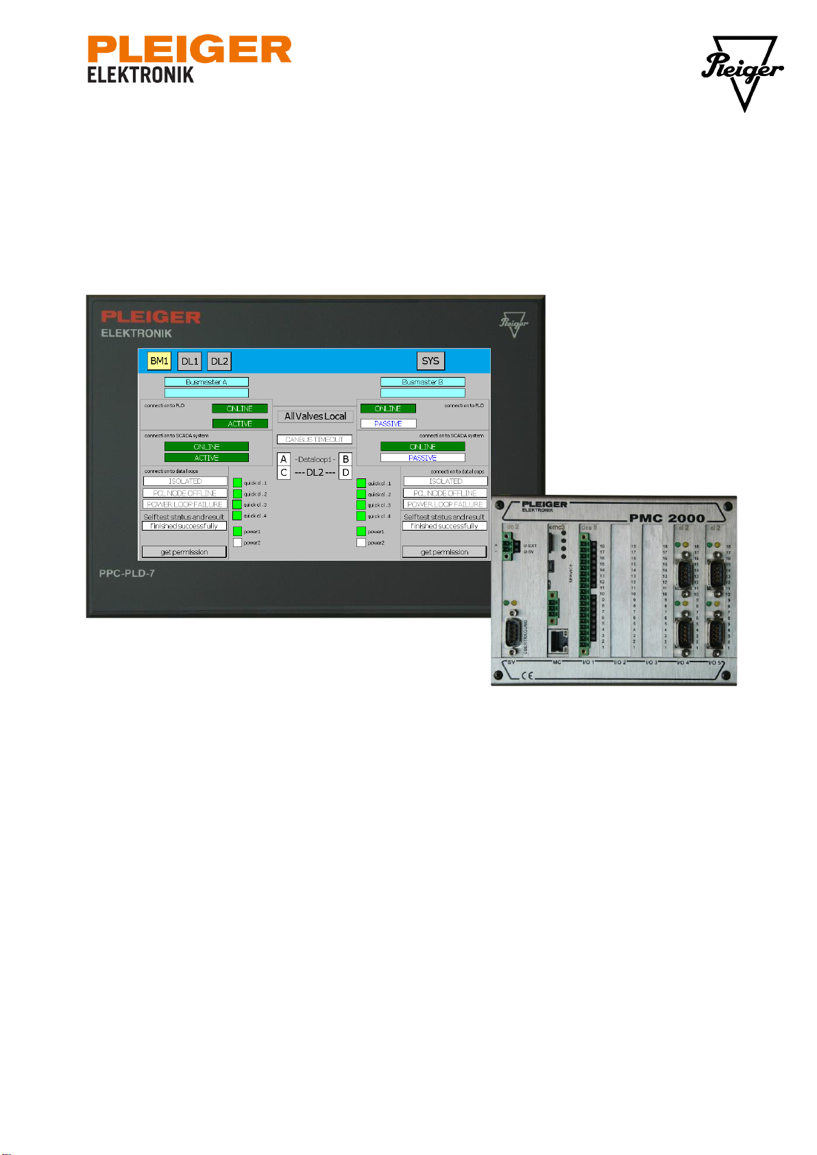
2PCL system overview ...............................................................................5
3The Data Bus System................................................................................6
3.1 PCL Master Function ..........................................................................................................6
3.2 Multiple Data Busses..........................................................................................................6
3.3 Function PCL Slave.............................................................................................................6
3.3.1 The physical layer............................................................................................................6
3.3.2 Data communication and address selection.....................................................................6
4The power bus system..............................................................................8
4.1 Handling power bus faults, interruption............................................................................8
4.2 Handling power bus faults, short circuit ...........................................................................8
4.3 Power Management.............................................................................................................8
4.4 Power Bus Cable.................................................................................................................9
4.4.1 Cable Length ...................................................................................................................9
4.4.2 Reduced current ..............................................................................................................9
4.4.3 Additional supplies...........................................................................................................9
4.4.4 Installation rules...............................................................................................................9
4.5 Fusing................................................................................................................................10
5Valve Control Interface (PCL-VCI)..........................................................11
5.1 Interface to actuator..........................................................................................................11
5.1.1 Quick Closing Operation................................................................................................11
5.2 Valve Control Function.....................................................................................................12
5.2.1 PCL-VCI versions ..........................................................................................................12
5.3 Connection of actuator for hazardous area (CM-ExE)....................................................13
5.4 Technical data PCL-VCI....................................................................................................13
5.4.1 Connector for bus cable.................................................................................................14
5.4.2 EHS connector...............................................................................................................14
5.5 PCL-VCI with extended inputs and outputs (V3-3 and V3-4 (vertical connectors)) ......14
5.5.1 External local indication box...........................................................................................15
5.5.2 External local control box...............................................................................................15
5.5.3 Extended SCADA-Inputs and SCADA-Outputs..............................................................15
5.5.4 Technical data (extended inputs and outputs)................................................................16
5.5.5 Connector (extended inputs and outputs) ......................................................................16
6Bus IO Unit (PCL-IO)...............................................................................17
6.1 Analog / digital inputs.......................................................................................................17
6.2 Isolated digital inputs .......................................................................................................17
6.3 Digital relay outputs..........................................................................................................17
6.4 Technical data PCL-IO ......................................................................................................17
6.4.1 Connector for bus cable.................................................................................................18
6.4.2 Connector for process IO...............................................................................................18
7PCL-Power Control (PCL-PC).................................................................19
7.1 Bus-Master connection and begin of power loop...........................................................19
7.2 Technical description PCL-PC .........................................................................................19
7.3 Power loop interconnection .............................................................................................20

PCL
Pleiger Elektronik GmbH & Co. KG
www.pleigerelektronik.de
Fon +49 2324 398 333
2/ 65
Pleiger Control Loop
Manual version 2018-03
8PCL-Bus connector (PCL-BC)................................................................21
8.1 Technical description PCL-BC.........................................................................................21
9PCL-Master (busmaster).........................................................................22
9.1 General description...........................................................................................................22
9.2 Display elements and interfaces of the mc3 processor board.......................................23
9.3 Busmaster and local operation panel..............................................................................24
9.4 Modbus RTU Interface ......................................................................................................24
9.5 Technical data Busmaster................................................................................................25
10 PPC-PLD for local operation and set-up................................................26
10.1 Startup picture of the PLD................................................................................................27
10.1.1 Possibilities of the operation e.g. command or parameter changes................................28
10.2 Backup operation..............................................................................................................28
10.2.1 PLC-VCI node for an EHS with open close drive ...........................................................29
10.2.2 PLC-IO...........................................................................................................................31
10.2.3 PLC-VCI node for an EHS with continuous drive ...........................................................31
10.2.4 PCL-VCI node with input and output..............................................................................32
10.2.5 Control permission for backup operation........................................................................33
10.2.6 Backup operation for an EHS with open close drive.......................................................34
10.2.7 Backup operation for an EHS with continuous drive.......................................................35
10.2.8 Failure indication............................................................................................................36
10.3 Advanced operation with analyzing function..................................................................38
10.3.1 PLC node.......................................................................................................................40
10.3.2 PLC-VCI node for an EHS .............................................................................................41
10.3.3 PLC-IO...........................................................................................................................41
10.3.4 Control permission for advanced operation with analyzing function ...............................42
10.3.5 Advanced operation for a PCL-VCI................................................................................42
10.3.6 Block a valve..................................................................................................................43
10.3.7 End the blocked state of a valve ....................................................................................43
10.3.8 Modify the parameter Actuator.......................................................................................43
10.3.9 Modify the Auxiliary parameter.......................................................................................44
10.3.10 Modify the parameter runtime.......................................................................................46
10.3.11 Modify the parameter quick close..................................................................................47
10.4 Process picture of the busmaster....................................................................................48
10.4.1 Symbol explanation for the connection to SCADA system .............................................48
10.4.2 Symbol explanation for the connection to PLD...............................................................49
10.4.3 Symbol explanation for the PCL-buses..........................................................................51
10.4.4 General symbols............................................................................................................52
10.5 Selftest function of PCL-System......................................................................................53
10.5.1 Basics............................................................................................................................53
10.5.2 Selftest operation...........................................................................................................54
10.5.3 Selftest failure analysis ..................................................................................................55
10.6 General system failure indication ....................................................................................57
10.7 PLD configuration and service functions........................................................................58
10.8 Technical data PPC-PLD...................................................................................................62
11 Figures.....................................................................................................63
12 Tables ......................................................................................................65

PCL
Pleiger Elektronik GmbH & Co. KG
www.pleigerelektronik.de
Fon +49 2324 398 333
3/ 65
Pleiger Control Loop
Manual version 2018-03
1 General information
This manual contains instructions and drawings for correct handling and using the equipment. Please
observe all instructions of this manual carefully.
Please note that not respecting the information, using the equipment not according the regulations be-
low, wrong installation or incorrect handling could influence personal or plant safety seriously!
This manual is part of this operation resource. Keep the manual safe for later use. The manufacturer
reserves the right to change performance data, specification data or the design layout without an ad-
vance notice.
1.1 Transportation and storage instructions
The equipment must be inspected upon reception for damages that may have occurred
during transportation or handling. If damages are obviously, inform the carrier and the
manufacturer immediately. Dropped components must not be applied because invisible
damages may influence the reliability.
1.2 Installation and electrical connection
The equipment has to be installed by qualified personnel only, that is familiar with the
safety requirements and potential risk. Please note the special safety requirements be-
longing the point of installation, generally accepted rules of technology, the connection
instruction in this manual and the available imprint on the component.
1.3 Intervention into the component
If malfunctions occur or something is dubious please contact the manufacturer. Intervention into the
component could heavily affect the safety of person and plant and will lead to termination of liability and
caveat emptor.
1.4 Intended use
To use the equipment is approved only if the instructions of this manual are complied and the use is
appropriate to the type label and to an application it is intended to.
In the field the technical specifications and denoted limit values have to be generally maintained. This
applies particular with regard to voltage, temperature and other noted environmental conditions. The
use beyond the specified and approved edge conditions could put life at risk, damage the component
or cause secondary damages to the plant.
1.5 Not intended use
Every use of the component that is not equal to the use described in chapter „1.4 intended use“ is
obtained as not intended use. Damages that result from not intended use and / or result from unauthor-
ised intervention on the component, not according to this manual, or not using original spare parts the
claim for warranty and liability of the manufacturer expires.
1.6 Use in safety related vital functions
It is the responsibilityof the user toperform a riskanalysis of the whole installation and to define potential
safety related functions.
It is the responsibility of the user to take care of appropriate measures to achieve the safeness in safety
related vital functions.

PCL
Pleiger Elektronik GmbH & Co. KG
www.pleigerelektronik.de
Fon +49 2324 398 333
4/ 65
Pleiger Control Loop
Manual version 2018-03
1.7 Certificates and Approvals
PCL-system components meet the requirements of the following Directives:
•DNV GL Class Guideline DNVGL-CG-0339 (Nov/2016)
The following approvals apply:
•Type approval TAA00001FM by DNV GL
•Type approval TAA00000S3 by DNV GL (for PPC-PLD-7)
Certificates and approvals can be downloaded from our website or ordered from the manufacturer.
Technical Support:
+49 2324 398 333
service@pleiger-elektronik.de

PCL
Pleiger Elektronik GmbH & Co. KG
www.pleigerelektronik.de
Fon +49 2324 398 333
5/ 65
Pleiger Control Loop
Manual version 2018-03
2 PCL system overview
The PCL (Pleiger Control Loop) is a fault tolerant data and power
bus system. It is primarily intended for use with Pleiger EHS valves
and similar devices. Major benefit of the system is the robustness
against disturbances and damages to the bus cable and other
parts of the system. Even in most cases of severe damage not
more than two drives of the system will fail.
The main components of the PCL System are:
•Redundant, hot standby busmaster, PCL-Master
•The local operation unit, PLD-7
•The PCL node for valve control PCL-VCI
•The PCL node for input and output application PCL-IO
•The power bus connection module PCL-PC
This manual describes some basics of the system, the operation of the busmaster as well as the tech-
nical data of the busmaster and the valve control interface.
Figure 2-1: Sample configuration with supply from single bus master cabinet

PCL
Pleiger Elektronik GmbH & Co. KG
www.pleigerelektronik.de
Fon +49 2324 398 333
6/ 65
Pleiger Control Loop
Manual version 2018-03
3 The Data Bus System
The PCL data bus is a master slave system using a communication protocol similar to the Modbus
protocol but providing special function types and a very tight timing for increased performance. Hereby
a fast data transfer is achieved even at low baud rates. The communication nodes connected to the
data loop are called nodes.
3.1 PCL Master Function
In most applications two independent master controllers (A and B) handle the communication with the
nodes at both ends of the data bus. The polling sequence is the major difference between both bus-
masters. While A is starting with the first node of a data loop counting upwards, B starts with the last
one and then counts downwards.
Note:The sequence used for polling the nodes is parameterised by the user. This sequence must be
identical to the physical sequence of the slave units (EHS) on the bus. Otherwise a proper fault
localisation is not guaranteed.
Both masters are connected via CAN bus. This connection is used to copy any information that one of
the masters receives to the other the other master immediately. Therefore both masters’ data are al-
ways identical.
3.2 Multiple Data Busses
To increase the communication speed and to improve the availability in case of multiple errors each
busmaster can serve up to 8 data loops simultaneously. All data loops have identical functions. The
number of data loop and the nodes connected to each data loop can be selected by several parame-
ters. Each data loop can serve up to 100 nodes and up to 250 nodes may be connected to a busmas-
ter resp. a pair of busmasters. If more than 60 nodes shall be connected to a busmaster at least two
data loops are recommended. Four to eight data loops are recommended for 250 nodes.
3.3 Function PCL Slave
The PCL slave interface is the most important link in the PCL safety chain. It is not only acting as a
communication slave but also takes over the following tasks:
•Separating the data bus loop sections electrically
•Acting as a repeater
•Selecting the valid busmaster
•Control of the actuator resp. operating
3.3.1 The physical layer
Electrically the slaves perform a point-to-point communication on two RS485 ports A and B. Both
ports are optically isolated, overload protected and connected by a simple logic. Special 485 drivers
guarantee a differential output signal with extraordinary high amplitude and an improved signal-to-
noise ratio. Each node acts as a signal repeater.
Because of the additional protection devices even a short circuit between the 230V AC supply and the
data bus will not cause a permanent damage of the slave but of course an interruption of the data link.
For data transmission a shielded twisted pair cable with at least 0,75 mm² cross-section is required.
This twisted pair is part of the PCL bus cable. Other cable types (5x2,5) are going to be tested.
3.3.2 Data communication and address selection
The protocol is quite similar to the Modbus protocol. Only the function types are different and the tim-
ing is faster to achieve optimal performance. The most frequently used message exchange is based
on the master’s status request (4 bytes) and the slave’s status response (6 bytes). Using a baud rate

PCL
Pleiger Elektronik GmbH & Co. KG
www.pleigerelektronik.de
Fon +49 2324 398 333
7/ 65
Pleiger Control Loop
Manual version 2018-03
of 19200 bits/s such a message exchange is handled completely within 9,7ms. A 16 bit CRC in combi-
nation with a parity check is used for error checking.
The node address in the range 1 to 250 is simply set by means of an 8 bit DIP switch. This is a very
simple technique and does not require special skills or equipment during installation or when defective
parts are to be exchanged.
The position ON corresponds to a 1 whereas OFF corresponds to a 0. The
first switch 1 sets the least significant bit and the switch 8 sets the most sig-
nificant bit of the address.
1 2 345 6 78
O
N
O
F
F
Figure 3-1: Address
DIP switch

PCL
Pleiger Elektronik GmbH & Co. KG
www.pleigerelektronik.de
Fon +49 2324 398 333
8/ 65
Pleiger Control Loop
Manual version 2018-03
4 The power bus system
Besides the data communication the bus cable also provides power supply with 230V AC. Similar to
the data bus the power bus is also configured as a loop. Both ends of the loop are protected by the
same 16A fuse. Several power loops may be installed within a single data bus loop.
DANGER
Electrical shock
Mains supply with 230 V AC
•All installations must only be carried out by an electrically qualified person.
•Disconnect the system from the mains and secure it against being switched on un-
intentionally.
•Obey the accident prevention regulations when testing the live system.
4.1 Handling power bus faults, interruption
If one or both conductors of the power bus break the current is still conducted by the both parts of the
power loop. Therefore any kind of interruption is not even noticed by the system. To detect such faults
the system is equipped with a self-test function. Such a self-test has to be performed in regular inter-
vals (see chapter 10.5 Selftest function of PCL-System).
4.2 Handling power bus faults, short circuit
Naturally the effect of a short circuit is much more severe. Because the current is the same within the
whole loop the fuse of this loop will blow and all slaves connected to this loop will fail. Because the
PCL masters supervise the power loop voltage this event is going to be indicated via Modbus connec-
tion immediately.
The fuse may now be reset manually. Of course without any additional measures the fuse would just
blow again. Therefore the master cabinet as well as each slave is equipped with a power relay and a
short circuit snooping device. If a short circuit is detected the power relay stays open. This prevents
that the fuse is blown once again.
Note:If a short circuit is detected on either side of the slave the slave is not connected to the power
bus and therefore stays turned off.
4.3 Power Management
As each valve requires up to 1,8A and the cable is fuse protected with 16A, approximately 8 valves
can run simultaneously. If more than 8 valves shall be connected to a single bus section a power
management is required. This power management assures that not more than 8 valves connected to
the same fuse will run simultaneously. To avoid unacceptable delays it is recommended to limit the
number or valves within one power section to 25…30.
For power management the master adds up all required current in each of up to 10 power loops. A
command is sent to the valve only if the required current for running this drive is still available within
the power loop. Because the start-up current of the valves is significantly higher than the nominal cur-
rent the time between valve starts are at least 100ms.
The maximum required current of each valve as well as the maximum current within each power loop
can be individually parameterised by the user.

PCL
Pleiger Elektronik GmbH & Co. KG
www.pleigerelektronik.de
Fon +49 2324 398 333
9/ 65
Pleiger Control Loop
Manual version 2018-03
4.4 Power Bus Cable
Of course the length of the power bus cable is limited because of the voltage drop on the bus. There-
fore it is necessary to make a rough estimate of the allowed cable length. Please note that this max
length does not concern the data bus but only a single power bus loop.
The max allowed voltage drop on the power bus cable is 20% = 46V. By this and the max current of
8x1,8A = 14,4A the maximum cable length can be determined. Of course the worst case must be
taken into consideration. Therefore it is assumed that the power loop is supplied at one side only. Un-
der normal conditions the bus loop is supplied at both sides and therefore the maximum voltage drop
is reduced to less than 10%. The max allowed conductor resistance is:
Rmax = 46V/14,4A = 3,2Ohm
First it is assumed (worst case) that all 8 drives are mounted directly beneath each other at the end of
the cable.
4.4.1 Cable Length
The max cable length depends on the type of cable used. The EHS bus interface provides 4 terminals
to connect up to 4x2.5mm² power cable. If such a cable is used the max length between the power
supply and the last drive within the power loop is 441m.
Type
Conductors, power loop
Resistance
Length
1
3x1.5 mm²
9.08 mOhm/m
176 m
2
2x2.5mm²
7.26 mOhm/m
220 m
3
4x1,5mm²
6.05 mOhm/m
264 m
4
3x2,5mm²
5.45 mOhm/m
294 m
5
2x4mm²
4.54 mOhm/m
352
6
4x2.5mm²
3.63 mOhm/m
441 m
Table 4-1: PCL bus cable length
Additional power bus loops should be connected via a 2x4mm² or a 2x6mm².
Note:If conductors of a power loop cable are connected in parallel an external connection to Protec-
tive earth with sufficient cross section is required.
4.4.2 Reduced current
If longer cables shall be used the maximum current must be reduced by limiting the number of drives
running concurrently. This can easily be parameterised for each single power loop. The maximum
length may be enlarged by the following factor.:
No of drives
8
7
6
5
4
3
Length multiplier
1
1.14
1.33
1.6
2
2.6
Table 4-2: Cable length multiplier and maximum loop current
4.4.3 Additional supplies
If the max length of the power bus loop is exceeded or the number of drives is more than app. 25-30 a
new power bus loop must be inserted. Therefore an additional cable (4x4mm²) connects the end of
the first power bus loop with its supply within the switch cabinet and the supply of the next power bus
loop with the bus cable vice versa.
4.4.4 Installation rules
The bus cable may be laid parallel to other cables conduction a voltage of 230/400V with a maximum
current of 63A. If current or voltage is above this limit or if the cable is used to connect a drive to a fre-
quency inverter, a minimum distance of 1 m must be kept.

PCL
Pleiger Elektronik GmbH & Co. KG
www.pleigerelektronik.de
Fon +49 2324 398 333
10 / 65
Pleiger Control Loop
Manual version 2018-03
Both ends of the bus loop or of a power loop should be laid in separate paths to avoid a damage of
both ends at the same time. If the outer hull of the cable is damaged the cable must be replaced. This
holds true even if the damage is diminutive.
4.5 Fusing
Each power bus loop must be fused separately with two 16A automatic fuses with B characteristic.
Attention: Fuses with different characteristic or different design current must not be used!
CAUTION
Material damage
Wrong system design, wrong installation, incorrectly connected drives or defective ca-
bles may cause damage to the PCL-System-Components!

PCL
Pleiger Elektronik GmbH & Co. KG
www.pleigerelektronik.de
Fon +49 2324 398 333
11 / 65
Pleiger Control Loop
Manual version 2018-03
5 Valve Control Interface (PCL-VCI)
The data interface, the short circuit detection as well as the valve control
unit are implemented on a single PCB the PCL-VCI (Valve Control Inter-
face). This board may either be integrated in the drive’s case or may be
installed in a separate bus box.
5.1 Interface to actuator
Two relays, two binary inputs and one analogue 4..20mA input form the
interface to the valve drive. Additionally the board also supplies the limit
switches and eventually the analogue feedback unit of the drive. The sup-
ply voltage is 15..27V at 30mA maximum.
One of the two relays is always used as a make contact whereas the
second one can be switched to two different operational modes by means
of an additional solenoid valve supply switch (S1).
1. make contact switching the 230VAC of the power bus (standard)
2. break contact switching an external supply voltage of 230V AC(or
24V DC) (S1 in position “quick close”)
Operation mode 1 is the standard one (& delivery status).
Mode 2 is used for single acting valves that must stay open in case of a
power fail or such valves that belong to a separately hard-wired quick
close system. If the external supply voltage is turned off the valve will
close in any case.
5.1.1 Quick Closing Operation
The PCL system uses two different ways to connect the drives to a quick closing system:
1. Software Control:
The quick close signal is collected by the busmaster by means of one or more digital inputs
(24V = normal operation, 0V = quick close). In case of a “quick close state” a close command
is sent to all nodes that belong to this quick close system. This of course requires that the data
transfer function of the system is working properly.
2. Hardware Control:
The quick close signal is hard wired to each drive of the quick close system. This wiring is
used to supply the magnetic valve within each single acting drive. If this supply voltage is
turned off, the drive will close regardless of the proper function of the data communication sys-
tem.
CAUTION
Malfunction / Material damage
Take care that the S1 switch is in “standard” position if no external 24V DC or inde-
pendent 230V AC quick close supply is connected. If an external supply voltage is con-
nected to X2.10 & X2.11, the switch must be in “quick close” position!
A proper actuator configuration for the VCI-card is a mandatory requirement, too!
A wrong configuration or wrong switch setting can cause malfunctions or defective to
the PCL-VCI, the connected actuator or feedback modules!
Figure 5-1: PCL-VCI-card
3-3 (with extended in- &
outputs)

PCL
Pleiger Elektronik GmbH & Co. KG
www.pleigerelektronik.de
Fon +49 2324 398 333
12 / 65
Pleiger Control Loop
Manual version 2018-03
5.2 Valve Control Function
The kind of control algorithm is determined by the PCL master on slave start-up (if the actuator isn’t
operated by local control box
1
). At present 17 different actuator types are supported:
Abbreviation Description
EHS_D standard double acting valve
EHS_DK double acting valve operating in continuous mode
EHS_SO single acting valve, spring open
EHS_SC single acting valve, spring close
EHS_SOK single acting valve, spring open, operating in continuous mode
EHS_SCK single acting valve, spring close, operating in continuous mode
EHS_SCO single acting valve, spring close with mechanical override
EHS_SOO single acting valve, spring open with mechanical override
MOV standard motor valve
QC_SC single acting valve, spring close, with external quick close circuit
QC_SO single acting valve, spring open, with external quick open circuit
EHS_SCH single acting valve, spring close with electro-hydraulic override
EHS_DQ double acting valve with separated hydraulic unit
EHS_SCQ single acting valve with separated hydraulic unit, requires additional relay
QC_SCQ single acting valve with separated hydraulic unit, requires additional relay
external coil supply for quick closing function required
EHS_DEx double acting valve for use in hazardous area, requires additional CM-ExE module
EHS_DKEx double acting valve for use in hazardous area with analog feedback, requires addi-
tional CM-ExE module
EHS_DOS double acting valve, opening in two steps (time adjustable by auxiliary parameters)
EHS_SC_Step single acting valve, spring close with step close function
EHS_SCO2 single acting valve, spring close with hydraulic override
Type QC_SC and QC_SCK are especially intended for valves within a quick close system.
5.2.1 PCL-VCI versions
Up to hardware version 3 only 14 actuator types have been supported (up to EHS_DEx).
The actuator type EHS_SCO is only implemented in VCI-cards type 1 / 2 up to firmware v3.1. It’s no
more implemented in v3.5 and newer!
To handle actuator type EHS_SC_Step a card with v3.7 (or newer) is recommended.
If one of the valve types greyed in the upper list should be operated, please contact the Pleiger El-
ektronik GmbH for further information.
1
Actuators with VCI cards v3-3 / v3-4 can be operated with a local control box independent of the
state of the PCL master. Therefore the last valid actuator configuration is saved by the VCI card.

PCL
Pleiger Elektronik GmbH & Co. KG
www.pleigerelektronik.de
Fon +49 2324 398 333
13 / 65
Pleiger Control Loop
Manual version 2018-03
5.3 Connection of actuator for hazardous area (CM-ExE)
The double action valve for use in hazardous areas requires an additional CM-ExE module between
PCL-VCI and actuator. PCL-VCI and CM-ExE module must be operated in safe area.
open
close
N
PCL-VCI
9
7
8
4
5
1
2
3
16
15
14 CM-ExE
auxiliary winding
main winding
6
5
4
3
2
1
EHS-D3Ex
Figure 5-2: Connection diagram of CM-ExE
5.4 Technical data PCL-VCI
The boards are equipped with an 8- / 10-fold DIP switch to select the node address and (if available)
the function of the scada inputs onboard.
The position ON corresponds to a “1” whereas OFF corresponds to a “0”. The
first switch sets the least significant bit and switch 8 sets the most significant
bit of the address.
See also chapter 3.3.2 “Data communication and address selection”
and 5.5.5 “Connector (extended inputs and outputs)” for further information!
This board provides two (three in V3-3 and V3-4 with extended I/O (see chapter 5.5)) screw plug con-
nectors to connect the bus cable and the EHS itself. This board may either be integrated in the actua-
tor casing or encased separately in a so called bus box.
Power supply AC
230V 20%, 45-65Hz
max. current on power bus
16Arms
current to detect a short circuit
≤ 10mA
Power consumption (without drive)
without optional I/O
with optional I/O
max. 3W (typ. 2,5W / 3,3VA)
max. 5W
Power supply
for feedback sensors (VCI V2)
for feedback sensors (VCI V3-1 / V3-2)
for analog inputs & outputs (VCI V3-3 / V3-4)
15-27VDC, max. 30mA
20-23VDC, max. 30mA
20-23VDC, max. 25mA
Nominal current of drive
max. 2A
Ambient temperature (casing)
-25°C…55°C
Table 5-1: Technical data PCL-VCI card
1 2 345 6 78
O
N
O
F
F
Figure 5-3: Address DIP
switch

PCL
Pleiger Elektronik GmbH & Co. KG
www.pleigerelektronik.de
Fon +49 2324 398 333
14 / 65
Pleiger Control Loop
Manual version 2018-03
5.4.1 Connector for bus cable
predecessor
Pin
Meaning
successor
5 + 6
1 + 2
Power bus L1, A side
7 + 8
3 + 4
Power bus L2, A side
5 + 6
Power bus L2, B side
1 + 2
7 + 8
Power bus L1, B side
3 + 4
11
9
Data bus -, A side
12
10
Data bus +, A side
11
Data bus -, B side
9
12
Data bus +, B side
10
Table 5-2: PCL-Bus connection table PCL-VCI-card
NOTICE
Phase direction of power supply
Please note that each node will turn the phase of the power bus by 180°.
See chapter 7 “PCL-Power Control (PCL-PC)” for details (including wiring diagrams).
5.4.2 EHS connector
Pin
I/O
Meaning
1
in
Feedback open, make contact to 0V
2
in
Feedback closed, make contact to 0V
3
in
Analogue position feedback, +4..20mA
4
out
Supply sensor, 24V
5
out
Supply sensor, 0V
6
out
Power bus L1
7
out
Function close L2
8
out
Power bus L1
9
out
Function open L2
10
in
External magnetic valve supply (quick close)
11
in
External magnetic valve supply (quick close)
Table 5-3: PCL-VCI-card EHS connector
5.5 PCL-VCI with extended inputs and outputs (V3-3 and V3-4 (vertical
connectors))
The extended version of the VCI provides some extra features. Most important are the additional in-
puts and outputs that may be used for different purposes. The power supply is based on a primary
switched power supply that is smaller, less heavy, more powerful and more efficient. This supply pro-
vides enough power to feed two more 0…20mA inputs and two additional outputs, each providing
30mA at 24VDC.
Because of the slightly reduced size und variable mounting of the terminals the VCI may be adapted
to other casings more easily. Anyhow the mounting of the VCI stays the same.
The inputs can be configured as analog or digital inputs. They are primarily intended to read up to two
sensors like tank content or pump pressure level switches when configured as digital inputs. The digi-
tal outputs may be used for pump control etc. The analog inputs are suitable for passive two wire sen-
sors and the digital inputs require dry contacts. The digital outputs are of PNP type (recovery diode
protected). The required 24VDC supply voltage is also provided by the VCI card.

PCL
Pleiger Elektronik GmbH & Co. KG
www.pleigerelektronik.de
Fon +49 2324 398 333
15 / 65
Pleiger Control Loop
Manual version 2018-03
The meaning of in- and outputs are configured via the Master_Bus.pcl file of this system. If changed
the busmaster transfers the (new) configuration to the nodes.
5.5.1 External local indication box
If external lamps should be used for signaling the actuator state, 2 lamps or LEDs could be connected
via X5. The lamp/LED connected to “Out1” is used for the “close” signal, “Out2” for the “open” signal.
Depending on the configuration (via busmaster) the lamps can signalize final positions only or a mov-
ing actuator, too.
5.5.2 External local control box
In some applications it is required to control a valve locally by means of two digital inputs and to indi-
cate the position by two outputs that may drive a LED. The above mentioned inputs and outputs can
be used for this purpose if the VCI is set to the applicable mode.
The behavior of the VCI card depends on the configured mode and button- or (key) switch-state.
•Both inputs can be used in “normal” or “inverted” mode. Depending on the parameters they are
used active high (standard) or active low.
•If local buttons are parametrized, pressing any button sets the actuator (the VCI-card) in “local
mode” and the VCI handles the signal as immediate open or close command. Further drive com-
mands from the PLD or a SCADA system will be refused!
There are two possibilities to return to “remote mode” (standard):
1) There is a “local release command”, that can be send from the SCADA system or any PLD.
2) By pressing both buttons (open & close) simultaneously for ~2 seconds. Returning to “remote
mode” by this way is signalized by illuminating both external feedback lamps for ~5 seconds.
•If one or two local key switches are used and parametrized, the behavior is quite different:
The actuator will be in “local mode” as long as one key switch is active. All commands from SCADA
system and PLD(s) are refused, even the “local release command” won’t have an effect! Switching
the key switch(es) “off” again (no input active) returns to “remote mode” immediately!
CAUTION
Malfunction
If one(more) actuator(s) is(are) used in local mode, automatic functions like healing,
water treatment or something like that might be disturbed!
DANGER
Serious injuries
The local mode (especially with key switches) will hold the position open or closed to-
tally independent of the state of the SCADA system or the busmaster(s). That could be
important for service and maintenance.
But if it’s an e.g. spring close actuator and no bus power is available (switched off or
power failure) any not predetermined position (e.g. “close” if spring close) can’t be
held! The valve will close for example!
5.5.3 Extended SCADA-Inputs and SCADA-Outputs
If no local control is needed, the In- and Outputs can be used independent from the actuator under
control of the SCADA-system.
•The extended inputs can collect up to two digital or analog signals. These signals are read together
with the drive and error state by the busmaster and written into data registers that could be read by
the SCADA-system.

PCL
Pleiger Elektronik GmbH & Co. KG
www.pleigerelektronik.de
Fon +49 2324 398 333
16 / 65
Pleiger Control Loop
Manual version 2018-03
•Up to two digital outputs can be controlled by the SCADA system in the same way. If the equivalent
bit in the register is set, the output on the VCI card will be set until the bit in the register is reset
again. Depending on the parameters the outputs can be also set to 0 if the communication from the
VCI to the busmaster(s) fails for more than 5s!
NOTICE
Combinations and parameters for extended inputs and outputs
Not every combination of functions of inputs and outputs can be realized!
For example, one key switch and one button can’t be combined to be used as local
control unit but, as another example, it is possible to use both ouputs for local indica-
tion and both inputs to collect digital or analog sensor signals for the SCADA-system.
5.5.4 Technical data (extended inputs and outputs)
Analog Inputs
input range
0…20mA
input resistor
100 Ohm
resolution
12 Bit
precision
max ±0,4% of measuring range, typ. ±0,2%
Digital Inputs
threshold
9…12VDC
max. input current
5mA
Digital Outputs
PNP type, max. 50mA each, no short circuit protection
Operating Temperature
-25°C ... 55°C
Table 5-4: PCL-VCI v3: technical data of extended in- and outputs
5.5.5 Connector (extended inputs and outputs)
Pin
I/O
Meaning
Local Control Function
1
in
input 1, 0…20mA or +24V
Mimic Close Input
2
24V
supply voltage 19…22VDC
3
in
input 2
Mimic Open Input
4
24V
supply voltage 19…22VDC
5
out
PNP output max. 20mA
Feedback Close Out (0V = Close)
6
out
PNP output max. 20mA
Feedback Open Out (0V = Open)
Table 5-5: Connector PCL-VCI v3 extended in- and outputs
CAUTION
Malfunction / Damage
Take care that the DIP-Switches 9 & 10 are only in “ON”-Position, if the equivalent in-
put is used with an analog 4-20mA signal! In case of external switches or digital sensor
signals, the switch has to be “OFF” (factory setting)!

PCL
Pleiger Elektronik GmbH & Co. KG
www.pleigerelektronik.de
Fon +49 2324 398 333
17 / 65
Pleiger Control Loop
Manual version 2018-03
6 Bus IO Unit (PCL-IO)
The PCL-IO is used to acquire
digital and analog data via the
PCL system. Additionally con-
trol commands can be sent to
the process by means of two
relays. The PCL-IO provides
the same bus interface like the
PCL-VCI. All safety features of
the PCL are also implemented.
The PCL-IO is encased into a
waterproof (up to IP68) casing.
Water tight cable fittings are
used for the complete cabling.
6.1 Analog / digital in-
puts
The PCL-IO provides 8 analog inputs with an input range of 0..20,4mA. The internal resistance of
each input is 100Ohm. The inputs are not isolated from one another and therefore only suited for float-
ing current sources like pressure or temperature sensors. The PCL-IO also provides 24VDC to supply
the sensors. Self-resetting fuses protect the inputs against overload due to short circuit in the sensor
cabling.
An 8-fold switch on the board is used to configure the input either as analog or digital. If an input is
used as digital input a 24V input signal is converted to a 4mA current. Please note that these input
must only be used for floating signal sources like liquid level switches, relays etc.
current input = switch position ON
digital input = switch position OFF
CAUTION
Malfunction / Damage
Take care that the DIP-Switches are only in “ON”-Position, if the equivalent input is
used with an analog 4-20mA signal! The delivery state is “OFF”!
6.2 Isolated digital inputs
Additionally each PCL-IO provides two opto-isolated inputs. Both inputs have common 0V.
6.3 Digital relay outputs
For control purposes each PCL-IO is equipped with two relay outputs. Both contacts of a normally
open relay are connected to separate terminals.
6.4 Technical data PCL-IO
Power supply AC
230V 20%, 45…65Hz
max. power loop current
16Arms
current to detect a short circuit
<= 10 mA
Power consumption
max. 6W
Power supply for ext. sensors
24VDC 0,7V, max. 200mA
Max error of analog inputs
max. ±0,4% of full range
Trigger level of digital inputs
12V ±2V
Ambient temperature (casing)
-25°C ... 55°C
Figure 6-1: PCL-IO-card

PCL
Pleiger Elektronik GmbH & Co. KG
www.pleigerelektronik.de
Fon +49 2324 398 333
18 / 65
Pleiger Control Loop
Manual version 2018-03
Table 6-1: Technical data PCL-IO modules
6.4.1 Connector for bus cable
predecessor
Pin
Meaning
successor
5 + 6
1 + 2
Power bus L1, A side
7 + 8
3 + 4
Power bus L2, A side
5 + 6
Power bus L2, B side
1 + 2
7 + 8
Power bus L1, B side
3 + 4
11
9
Data bus -, A side
12
10
Data bus +, A side
11
Data bus -, B side
9
12
Data bus +, B side
10
Table 6-2: PCL-Bus connection table PCL-VCI-card
NOTICE
Phase direction of power supply
Please note that each node will turn the phase of the power bus by 180°.
See chapter 7 “PCL-Power Control (PCL-PC)” for details.
6.4.2 Connector for process IO
Pin
I/O
Meaning
1
in
analog / digital input 1
2
+24V
3
in
analog / digital input 2
4
+24V
5
in
analog / digital input 3
6
+24V
7
in
analog / digital input 4
8
+24V
9
out
relay output 1, make
10
out
relay output 1, make
11
out
relay output 2, make
12
out
relay output 2, make
13
in
analog / digital input 5
14
+24V
15
in
analog / digital input 6
16
+24V
17
in
analog / digital input 7
18
+24V
19
in
analog / digital input 8
20
+24V
21
0V
22
in
- common, isolated digital inputs
23
in
+ isolated digital input 9
24
in
+ isolated digital input 10
Table 6-3: PCL-IO-card process signal connector

PCL
Pleiger Elektronik GmbH & Co. KG
www.pleigerelektronik.de
Fon +49 2324 398 333
19 / 65
Pleiger Control Loop
Manual version 2018-03
7 PCL-Power Control (PCL-PC)
PCL-PC is a short circuit snooping device in a separate casing. This device is used inside the bus-
master cabinet to feed the power bus. One device is required at each end of each power loop. The
function is the same like the circuitry used on the PCL-VCI / -IO. A separate input is used to turn off
the power bus. The correct supply of the power loop is indicated by a green LED.
7.1 Bus-Master connection and begin of power loop
Figure 7-1: Connection of a PCL-PC module the Busmaster and the first two nodes in the PCL-
Loop
7.2 Technical description PCL-PC
Pin layout PCL-PC (Version 9321209840):
Pin
I/O
Meaning
1
in
Power supply L1, A side
2
in
3
in
Power supply L2, A side
4
in
5
out
Power bus L2, B side
6
out
7
out
Power bus L1, B side
8
out
9
out
Make contact, supply OK
10
out
Make contact, supply OK
11
in
0V, turn off power supply
12
in
24V, turn off power supply
Table 7-1: PCL-PC connector
To understand the principal of the PCL-Bus-Power-supply you have to know, that all components that
are part of the PCL-Power-Bus (PCL-PC, PCL-BC, PCL-VCI & PCL-IO) use a circuit controlling tech-
nique as described above. A side effect is, that all modules turn the phases by 180°!
This manual suits for next models
1
Table of contents