Evoqua Wallace & Tiernan W3T170339 User manual

WALLACE & TIERNAN®SENSOR MEASURING MODULES
AND RETROFIT KITS FOR MFC
INSTALLATION MANUAL

2WT.050.580.001.DE.IM.0714
Sensor measuring modules for MFC

Sensor measuring modules for MFC Contents
3
Contents
1. Introduction 5
1.1 Documentation 5
1.1.1 Target groups 5
1.2 Conventions 5
2. General safety instructions 7
2.1 Intended use 7
3. Description 9
3.1 Version 9
3.1.1 Sensor measuring modules 9
3.1.2 Plug in cards for retrofit kits 9
3.2 Description 10
3.2.1 General 10
4. Installation 13
4.1 Opening the housing 13
4.2 Installing and wiring plug-in card 1 to 7 15
4.3 Installing IR board 18
4.4 Connecting the sensor cable 19
4.5 Inserting and connecting the sensors 20
4.6 Mounting the housing covers 22
4.7 Switching the unit on 22
4.8 Firmware update 23
4.8.1 lAP download description 24
5. Wiring Diagram 27
6. Index 35

4WT.050.580.001.DE.IM.0714
Contents Sensor measuring modules for MFC
Sensor measuring modules for MFC Introduction
1.
5
1. Introduction
1.1 Documentation
1.1.1 Target groups
This documentation provides installation and
maintenancepersonnel with the information needed to install and
retrofit the unit.
All persons working with thesensor measuring module and retrofit
kits must have read and understood the instruction manual,
particularly the safety instructions.
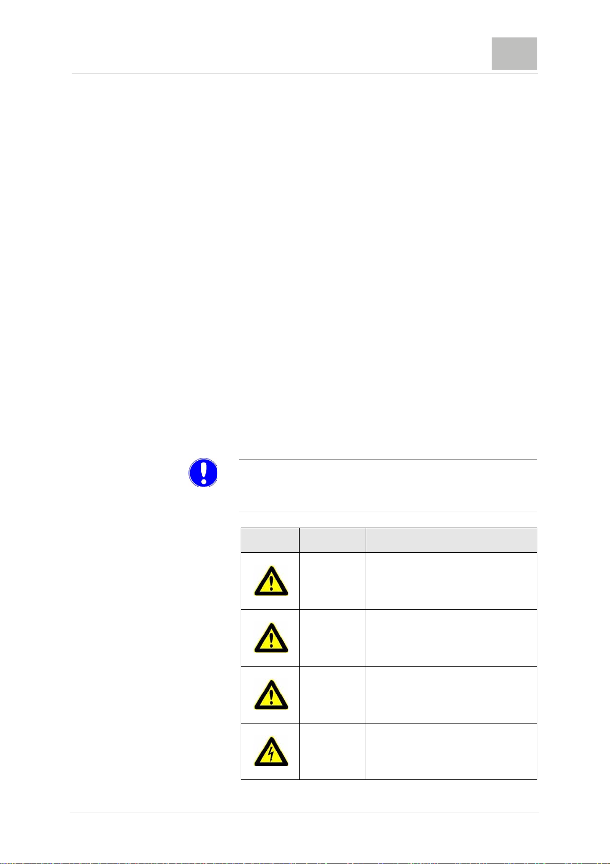
1.2 Conventions
Please note
The different weighting assigned to the various notes in this
manual is indicated by means of pictogram symbols.
Icon Note Signification
Danger! Imminent danger to life and limb;
failure to remedy the situation will
lead to serious or fatal injury.
Warning! Danger to life and limb; failure to
remedy the situation may lead to
serious or fatal injury.
Caution! Failure to observe this information
may lead to moderately serious or
minor injury or material damage.
Warning! Danger of electric shocks.

6WT.050.580.001.DE.IM.0714
Introduction Sensor measuring modules for MFC
1.
Please note These notes facilitate work with the
unit.
Icon Note Signification

Sensor measuring modules for MFC General safety instructions
2.
7
2. General safety instructions
2.1 Intended use
Thesensor measuring modulesand retrofit kitsare designed tobe
installed in the MFC control unit.
The operational safety of the sensor measuring modules and
retrofit kits can onlybe guaranteed solong as they are used strictly
as intended. They may only be used for the purpose defined in the
order and under the operating conditions indicated in the
technical specifications. Modifications to the sensor measuring
module and retrofitkits which go beyond those described in this
manual are not permitted.
Compliance with the intended use also includes reading this
instruction manual and observing all the instructions it contains.
The operator bears full and sole responsibility if this unit is put to
any use which does not comply strictly and exclusively with this
intended use.

8WT.050.580.001.DE.IM.0714
General safety instructions Sensor measuring modules for MFC
2.
2.2 General safety instructions
Evoqua Water Technologies GmbH places great emphasis on
safety when work is performed using the sensor measuring
modules and retrofit kits. Safety is our guiding principle right from
the design phase; the system is therefore equipped with safety
features.
Safety instructions The safety instructions in this documentation must be observed
unconditionally at all times. Additional industry-wide or in-house
safety regulations also continue to apply.
State-of-the-art technology The sensor measuring modules and retrofit kits were constructed
in accordance with the state of the art and all recognized technical
regulations relevant to safety. However, if the unit is used by
untrained personnel, potentially fatal hazards may occur for the
user or third parties during use of the unit, and damage to the
sensor measuring modules, retrofit kits and other equipment may
also result.
Worknotspecifically describedin this instructionmanualmayonly
be performed by authorized personnel.
Personnel The operator running the systemmust ensure that only authorized
and qualified specialists work with and on the system and only
within their assigned areas of responsibility. "Authorized
specialists" refers to trained technicians of the operator, Evoqua
Water Technologies GmbH and, if applicable, the service partner.
Only qualified electricians may perform work on electrical
components.
Spare parts / components Correct operation of the sensor measuring modules and retrofit
kits is only guaranteed if original spare parts and components are
used in the combinationdescribed in this Operating Manual. If this
stipulation is not observed, there is the risk of malfunction or
damage to the sensor measuring modules and retrofit kits
Extensions and conversions The system must not, without the express, prior, written consent of
the manufacturer, be modified, extended, or converted in any way
that might adversely affect its safety.
Electrical power During normal operation, the MFC must remain closed.
Switch off the complete system and secure against reactivation
prior to installation, inspection, maintenance and repair work.
Connect cables in accordance with the terminal diagrams.
Please note
For more information, including the general safety instructions,
please review the instruction manual „MFC”.

Sensor measuring modules for MFC Description
3.
9
3. Description
Due to the MFC's modular design, simple retrofitting and
configurationof sensormeasuringmodules in accordancewith the
plug-and-play principle is possible at any time.
Different versions are available.
3.1 Version
3.1.1 Sensor measuring modules
W3T170339 Total chlorine TC1
W3T170341 Total chlorine TC1-S
W3T170343 Free chlorine FC1
W3T170345 Chlorine dioxide CD7
W3T170347 Ozon OZ7
W3T166292 pH
W3T166165 Redox
W3T166293 Fluorine (F-)
W3T158763 Conductivity 600 µS
3.1.2 Plug in cards for retrofit kits
W3T158761 Cl2- DEPOLOX®5
W3T158762 Cl2- DEPOLOX®4 (PT100)
W3T166161 mA/V input
W3T166162 4x mA output
W3T170020 Relay (eight-way)
W3T166240 Infrared interface
10 WT.050.580.001.DE.IM.0714
Description Sensor measuring modules for MFC
3.
3.2 Description
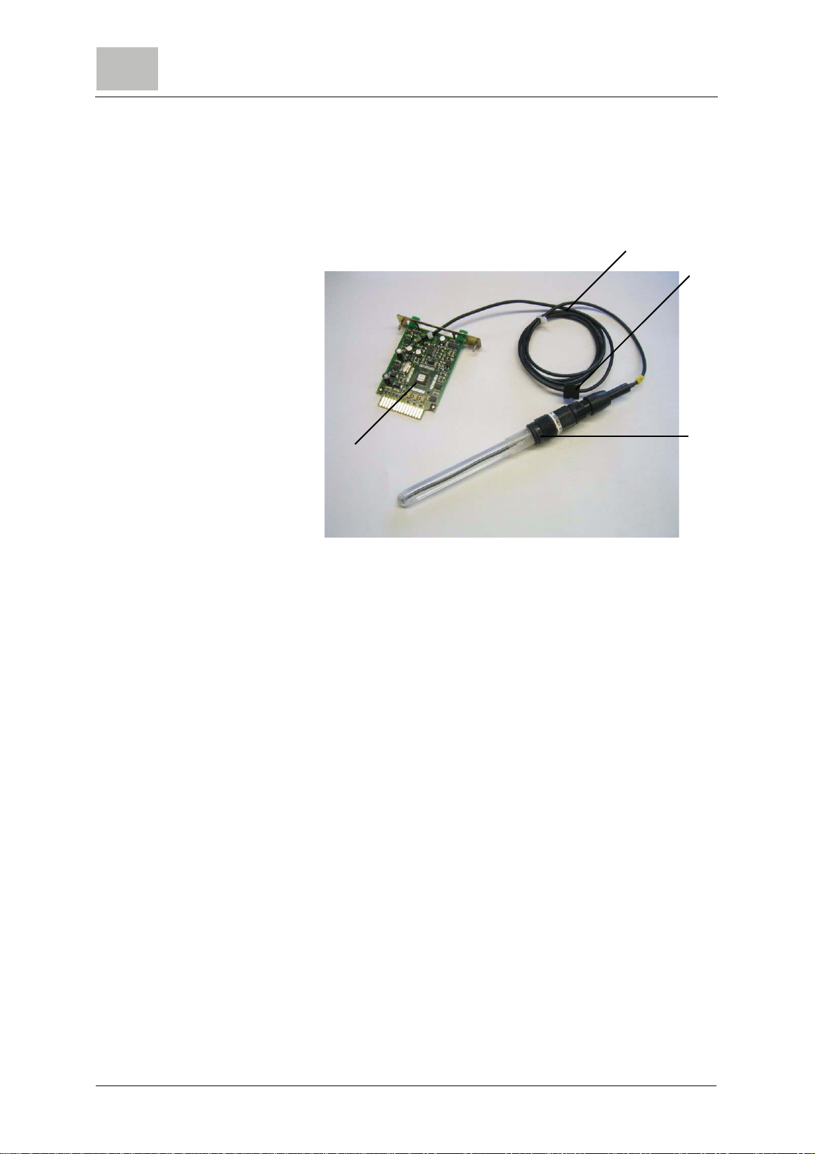
3.2.1 General
A Sensor cable
B Housing duct
C Sensor
D Plug-in card
Sensor measuring module The sensor measuring module consists of:
• Sensor (C) (not in 3 electrode cells,
mA/V input)
• Sensor cable (A) with watertight housing cable
duct (B) (not in 3 electrode cells,
mA/V input)
• The pre-calibrated plug-in card (D)
Due to the MFC's modular design, simple retrofitting and
configurationof sensormeasuringmodules in accordancewith the
plug-and-play principle is possible at any time.
A
B
C
D

Sensor measuring modules for MFC Description
3.
11
In principle, the following sensor measuring module types or
retrofit kits can be installed in module slots 1 to 4:
DES - for DEPOLOX®5 flow block assembly
DES - for DEPOLOX®4 flow block assembly with
PT100 temperature option
DES - for membrane sensors: free chlorine FCI,
chlorine dioxide (CD7), ozone (OZ7), total chlorine
TC1
pH - pH value
mV - Redox value
F-- Fluoride value
mS - Conductivity
mA/V - Input module
Depending on the selected application, the menus are initialized
according to the installed sensor modules when the device is
switched on. See Instruction Manual „MFC” Chapter 4.4
"Applications".
Sensor measuring module 1
(MOD 1) Sensor measuring module 1 is regarded as the main
measurement and therefore has the most controller functions
(ratiocontrol, single feedback close-loop control or combi-control).
No controller output is available for application 1.
Sensor measuring module 2
(MOD 2) Depending on the application, sensor measuring module 2 has
eitherasinglefeedbackclose-loopcontrol(application3),twotime
switch contacts (application 4) or it is used to optimize the
controller setpoint in sensor module 1 (application 5).
Module slot 5
(MOD 5) Module slot 5canonlybe equipped with amA/Vsensormeasuring
module, which is used to record further process parameters such
as flow rate or external setpoint/dosing factor.

12 WT.050.580.001.DE.IM.0714
Description Sensor measuring modules for MFC
3.
Module slot 6
(MOD 6) As an option, module slot 6 can be equipped with a four-way mA
output card. Each mA output can be optionally assigned with a
measured value or also with a controller control signal
(Ym feedback / Yout).
Module slot 7
(MOD 7) Module slot 7 is equipped with an eight-way relay card. Depending
on the application, controller output and selected alarm
assignment, the relays are assigned different functions.
Please note
Afterthemoduleshavebeen installed, the applicationsettingmust
be reviewed and edited if necessary (see Instruction Manual
„MFC„ Chapter 4.4 "Application".
Furthermore, the controller settings, measuring ranges and other
operating parameters must be reviewed and edited if necessary
(see Instruction Manual „MFC”).
The sensors must calibrated after installation.
Sensor measuring modules for MFC Installation
4.
13
4. Installation
4.1 Opening the housing
1 Remove the housing cover of the flow block assembly by
pressing the two buttons on the top of the housing.
Please note
(Not required for retrofitt kits without sensors)
2 Release the five screws on the cover of the electronic module.
The indication and operating elements on the cover of the
electronic module are connected to the housing with wires.
Please note
The unit automatically switches off when the cover is removed.
3 Carefully remove the electronic module cover and hang on the
strain relief.
14 WT.050.580.001.DE.IM.0714
Installation Sensor measuring modules for MFC
4.
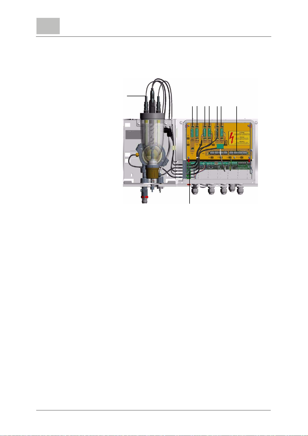
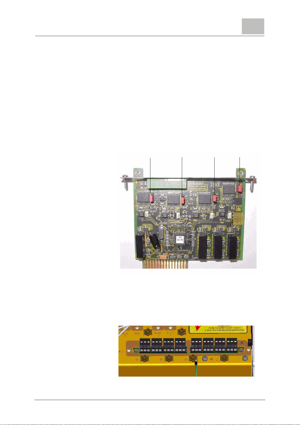
Arrangement of
the plug-in cards and cables Example using the combination chlorine/pH/conductivity/Cl-N
A mA-out plug-in card (mod 6)
B mA/V input plug-in card (mod 5)
C CI-N plug-in card (mod 4)
D Conductivity plug-in card (mod 3)
E pH plug-in card (mod 2)
FCl
2plug-in card (mod 1)
G Relay plug-in card (mod 7)
H Infrared board
I Module identification 1-4
Any sensor measuring module can be installed in slot C (mod 4),
slot D (mod 3), slot E (mod 2) and slot F (mod 1).
A B C D E F G
H
I

Sensor measuring modules for MFC Installation
4.
15
4.2 Installing and wiring plug-in card 1 to 7
1 Remove the slot's dummy cover.
Save for later use!
2 Insert and screw in the plug-in card.
3 If necessary, wire the sensor cable terminal strip and insert
into the plug-in card.
4 Attach the module identificaiton (I) on the cable according to
the module slot (mod 1 = 1, mod 2 = 2, mod 3 = 3 and
mod 4 = 4).
The respective wiring diagrams are listed in Chapter 5. “Wiring
Diagram" on page 27 or in the Instruction Manual „MFC” "Wiring
Diagrams".
"DES" module for DEPOLOX®5
and/or DEPOLOX®4and
PT100
Terminal assignment:
1: Red (WRK)
4: White (REF)
5: Blue (CNT)
Shield: Black
Depending on the module slot, the included plug must be used for
connection on the left or right side.
Terminal assignments for plug-in card with PT100:
"pH" module
Please note
The sensor cable is already wired with pH plug-in card!
"mV" module
Please note
The sensor cable is already wired with mV plug-in card!
"F-" module
Please note
The sensor cable is already wired with F-plug-in card!

16 WT.050.580.001.DE.IM.0714
Installation Sensor measuring modules for MFC
4.
"DES" module for membrane
sensors TC1, FC1, CD7, OZ7 Terminal assignment:
1: Red
2: White
3: Blue
Shield: Black
Depending on the module slot, the included plug must be used for
connection on the left or right side.
"mS" module Terminal assignment:
1: Grey
2: White
3: Red
4: Blue
5: Yellow
6: Brown
"mA/V" module during
installation
as mod 1 to 4
Terminal assignment:
1: Measurement input 0 – 10 V
or
2: Measurement input 0/4 – 20mA
3: GND
"mA/V" module during
installation
as mod 5
Terminal assignment:
1: Measurement input 0 – 10V - Flow Wq
or
2: Measurement input 0/4 – 20mA - Flow Wq
3: GND - Flow Wq
4: Measurement input 0/4 – 20 mA - ext. setpoint and/or
dosing factor
5: GND - ext. setpoint and/or dosing factor
Sensor measuring modules for MFC Installation
4.
17
"mA out" module for
installation as mod 6 • All mA outputs can be assigned as desired:
Cl2, pH, Redox, Cl-N, conductivity, temperature, Ym/Yout
(See Instruction Manual „MFC” under "Input/Output" - "Analog
Output 1/2 or 3/4" Menu 1.5.)
• Load can be switched over 400 Ohm / max 1000 Ohm
Reset the respective bridge on the plug-in card:
L: < 400 Ohm / H: < 1000 Ohm
Plug terminal assignment:
mA-Out 1: Terminal 7: + / terminal 8: -
mA-Out 2: Terminal 5: + / terminal 6: -
mA-Out 3: Terminal 3: + / terminal 4: -
mA-Out 4: Terminal 1: + / terminal 2: -
A mA-Out 1 - load switch over
B mA-Out 2 - load switch over
C mA-Out 3 - load switch over
D mA-Out 4 - load switch over
Eight-way relay module
to install as mod 8 Wiring diagram for application 1 - 5, see appendix or Instruction
Manual „MFC”.
A C D
B

18 WT.050.580.001.DE.IM.0714
Installation Sensor measuring modules for MFC
4.
4.3 Installing IR board
Please note
IR boards can be operated with all MFC firmware versions.
A Slot for IR module
View inside the housing with IR board
BNut
C IR board
D Housing slot
A
B
C
D

Sensor measuring modules for MFC Installation
4.
19
C IR board
D Housing slot
EScrew
F Pin contact strip
GPlug
H Spacing bolt
I IR window
1 To simplify installation of the IR board (C), first remove the
plug (G) and insert the IR board into the housing slot (D) below
the IR window (I).
2 Insert the IR board's pin contact strip (F) into the socket strip
(A) on the motherboard.
3 Fasten the IR board (C) to the spacing bolt (H) with the M3x6
screw (E).
4 Reinsert plug (G)!
4.4 Connecting the sensor cable
1 Place the sensor cables with the attached bushes into the
housing cable ducts.
Please note
Guide cable under the strain relief.
I CE
H
G
F
20 WT.050.580.001.DE.IM.0714
Installation Sensor measuring modules for MFC
4.
4.5 Inserting and connecting the sensors
Please note
Before installing the sensors, please note Chapter 4.2
Measurement Inputs in the Instruction Manual „MFC”.
Observe the max. back pressure (pressurized version). Please
consult the membrane sensor data sheet for this figure. You can
request this figure from Evoqua Water Technologies GmbH or
locate it in the Instruction Manual „MFC”.
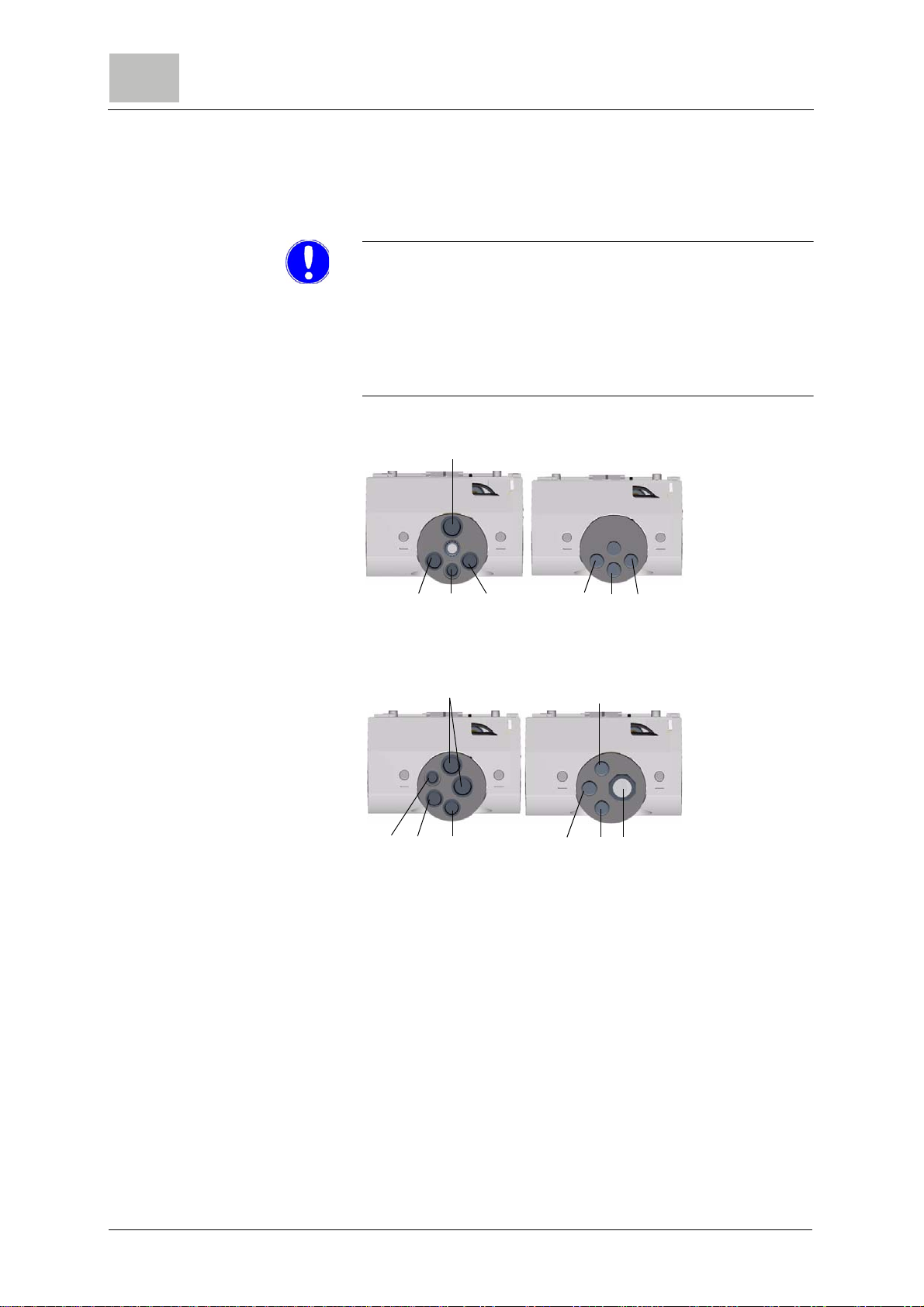
Arrangement of
the sensors
A Membrane sensor: FC1, CD7, OZ7, TC1, TC1-S
B Redox
C Fluoride or conductivity
DpH
1 Remove the protection caps from the sensors.
2 Install sensors (see figure above) in the cell body cover.
The sensors are marked as follows:
Membrane sensor for free chlorine, chlorine dioxide, ozone and
total chlorine (A)
mV:Sensor for Redox, marked "mV" (B)
pH:Sensor for pH value, marked "pH" (C)
µS:Sensor for conductivity, marked "LF325" (D)
A
D C B D C B
DEPOLOX®5 DEPOLOX®5
non-pressurised version pressurised version
C B D D B A
VariaSens non-pressurised VariaSens pressurised
version version
AC
This manual suits for next models
14
Table of contents
Other Evoqua Control Unit manuals


