Trumpf S 160 - 7 User manual

Operator's manual
english
S 160 - 7


E241en1_2.doc S 160 - 7 GB 1
Hand sheers S160-7 Fig. 10232
S 160-7 specifications
Max. material thickness:
•Steel up to 400 N/mm21.6 mm
•Steel up to 600 N/mm21.2 mm
•Steel up to 800 N/mm21.0 mm
•Aluminium 250 N/mm22.0 mm
Smallest radius for
curve-shaped cutouts 15 mm
Working speed 5-7 m/min
Nominal power consumption 520W
Number of strokes
under maximum load max. 3000/min
Weight 1.5kg
Operating pressure (flow pressure) 6 bar
Air consumption at 6 bar 0.4 m3/min
Required inner ∅
of compressed air tube 9 mm
(maximum output is not reached if ∅
is smaller)
Noise / Vibration
Measured values established in acc. with EN 50 144.
The A-weighted sound level of the unit is typically 73
dB (A). The noise level can exceed 85 dB (A) during
operation.
Wear ear protection!
The weighted acceleration is typically 2.60 m/s2.
Proper use
The TRUMPF hand sheers S160-7 are a pneumatic
hand machine
•used to part plate-shaped workpieces made of
material such as aluminium, plastic, etc.
•to cut straight or curved outer edges and inside
cutouts
•to cut along a scribed line
Safety instructions
The machine can only be operated safely if
you have read and understood both the
operating and safety instructions (red print)
and follow these instructions carefully.
The unit may only be used with a chip
deflector (hand protection).
Check the unit, compressed-air tube and reception
coupling before each use.
Have all damaged parts repaired by an expert.
Always wear safety glasses, ear
protection, protective gloves and
proper footwear when working with the
machine.
•Do not connect the compressed air unless the
machine is turned off.
•Always disconnect the compressed-air tube from
the machine before beginning any work on the
machine!
GB
9Ram
11 Top cutter and bottom
cutter
12 Fastening screw
14 Fastening screw
15 Adjusting screw
16 Fixed blade carrier
18 Chip deflector
(Hand guard)
324 Lever and On/off switch
331 Sleeve
9
12
11
11
14
15
16
18
324
331
2GB S 160 - 7 E241en1_2.doc
•Always guide the compressed-air tube back away
from the unit.
•Use only original TRUMPF accessories.
Before initial use
1. Read the chapter on safety
Safety instructions
2. Check whether the installed cutters are suitable
for the material that is to be machined. For
high-tensile sheets (> 400 N/mm²) special
cutters should be used!
Cutter selection
3. Turn or replace blunt cutters.
Cutters
4. Check whether the cutting clearance is suitable
for the sheet thickness that is to be machined.
Cutting clearance
5. The flow pressure of the compressed air must
be 6 bar at the point of extraction.
6. Oil lubrication must take place for the
compressed-air motor
Maintenance
Operating instructions
Check the tools for wear and the oil lubrication of the
compressed-air motor every hour.
Never work with blunt tools!
(the compressed-air motor may stop).
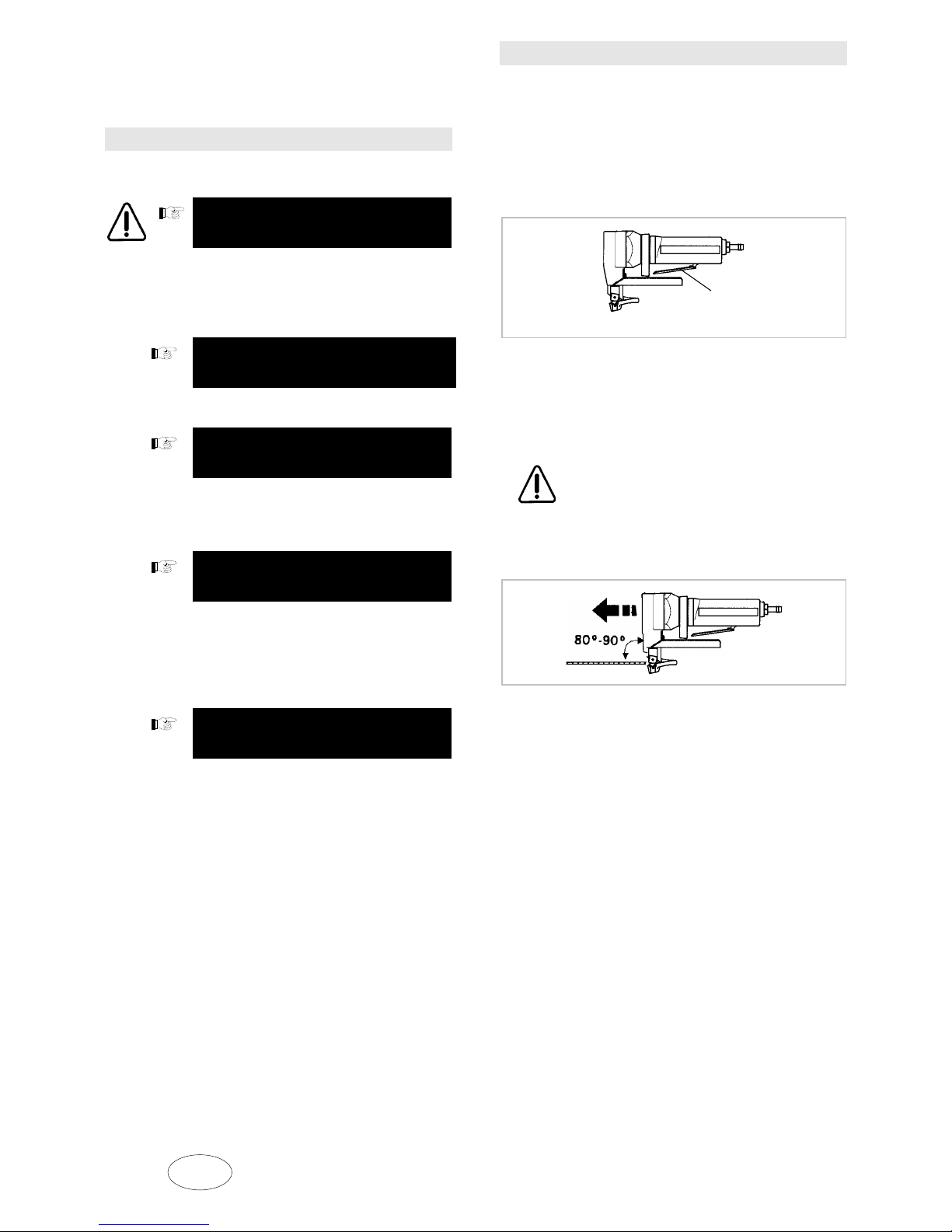
Turning the unit on and off
Fig. 10217
Turning on the unit: Press lever 1.
Turning off the unit: Release lever 1 (the lever
springs back into intial position and the flow of
compressed air is interrupted).
Do not begin machining the workpiece
until after the machine has been turned
on and has reached maximum speed!
Guide the unit towards the sheet surface at an angle
of 80° to 90° (figure).
Fig. 10263
Do not overload the unit and cause it to stop.
1
1 Lever

E241en1_2.doc S 160 - 7 GB 3
Excessive feed significantly reduces the service life
of the cutters and can damage the unit.
Sharp cutters always cut well and are easy on the
machine. Always turn or replace the cutters in good
time.
Cutting radii: Do not tilt the machine and work with
minimal feed.
Work upside down with the fixed blade carrier
pointing upward when cutting along the edge,
particularly during precision cutting along a scribed
line.
Cutter selection
Moving cutter blade (top cutter) and fixed cutter
blade (bottom cutter) have the same shape and are
mutually (top or bottom) interchangeable. All cutters
have 4 cutting edges. These are not regrindable
"fourfold-reverse blades". Two different cutter types
may be selected from the following table according
to the thickness, tensile strength and type of
workpiece that is to be machined:
M a t e r i a l
Cutter-Type Order No. - thickness
(mm)
- type,
- consistency
Standard * 126471 0.3 – 2.0 Aluminium
250 N/mm²
Standard * 126471 0.3 – 1.6 Structural steel
400 N/mm²
Cr ** 919760 0.3 – 1.2 Special steel
600 N/mm²
Cr ** 919760 0.3 – 1.0 Special steel
800 N/mm²
* The standard cutter for material consistencies up
to 400 N/ mm2 does not have a special type label.
** Cutter type "Cr" = chrome-steel cutter with
optimised cutter geometry, suitable for steels >
400 N/mm²
Risk of fracture!
It is urgently recommended that tools be used
according to the specifications found in the table.
Cutters
Disconnect the compressed-air tube from the
machine!
Top and bottom cutters are identical. They have 4
cutting edges each and can replace each other.
Turn the cutters 90° or replace them if cutting power
is insufficient.
To turn the cutters, loosen the screw on the
respective cutter; turn the cutter 90° and retighten
the screw.
Ensure that the adjusting screw (15) on the bottom
cutter fits closely.
Cutting clearance
Cutter clearance "a" is preset for a sheet thickness
of 1.0 mm when the machine is delivered. The
following values produce optimal cutting quality
when machining sheets that are thinner or thicker
than 1.0 mm:
Sheet thickness: Cutter clearance "a"
0.3 - 0.6 mm 0.10 mm
0.8 - 1.2 mm 0.25 mm (upon delivery)
1.3 - 1.6 mm 0.30 mm
Adjusting the cutting clearance
•Ensure that the moving cutter blade (top cutter) is
in lower dead centre position (by "tapping" on the
switch several times lightly).
•Disconnect the compressed-air tube from the
machine!
•Loosen lower cutter and move it to distance "a"
using the adjusting screw (15).
•Retighten cutters
•Screw down the adjusting screw (15) slightly.
•Check the distance using the setting gauge.
Warning! The cutters must not touch each other.
See Fig. 9917
4GB S 160 - 7 E241en1_2.doc
Fig. 9917
Maintenance
Always disconnect the compressed-air
tube from the machine before beginning
any work on the machine!
Cutter guide l u b r i c a t i o n
The cutter guide must only be lubricated after
repairs.
Original grease: Lubricating grease "S1" tube
TRUMPF order no. 121486
Gear/gear head l u b r i c a t i o n
Gear grease must be refilled or changed after
repairs but no later, however, than after 300 hours of
operation.
Original grease: Lubricating grease "G1"
TRUMPF order no. 139440
Alternative greases: BLASER Blasolube 308
BP Energrease HTB2
FUCHS Renoplex EP 1
MOBIL Mobiltemp SHC 32
Compressed-air motor l u b r i c a t i o n
Lubrication of the compressed-air motor
is very important. The motor will fail if it is
operated without lubrication even for a
short time.
Install oil lubricating device in the compressed-air
line (e.g. Atlas Copco DIM 25).
Checking the oil supply of the motor
Hold a piece of paper in front of the exhaust opening
in the motor housing while the machine is running.
The oil supply is sufficient if oil stains form.
Recommended oils (compressed-air motor
lubrication):
•BP Energol RD 80 (-15 to +10 C),
•BP Energol RD-E80 (+10 to 30°C),
•Shell Tellus Oil 15 (-15 to +10 C),
•Torculla 33 (+10 to +30 C).
Cleaning
Clean the filter 327 every 10 operating hours in order
to prevent throttling or power loss.
See the spare parts list for a diagram of filter
327.
Changing vanes
The performance of the machine decreases if the
vanes are excessively worn.
Vane replacement and all other repair work is to be
carried out by an expert!
Vane set (4) on the rotor of the compressed-
air motor. See Item 315 in the spare parts
list for corresponding diagram.
Repairs
Pneumatic tools comply with the relevant
safety regulations. Repairs may only be
carried out by qualified electricians in order to
prevent unnecessary accidents.
Use only original spare parts.
Please note the specifications on the output plate.
You will find a list of TRUMPF
representatives at the back of this operating
manual.
a
15
a Cutter distance 14 Fastening screw
9 Ram 11 Top and bottom cutter
15 Adjusting screw

E241en1_2.doc S 160 - 7 GB 5
Wearing parts
S160 Order no.
2 standard cutters
for processing constructional steel 126471
2 chrome-steel cutters
for processing high tensile sheets
(type plate "Cr") 919760
Note:
Moving cutter blade (top cutter) and fixed cutter
blade (bottom cutter) have the same shape and
are mutually (top or bottom) interchangeable.
All cutters have 4 cutting edges. These are not
regrindable "fourfold-reverse blades".
Original accessories
Accessories delivered with the machine
Description Order no.
Tool set
(top and bottom cutter, installed)
Sleeve 058378
(Item 331 in the spare parts list)
Allan key DIN 911-2 002946
Allan key DIN 911-3 067830
Operating manual 128636
Safety instructions (red print) 125699
Case 345243
Ordering spare parts and wearing
parts
Please proceeds as described below in order to
prevent delays and incorrect deliveries:
•Copy the page found opposite the replacement
part figure as "Order form for replacement parts
and wearing parts"
•Complete this form by stating
−the manufacturing No.
−the voltage, when ordering electrical
parts
−your exact address in the "Dispatch
address“ space
−the desired amount of parts in the
"Parts“ column
−the desired mode of dispatch (e.g. air
mail, special delivery, express, cargo,
parcel-post, etc.) in the line with the
symbol
•Should you wish to order wearing parts, write this
in the empty space at the end of the order form.
To differentiate between various tool types,
please observe the chapter "Wearing Parts."
•Send the completed form (per fax) to your
TRUMPF representative.
You will find a list of TRUMPF
representatives at the back of this operating
manual.
Notes on documentation
The document was written by the Technical
Documentation department of TRUMPF
Werkzeugmaschinen GmbH + Co.
All rights reserved, particularly those concerning the
duplication, distribution and translation of this
documentation, even in the event of property right
registration.
TRUMPF Werkzeugmaschinen GmbH + Co.

6GB S 160 - 7 E241en1_2.doc
Table of contents
Other Trumpf Trimmer manuals


