5
TT
TT
TABLE OF CONTENTSABLE OF CONTENTS
ABLE OF CONTENTSABLE OF CONTENTS
ABLE OF CONTENTS
SAFETY PRECAUTIONSSAFETY PRECAUTIONS
SAFETY PRECAUTIONSSAFETY PRECAUTIONS
SAFETY PRECAUTIONS ........................
........................
............ 2 – 32 – 3
2 – 32 – 3
2 – 3
IMPORIMPOR
IMPORIMPOR
IMPORTT
TT
TANT SAFETY INSTRUCTIONSANT SAFETY INSTRUCTIONS
ANT SAFETY INSTRUCTIONSANT SAFETY INSTRUCTIONS
ANT SAFETY INSTRUCTIONS
...................................................... 4...................................................... 4
...................................................... 4...................................................... 4
...................................................... 4
DISC FORMADISC FORMA
DISC FORMADISC FORMA
DISC FORMATSTS
TSTS
TS ........................................................
........................................................
............................ 66
66
6
REMOTE CONTROLREMOTE CONTROL
REMOTE CONTROLREMOTE CONTROL
REMOTE CONTROL ..........................................
..........................................
..................... 77
77
7
ACCESSORIESACCESSORIES
ACCESSORIESACCESSORIES
ACCESSORIES ..........................................................
..........................................................
............................. 77
77
7
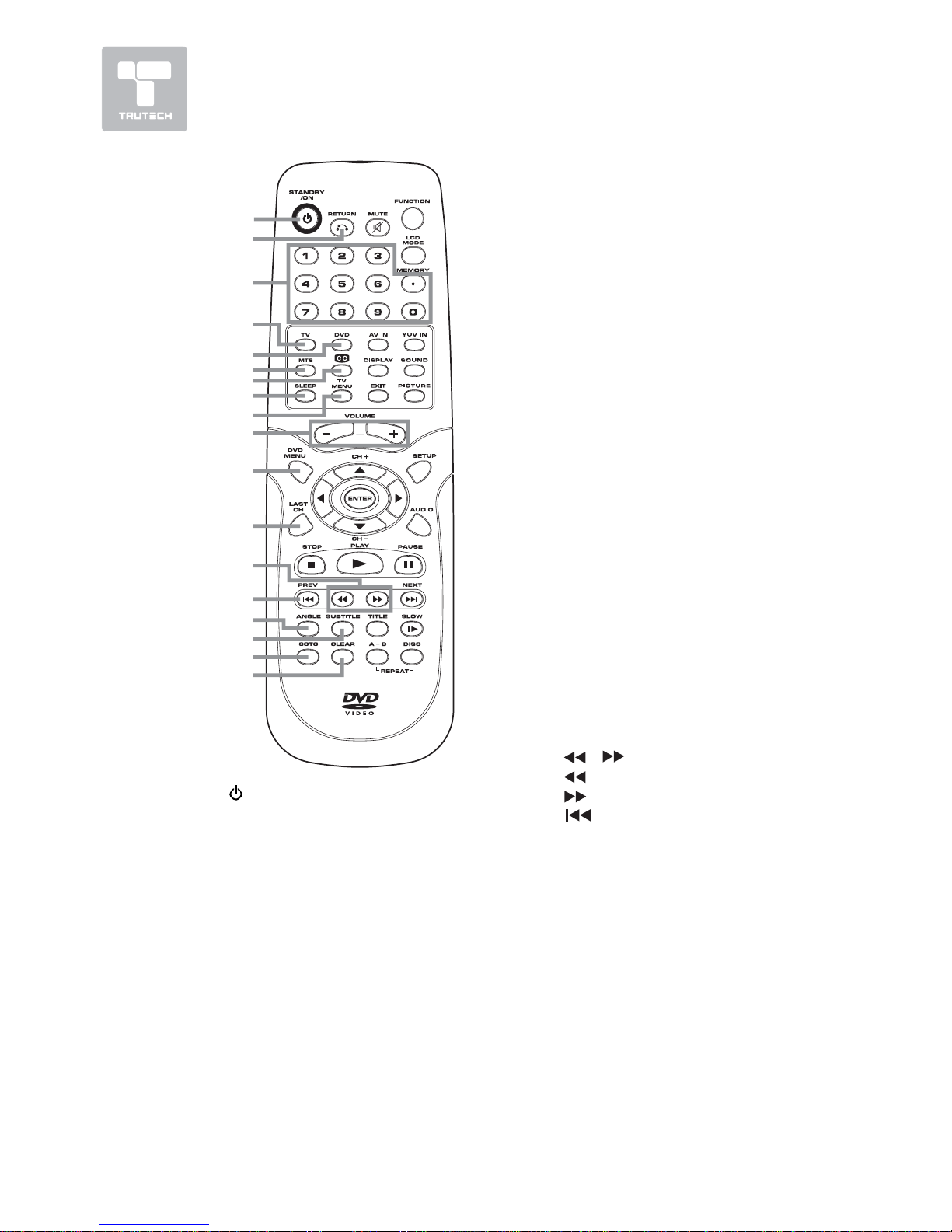
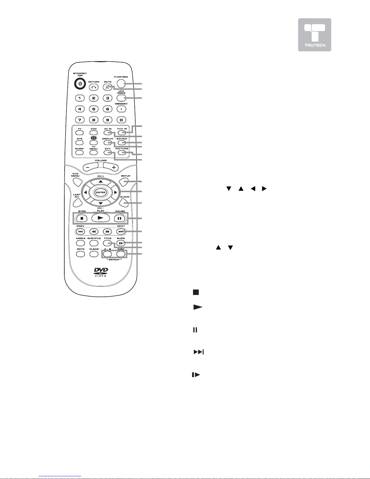
REMOTE CONTROL REFERENCE GUIDEREMOTE CONTROL REFERENCE GUIDE
REMOTE CONTROL REFERENCE GUIDEREMOTE CONTROL REFERENCE GUIDE
REMOTE CONTROL REFERENCE GUIDE
............................................... 8 – 9............................................... 8 – 9
............................................... 8 – 9............................................... 8 – 9
............................................... 8 – 9
UNIT REFERENCE GUIDEUNIT REFERENCE GUIDE
UNIT REFERENCE GUIDEUNIT REFERENCE GUIDE
UNIT REFERENCE GUIDE .....
.....
..........
..... 10 – 1110 – 11
10 – 1110 – 11
10 – 11
CONNECTIONSCONNECTIONS
CONNECTIONSCONNECTIONS
CONNECTIONS ......................................
......................................
................... 12 – 1712 – 17
12 – 1712 – 17
12 – 17
Connecting a TV Antenna/Cable/
Satellite ................................. 12
Connecting an A/V Device (VCR,
PVR Camcorder, Game System,
etc.) ............................... 13 – 15
Connecting a Hhigh-Definition (HD)
Source .................................. 16
Connecting a PC ...................... 16
Connecting an Audio Amplifier ........ 17
Connecting the AC Power Cord ...... 17
INSTINST
INSTINST
INSTALLAALLA
ALLAALLA
ALLATIONTION
TIONTION
TION ......................................................
......................................................
........................... 1818
1818
18
Removing the Base Stand ......... 18
Mounting on the Wall ............... 18
USING HEADPHONES .................. 19USING HEADPHONES .................. 19
USING HEADPHONES .................. 19USING HEADPHONES .................. 19
USING HEADPHONES .................. 19
UNIT OPERAUNIT OPERA
UNIT OPERAUNIT OPERA
UNIT OPERATIONTION
TIONTION
TION ..............................................
..............................................
....................... 1919
1919
19
Turning the Unit on .................. 19
Turning the Unit on for the First
Time ...................................... 19
SOUND SYSTEMSOUND SYSTEM
SOUND SYSTEMSOUND SYSTEM
SOUND SYSTEM ..............................................
..............................................
....................... 1919
1919
19
CD/DVD OPERACD/DVD OPERA
CD/DVD OPERACD/DVD OPERA
CD/DVD OPERATIONTION
TIONTION
TION ......................
......................
........... 20 – 2120 – 21
20 – 2120 – 21
20 – 21
Playing a Disc ......................... 20
Pausing Playback (Still Mode) ...... 20
Stopping Playback .................... 20
Skip (Forward/Reverse) ............ 20
Fast Forward/Fast Reverse ...... 20
Slow-motion Play (DVD) ............. 20
Audio Selection (DVD) .............. 21
Subtitle Selection (DVD) ........... 21
Angle Selection (DVD) .............. 21
SPECIAL FUNCTIONSSPECIAL FUNCTIONS
SPECIAL FUNCTIONSSPECIAL FUNCTIONS
SPECIAL FUNCTIONS ....................................
....................................
.................. 2222
2222
22
Display Function (DVD) ............. 22
Locating a Specific Title (DVD) ....... 22
Locating a Specific Chapter/Track
................................................ 22
Locating a Specific Time ........... 22
CD/DVD PROGRAMMABLE MEMORYCD/DVD PROGRAMMABLE MEMORY
CD/DVD PROGRAMMABLE MEMORYCD/DVD PROGRAMMABLE MEMORY
CD/DVD PROGRAMMABLE MEMORY
.................................................. 23.................................................. 23
.................................................. 23.................................................. 23
.................................................. 23
Programmable Memory ............. 23
Title/Chapter Programmed Playback
(DVD) .................................... 23
Track Programmed Playback (CD)
............................................ 23
REPEAREPEA
REPEAREPEA
REPEAT PLAT PLA
T PLAT PLA
T PLAYBACKYBACK
YBACKYBACK
YBACK ..........................
..........................
............. 23 – 2423 – 24
23 – 2423 – 24
23 – 24
Repeating a Phapter/Title (DVD)
................................................ 23
Repeating a Single Track/Whole CD
(CD) ...................................... 23
. Repeating a Specific Section (DVD)
(CD) ...................................... 24
PLAPLA
PLAPLA
PLAYING A PICTURE FILE DISCYING A PICTURE FILE DISC
YING A PICTURE FILE DISCYING A PICTURE FILE DISC
YING A PICTURE FILE DISC ............
............
...... 2424
2424
24
CUSTOMIZING THE DVD FUNCTIONCUSTOMIZING THE DVD FUNCTION
CUSTOMIZING THE DVD FUNCTIONCUSTOMIZING THE DVD FUNCTION
CUSTOMIZING THE DVD FUNCTION
SETTINGSSETTINGS
SETTINGSSETTINGS
SETTINGS ................................................................
................................................................
................................ 2525
2525
25
Language Setup ...................... 25
Video Setup ............................ 25
System Setup ......................... 25
TV Type .................................. 25
Default .................................. 25
TV SETUP ............................. 26 – 31TV SETUP ............................. 26 – 31
TV SETUP ............................. 26 – 31TV SETUP ............................. 26 – 31
TV SETUP ............................. 26 – 31
Video Menu ............................ 26
VGA Settings in PC Mode ......... 27
Audio Menu ............................ 27
TV Menu ................................ 28
Skip Channel Setting ................ 28
Setup Menu ...................... 28 - 30
Time Setup Setting .................. 29
Caption Setting ....................... 30
Restore Setting .......................... 30
Parental Menu .................... 30 – 31
Password ............................... 30
Parental Control Setting ........... 31
LANGUAGE CODE LIST ................. 32LANGUAGE CODE LIST ................. 32
LANGUAGE CODE LIST ................. 32LANGUAGE CODE LIST ................. 32
LANGUAGE CODE LIST ................. 32
MAINTENANCE ........................... 33MAINTENANCE ........................... 33
MAINTENANCE ........................... 33MAINTENANCE ........................... 33
MAINTENANCE ........................... 33
TROUBLE SHOOTING GUIDETROUBLE SHOOTING GUIDE
TROUBLE SHOOTING GUIDETROUBLE SHOOTING GUIDE
TROUBLE SHOOTING GUIDE ........................
........................
............
..............................................................................
.......................................
.......................................
....................................... 34 – 3534 – 35
34 – 3534 – 35
34 – 35