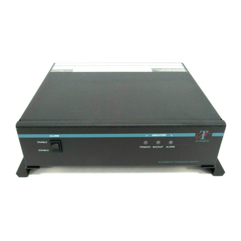
TSi Power ATS-800 Series User guide

TSI Power Corporation April, 2021 SG03502
ATS-800 Series Rev. 3
Page 1of 5
START-UP GUIDE
TSI Power Mo el Number: ATS-800 Series
DANGER:
Make sure unit is de-energized bef re beginning.
CAUTION:
These instructi ns must be f ll wed r b ard failure will result.
Caution: No user serviceable parts.
Caution: Only a traine engineer, electrician or technician shoul perform this proce ure.
Caution: For personnel safety, remove metallic watches an rings.
Always wear protective eye glasses, insulate gloves an insulate shoes.
This is a quick reference start-up gui e. Go to TSI Power's website or contact TSI irectly to obtain the ATS-800 Series
Pro uct Manual. (TSI Power's contact information is on page 5.)
IMPORTANT SAFETY INSTRUCTIONS: SAVE THESE INSTRUCTIONS – This manual contains important
instructions for the ATS-800 Series that shoul be followe uring installation an maintenance of the ATS.
Please inspect the unit for visible shipping amage (such as amage case or broken parts)
Table f C ntents Page
Safety Alerts....................................................................................................................................................................... 2
Tools an Test Equipment Require ................................................................................................................ 2
Voltage Selection......................……………………………………………………………………...................................................... 2
Remote Status / Alarm Monitoring..…………………………………………………….……….…...................................... 3
Power-Up Proce ure……………………………….…………………………………….…………..................................................... 4
Contact Information...…………………………………………………………………………………................................................... 5

TSI Power Corporation April, 2021 SG03502
ATS-800 Series Rev. 3
Page 2of 5
SAFETY ALERTS - SAFETY SIGNAL WORD DEFINITIONS
This ocument contains safety alert pictorial Symbols an Wor s that point out areas an proce ures that require
special attention with regar s to safety. These Symbols an Wor s are efine in ANSI Z535.4-1998, Pro uct Safety
Signs an Labels.
DANGER:
DANGER indicates an imminently hazard us situati n which, if n t av ided, will result in death r seri us injury.
WARNING:
WARNING indicates a p tentially hazard us situati n which, if n t av ided, will result in death r seri us injury.
CAUTION:
CAUTION indicates an imminently hazard us situati n which, if n t av ided, may result in min r r m derate injury.
It may als be used t alert against unsafe practices.
The safety alert pictorial symbol appears in this ocument to make users aware of important operating an
safety concerns.
T ls and Test Equipment Required
•Miscellaneous han tools
•DMM ( igital voltmeter)
V ltage Selecti n
1. If you have a 208, 220 or 240 V ATS the voltage range can be change . The factory setting is either set to HIGH
(220 to 240 V) or LOW (208 V) epen ing on ATS mo el or ere . If the factory preset is not esire , performing
the following steps will change the voltage transfer points.
2. Make sure both Primary an Backup AC sources to the ATS are e-energize .
3. Remove the ATS case cover.
4. Locate the jumper at JP1 (HIGH) or JP2 (LOW). See figure 1.
5. To change the voltage selection simply move the Jumper from the JP1 (HIGH) to JP2 (LOW) position or JP2 (LOW)
to JP1 (HIGH) position ( epen ing on the factory preset of your ATS).
6. Replace the ATS case cover.
Rem te Status / Alarm M nit ring
1. A DB-9 female connector in the rear of the unit provi es status / alarm signals for remote monitoring of the sta-
tus of the ATS.
2. Primary AC Input Status DB-9 Pins are: _5_NO _1_NC_2_COM
3. Backup AC Input Status DB-9 Pins are: _6_NO_3_NC_4_COM
4. When Primary AC Input is present an IN SPECIFICATION, there is an OPEN circuit between pin_5_an pin_2_.
When Primary AC input is OUT OF SPECIFICATION, there is a CLOSED circuit between pin_5_an pin_2_.
5. When Backup AC Input is present an IN SPECIFICATION, there is an OPEN circuit between pin_6_an pin _4_.
When Backup AC input is OUT OF SPECIFICATION, there is a CLOSED circuit between pin_6_ an pin_4_.
6. Maximum voltage an current that can be use for monitoring the status an alarm of the ATS Series is 120 VDC
(VAC), 1 A (maximum DB-9 connector rating).

TSI Power Corporation April, 2021 SG03502
ATS-800 Series Rev. 3
Page 3of 5
CAUTION: The unit must be placed in a well – ventilated area t prevent risk f fire due t ver-
heating. Ventilati n sl ts must n t be bstructed.
WARNING: The ATS-800 is n t rdinarily intended f r use in a stacked c nfigurati n with ther
ATS-800 units, th ugh this can be d ne with care. In the event a stacked installati n is planned,
please c ntact TSI P wer f r assistance.
CAUTION: The ATS must be pr tected by an upstream branch circuit pr tect r, f r b th the Pri-
mary and the Backup, at 125% f the ATS current rating (the maximum input current rating as sh wn
n the ATS pr duct label) per the Nati nal Electric C de r per l cal electrical c des if utside f the
United States.
JP13 (ATS ENABLE)
(F
igure 1)
PZ00120
-
5 Control Boar
JP
1 (HIGH) or JP2 (LOW)
PZ00127
-
5 Control Boar

TSI Power Corporation April, 2021 SG03502
ATS-800 Series Rev. 3
Page 4of 5
P wer-Up Pr cedure
1. Perform a visual inspection of the ATS-800 unit an verify that it is not physically amage . Verify that the
equipment label states correct voltage, frequency an amperage of the input & output AC power sources.
Also, verify that the state output voltage, frequency an amperage are compliant with the input power
requirement of the loa equipment to be powere by ATS-800.
CAUTION: Turn b th switches marked as Primary Input Breaker and Backup Input breaker t OFF
p siti n.
WARNING: Make sure that b th Primary and Backup AC input wires are de-energized.
2. Connect (or plug in) both the Primary an Backup AC input connections. For 15, 20 an 30 Amp har wire
units recommen e tightening torque is 0.79Nm (7 in.-lbs), for 40 Amp har wire units recommen e
tightening torque is 2.26Nm (20 in.-lbs).
CAUTION: Make sure that b th Primary and Backup AC input v ltages and frequencies match
th se specified n the pr duct label affixed t the ATS unit. The ATS will nly perate when the input
v ltage is within specificati n and when the input frequency is within ± 5 % f that specified. B th
primary and backup must be the same n minal frequency.
3. Turn on the Backup AC circuit breaker in the rear of the ATS unit. Make sure that the au ible alarm switch
(in front of the ATS unit) is in the "ENABLE" position.
4. The yellow LED shoul turn on an the alarm soun must turn ON (re alarm LED must turn ON; green
LED must be OFF).
5. Turn on the Primary AC circuit breaker in the rear of the ATS unit.
6. The green LED must turn on after several secon s. Yellow LED must turn OFF. The au ible alarm (soun )
an re alarm LED must turn OFF.
7. Turn off the Primary AC circuit breaker. The green LED must turn off. The yellow Backup LED must turn ON.
Re alarm LED an alarm (soun ) must turn ON.
8. Turn on the Primary AC circuit breaker. After several secon s, ATS must return to normal operating
con ition as in step 6.
9. Turn off the Backup AC circuit breaker. The green LED must remain ON an the re alarm LED an alarm
soun must turn on.
10. Turn on the Backup AC circuit breaker. After several secon s, ATS must return to normal operating
con ition as in step 6.
TESTING WITH ACTUAL LOAD EQUIPMENT (SUCH AS COMPUTERS, PLC, TELECOM EQUIPMENT, ETC.)
CAUTION: T av id electric sh ck r accidents, ensure that b th Primary & Backup AC s urces are
de-energized bef re making the wire c nnecti n t the AC s urces.
11. If the above test steps (1) through (10) are performe an the ATS is functioning properly, then actual loa
equipment can be connecte (or plugge into) the output terminal block (or output socket) of the ATS. For
15, 20 an 30 Amp har wire units recommen e tightening torque is 0.79Nm (7 in.-lbs), for 40 Amp
har wire units recommen e tightening torque is 2.26Nm (20 in.-lbs).
12. Perform steps 3 through 10 assuring that the loa is operating properly.
13. En

TSI Power Corporation April, 2021 SG03502
ATS-800 Series Rev. 3
Page 5of 5
Shoul you have any questions or encounter problems uring the power up proce ure,
contact TSI Power's technical support staff imme iately.
USA or Cana a (toll-free): 800-874-3160
International customers: +1-715-623-0636
E-mail: sales@tsipower.com
Factory a ress: 1103 West Pierce Avenue, Antigo, Wisconsin 54409, USA
Internet: www.tsipower.com
Hours of operation are from 8AM to 5PM (Central Stan ar Time), Mon ay through Fri ay
TSI Power will try to reply to E-mail requests for technical support within 24 hours.
REVISIONS
Rev.
DATE
REASON FOR REVISION
0
March, 2018
Initial release
1
April
,
201
8
A e
stac
king infor
mation, page
4
.
2
September, 2019
Remove
r
emote
e
nable
function
section
, page 2
.
3
April
, 2021
New TSI
logo an
font
. Remove Fax
information.
Other manuals for ATS-800 Series
1
Table of contents
Other TSi Power Switch manuals
Popular Switch manuals by other brands

Omron
Omron D5C Series manual

D-Link
D-Link DES-3028 user manual

ABB
ABB 3299-11500 Instructions for installation and use

Rose electronics
Rose electronics QuadraVista Installation and operation manual

CAMBRIONIX
CAMBRIONIX PowerPad15s user manual

Cisco
Cisco Cisco mds 9216 - fabric switch Hardware installation guide