TSL USP3 Series User manual

WWW.TSLPRODUCTS.COM
USP3
User Manual

USP3 User Manual Page 2of 73
Table of Contents
Table of Contents...............................................................................................2
Overview............................................................................................................4
Installation.........................................................................................................7
System Configuration.........................................................................................8
View Received Data .........................................................................................10
Web Keys.........................................................................................................11
GPI Events........................................................................................................13
GPO Actions.....................................................................................................15
Remote Device Assignment .............................................................................19
Keymapper ......................................................................................................22
GTP-32 / DC20 Receive Events.........................................................................24
Serial Port Configuration..................................................................................26
AHSC TX Actions...............................................................................................28
AHSC RX Events................................................................................................30
HTTP GET / POST Actions .................................................................................33
SNMP TX/RX Actions........................................................................................35
MEM Configuration .........................................................................................38
Conditional Logic .............................................................................................40
Count Up Down Timer .....................................................................................42
Event Action Table ...........................................................................................44
Tally Assignment..............................................................................................51
Redundant Mode.............................................................................................57
Examples: Receive Pattern Matching...............................................................62
Examples Sequences........................................................................................65
Examples: MEM Flip Flop.................................................................................66
Examples: MEM Radio Group ..........................................................................67
Examples: GPO Momentary Radio Group ........................................................68

USP3 User Manual Page 3of 73
Panel Layout ....................................................................................................69
Specifications...................................................................................................70
Warranty..........................................................................................................73

USP3 User Manual Page 4of 73
Overview
When you need to push a button, but it doesn’t have
any!
Tactile –Fast –Easy –Dependable CONTROL
The Universal Switch Panel (USP3) makes it easy to add tactile push buttons where and
when you need them:
✓8 and 16 Push Buttons
✓Tabletop & Rackmount
✓RS232/RS422 serial port
✓Fast Ethernet (100 BASE-T Full Duplex)
Use the USP3 when you need to:
•Control a GPI Output and status a GPI Input
•Transmit Ethernet TCP / UDP/ SNMP / HTTP messages and status responses.
•Receive Serial or Ethernet data to turn on/off a GPI Output.
•Transmit Serial messages and status responses. Receive specific Serial data
and then transmit an Ethernet or SNMP notification
•Trigger a simple or complex sequence of actions from a Keypress or Source
event: GPI Outputs, Serial & Ethernet messages
•Periodically send a heartbeat message: “I’m alive!”
•Use a Watchdog timer to transmit an SNMP notification after
a time period of no heartbeats.
•Monitor SNMP Traps and turn on GPI Outputs (GPO)
•Control Flex Control Network devices, Tally them and more...
The Universal Switch Panel (USP3) is a panel of generic switches designed to emulate the
operation of mechanical switches. The mechanical switch feel is provided by the USP3’s
front panel switch. The mechanical switch’s contact closure is provided by the USP3’s
general purpose outputs (GPO). The mechanical switch’s internal tally indicator is provided
by the USP3 switch’s backlight.

USP3 User Manual Page 5of 73
Unlike mechanical switches, the operating mode of the front panel switches, GPO contact
closures, and tally can be easily configured by the user for their specific application.
Additionally, a switch on the Universal Switch Panel (USP3) can be configured to control
Actions on another USP, GTP, IP Buddy or AIB as well as tally sources off remote USP’s,
GTP’s, IP Buddy’s or AIB’s.
GETTING STARTED….
1. Go to Installation Section to install the USP3.
2. Go to System Configuration Section to set static IP address, Subnet Mask, and
Gateway address.
3. Go to Remote Device Assignment Section to enter IP addresses for remote devices
that USP3 will communicate with.
4. Go to System Configuration section to set default settings.

USP3 User Manual Page 6of 73
EQUIPMENT LIST
Qty
Component
Part Number
1
USP3 Switch Panel
USP3-8, USP3-8D, USP3-16
1
USP3 Power Supply
Included
1
USP3 Power Cord
Included
4
DB37 Cables
Included based on Kit
4
DB25 Cables
Included based on Kit
VERSION HISTORY
Issue
Date
Change Details
1
03/21/20
First Issue

USP3 User Manual Page 7of 73
Installation
1. Connect supplied power supply to POWER 1 connector. For redundant power option,
connect power supplies to POWER 1 and POWER 2 connectors.
2. Connect Ethernet cable to ETHERNET connector.
DEFAULT ETHERNET CONFIGURATION
IP Address: 192.168.10.217
Subnet Mask: 255.255.255.0
Gateway: 192.168.10.1
The USP3 is configured using a standard web browser (Safari, Firefox, and Chrome). Enter
the USP3’s IP address in the Address/ URL bar, typically located at the top of the web
browser page, to access the Home Page. Use the links on the left side of the Home Page to
access the desired configuration web pages.
All configuration settings are saved in non-volatile memory in the USP3. Settings are
retained when power is removed.
Settings may be uploaded to a computer as a configuration file (.dnf) for storage.
Configuration files may be downloaded from a computer into the USP3 to restore a saved
configuration. A configuration file contains all of the USP3’s configurations except IP
address, subnet mask, and gateway address. The USP3 does not support partial
configuration upload or download. The configuration file is a not a text formatted file. It
cannot be viewed or modified with a text editor.
To access the System Configuration web page, use the following log-on when prompted:
USERNAME: dnfuser
PASSWORD: controls

USP3 User Manual Page 8of 73
System Configuration
The System Configuration page is used to configure the network settings for the USP3.
Additionally, this page is used to install firmware upgrades, SAVE/RESTORE configuration
files, set NTP time, manage/view logs and set factory defaults for the USP3-TSA panel:
The default IP address is: 192.168.10.217
The default Gateway is: 192.168.10.1
The default Subnet Mask is: 255.255.255.0

USP3 User Manual Page 9of 73
PARAMETER
DESCRIPTION
P1 Software Upgrade:
Use this link to install the P1 upgrade file provided by DNF Controls
Web Upgrade:
Use this link to install the Web pages upgrade file provided by DNF
Controls
Save Configuration
to PC:
Use this link to save the USP3’s current configuration to a
configuration file on
a computer. The web browser will prompt for
file name and directory. The file
extension must be ‘dnf’.
Restore Configuration
from PC:
Use this link to download a configuration file from your computer
to the USP3.
The web browser will prompt for directory and
configuration file name. The file
extension must be ‘dnf’.
Set Factory Defaults:
Use this link to reset all USP3 configuration settings to factory
defaults. This
will NOT change the IP address, subnet mask or
gateway address. The USP3
will automatically reboot.
Redundant Mode
on Powerup:
Use this dropdown to set the Redundant Mode on Powerup. If set
to “Enabled” the USP will boot up with redundant mode enabled
upon powerup. If set to “Disabled” the USP will boot up with
redundant mode disabled upon powerup.
Key Mode
on Powerup:
Use this dropdown to set the Key Mode on Powerup. If set to
“Enabled” the USP will boot up with its keys enabled upon
powerup. If set to “Disabled” the USP will boot up with its keys
disabled upon powerup.
Enter Label:
Enter label to be displayed on top right of all web pages
Log received data from:
Use this dropdown to set the remote device that the USP will log
received data from. After the remote device has been selected,
select the “View Received Data” to enter the log page (See below).
Enter the new IP settings
below:
DHCP ENABLED/DISABLED: Use this dropdown to enable or disable
DHCP.
Enter the new IP address, Gateway, Subnet Mask Primary DNS and
Secondary DNS. Click on Save Config to
save the new entries. The
USP3 will automatically reboot.
USP3 User Manual Page 10 of 73
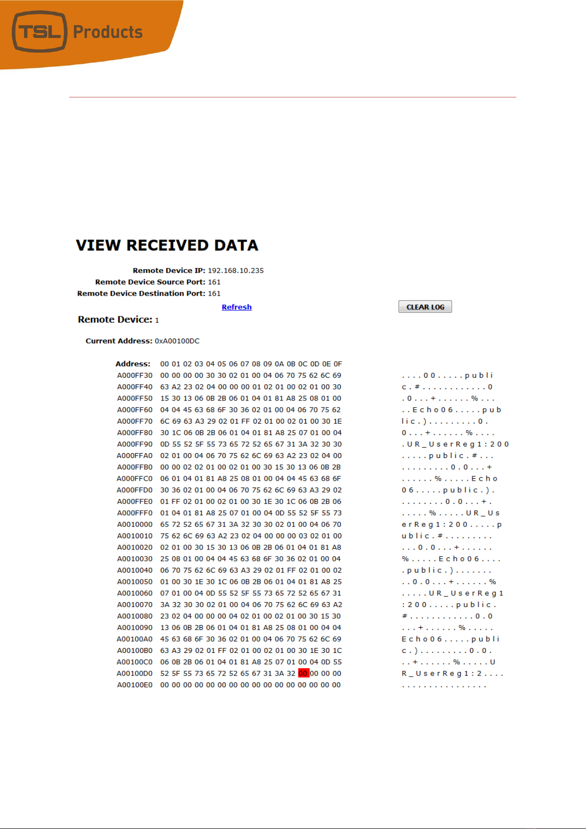
View Received Data
The USP3 View Received Data link under the System Maintenance page monitors all
incoming data from the selected remote device. Use the Refresh link to view incoming
data as it is received. Use the Clear Log link to clear the log data.
!!NOTE!! View Received Data page does not auto-refresh and does not generate a log
file.

USP3 User Manual Page 11 of 73
Web Keys
“USP3 Web Keys” when operators cannot physically press the USP3 buttons.
USP3 Web Keys are virtual buttons, on the USP3 Home web page, designed to emulate the
operation of the USP3’s mechanical switches. Each Web key tallies the same Tally Source as
its physical key without requiring any change to the USP3 configuration. Click on the web
key to “press” the button and provide the same Momentary control function as the physical
switch.
There is one Web Key displayed for each physical key. Both USP3 Web Keys and the USP3
hardware front panel can be used for control and tally simultaneously.
WEB KEY INSTALLATION
The Web Keys are fully operational, controlling and tallying the same as the physical keys by
default in the current software. If Web Key or Web Key settings are not visible, please reach
out to TSL support for a software update. Go to the System Configuration web page to
configure when they are visible.

USP3 User Manual Page 12 of 73
SYSTEM CONFIGURATION PAGE
1. Navigate to the SYSTEM CONFIGURATION page and locate the dropdown shown
below.
Display Web Keys without login –The Web Keys are visible without requiring login
to the USP3.
Display Web Keys only when logged in –The Web Keys are visible only after
successful login. After logging out, the Web Keys are no longer visible.
Do not display Web Keys –The Web keys are not visible at any time.
2. Select the desired mode from the dropdown that best suites your requirements and
click on “Save Mode” to save your changes. No reboot is required for the changes to
take effect.

USP3 User Manual Page 13 of 73
GPI Events
Use this page to configure the operation of the GPIs. If the GPIs are not used, this page
may be left blank.

USP3 User Manual Page 14 of 73
PARAMETER
DESCRIPTION
GPI Label:
Enter any 15 characters or symbols. For convenience only.
Used in Event Action
Table
User Defined
ON State:
OPTO ON: The GPI is ON when the opto-isolator is energized (powered).
The GPI is OFF when the opto-isolator is de-energized.
OPTO OFF: The GPI is ON when the opto-isolator is de-energized.
The GPI is OFF when the opto-isolator is energized (powered).
User Defined
ON
Mode:
LATCHED:
The GPI turns ON and stays ON.
The GPI turns OFF and stays OFF.
MOMENTARY:
The GPI turns ON for a short time and then turns OFF and stays OFF.
This pattern repeats every time the GPI becomes active
Debounce
Time:
The time period that the GPI must remain ON to be detected as ON. The selected
time is multiplied by 10 milliseconds to compute the actual Debounce time.
Currently:
Current state of GPI as defined by User Defined ON State.
GPI Configuration
1. Click on the GPI EVENTS tab. The GPI Configuration page will be displayed. The USP3-
16 will display 16 GPIs. The USP3-8 will display 8 GPIs.
2. Click on the drop-down arrow in each column to view the list of available options/
values. Select the desired option/ value by clicking on it.
3. Click in the User Defined ON State column and select the ON state for the GPI.
4. Click in the User Defined ON Mode column and select the operating mode for the GPI.
5. Click in the Debounce column and select the debounce time for this GPI. (The
selected time is multiplied by 10 milliseconds to compute the actual Debounce time.)
Debounce time is the time period that the GPI must remain on to be detected as ON.
6. Repeat steps 3 - 5 to configure each GPI.
7. Click on the Save button to save changes. Changes will take effect immediately after
saving.
OR,
Click on any other page button to exit without saving changes.

USP3 User Manual Page 15 of 73
GPO Actions
Use this page to configure the operation of the local GPOs. If the GPOs are not used, this
page may be left blank.

USP3 User Manual Page 16 of 73
GPO OPERATING MODE
Each GPO can be configured by the user to operate according to one of the following
operating modes. Only one operating mode can be assigned to a GPO at any time. The
assignment of a new operating mode automatically overrides the previous operating mode
assignment. All GPO configurations are done from the USP’s GPO page or the USP’s Event
Action Table.
A) MOMENTARY OPERATION
When the controlling switch is pressed, the GPO will immediately turn on and start its
ON Time timer. When the user configured time period has elapsed, the GPO will
automatically turn OFF regardless of the state of the controlling switch. If the
controlling switch is held pressed after the elapsed time or quickly released before the
elapse time has expired, the GPO will only turn OFF when the user configured ON Time
has elapsed. The controlling switch must be released and then re-pressed before the
GPO will turn ON again.
B) FOLLOW/ LATCH OPERATION
When the controlling switch is pressed, the GPO will immediately turn ON. When the
controlling switch is released, the GPO will immediately turn OFF. If the controlling
switch is held pressed, the GPO will stay ON while the switch is being held. This
operation is configured via the USP’s Event Actions table.
C) TOGGLE OPERATION
When the controlling switch is pressed, the GPO will immediately change state. If the
GPO was ON, it will turn OFF. If the GPO was OFF, it will turn ON. The GPO will not
change state when the controlling switch is released. When the switch is released, the
GPO will remain in its last state. This operation is configured via the USP’s Event Actions
table.
D) FLIP FLOP MODE OF OPERATION
One switch controls two GPOs. When the switch is pressed and the current status is
ON, then the 2nd GPO will be turned ON and the 1st GPO will be turned OFF. When
the switch is pressed and the current status is OFF, then the 1st GPO will be turned ON
and the 2nd GPO will be turned OFF.
The GPOs can be configured as LATCH or MOMENTARY. The FLIP FLOP operation will be
configured on a GPO by GPO basis in the Event Action Table. The FLIP FLOP operation is
defined for GPOs located in the same unit, however it can be used for GPOs across
multiple USP units. This operation is configured via the USP’s Event Actions table (See
page 12).

USP3 User Manual Page 17 of 73
E) GROUP (RADIO GROUP) OPERATION
The GPO Group operates like a radio group of interlocked switches. Pressing one switch
causes the other switches to automatically release. Only one switch will remain pressed
at any time.
A GPO can belong to one and only one GPO Group. More than one GPO Group can exist
with each group made up of other GPOs. When a GPO is assigned to a new GPO Group,
it is automatically removed from its previous group.
Only one member of a GPO Group can be ON at any time. When a GPO member is
turned ON, all of the other members are immediately turned off. The GPO will stay on
until another member of the group is turned on. With the exception of powering on the
USP, at least one GPO from the GPO group will be turned on.
F) GPO CONTROL BY SWITCH ON A REMOTE USP
The GPO can be controlled by a switch on a remote Universal Switch Panel in addition
to being controlled by a switch on the same panel. The GPO will operate according to
its user configured Operating Mode whenever the local or remote switch is pressed and
released.
G) GPO CONTROL BY GTP-32 OR DC20 EVENT
The GPO can be controlled by a GTP-32 or DC20 event― GPI or Combinatorial. It will
operate according to its user configured Operating Mode as if a local switch had been
pressed or released.
H) GPO CONTROL BY ETHERNET EVENT
The GPO can be controlled by an incoming Ethernet command string/event. It will
operate according to its user configured Operating Mode as if a local switch had been
pressed or released.
PARAMETER
DESCRIPTION
GPO Label:
Enter any 15 characters or symbols. For convenience only, used in Event
Action Table.
User Defined
ON State:
RELAY OPEN: The relay is OPEN when the GPO is ON.
The relay is CLOSED when the GPO is OFF.
RELAY CLOSED: The relay is CLOSED when the GPO is ON.
The relay is OPEN when the GPO is OFF (Factory Default).
User Defined
Operating
Mode:
MOMENTARY: The GPO turns ON, waits for the MOMENTARY ON TIME to
expire, and then
automatically turns OFF.
LATCH: The GPO turns ON and stays ON.
The GPO turns OFF and
stays OFF.

USP3 User Manual Page 18 of 73
Momentary
ON
Time:
For MOMENTARY operating mode only. ON duration for Momentary GPO.
Drop down menu
settable from 0.01 sec to 2.0 sec.
Group:
Radio Group RG1 –RG4: Only one GPO in a Group can be ON at a time.
Before a GPO is
turned ON, all the other GPOs in the group are immediately
turned off. (Break before make)
Currently:
Current state of GPO as defined by User Defined ON State.
GPO Configuration
1. Click on the GPOs button. The GPO Configuration page will be displayed. The USP3-16
will display 16 GPOs. The USP3-8 will display 8 GPOs.
2. Click on the drop-down arrow in each column to view the list of available options/
values. Select the desired option/ value by clicking on it.
3. Click in the User Defined ON State column and select the desired ON state of the
GPO.
4. Click in the Operating Mode column and select the operating mode for the GPO.
5. If Operation Mode= Momentary, click in the Momentary ON Time column and select
the ON duration for the GPO. This is the amount of time the GPO will stay on before
automatically turning OFF. (The selected time is multiplied by 10 milliseconds to
compute the actual ON time.)
6. Repeat steps 3 - 5 to configure each GPO.
7. Click on the Save button to save changes. Changes will take effect immediately after
saving.
OR,
Click on any other page button to exit without saving changes.
USP3 User Manual Page 19 of 73
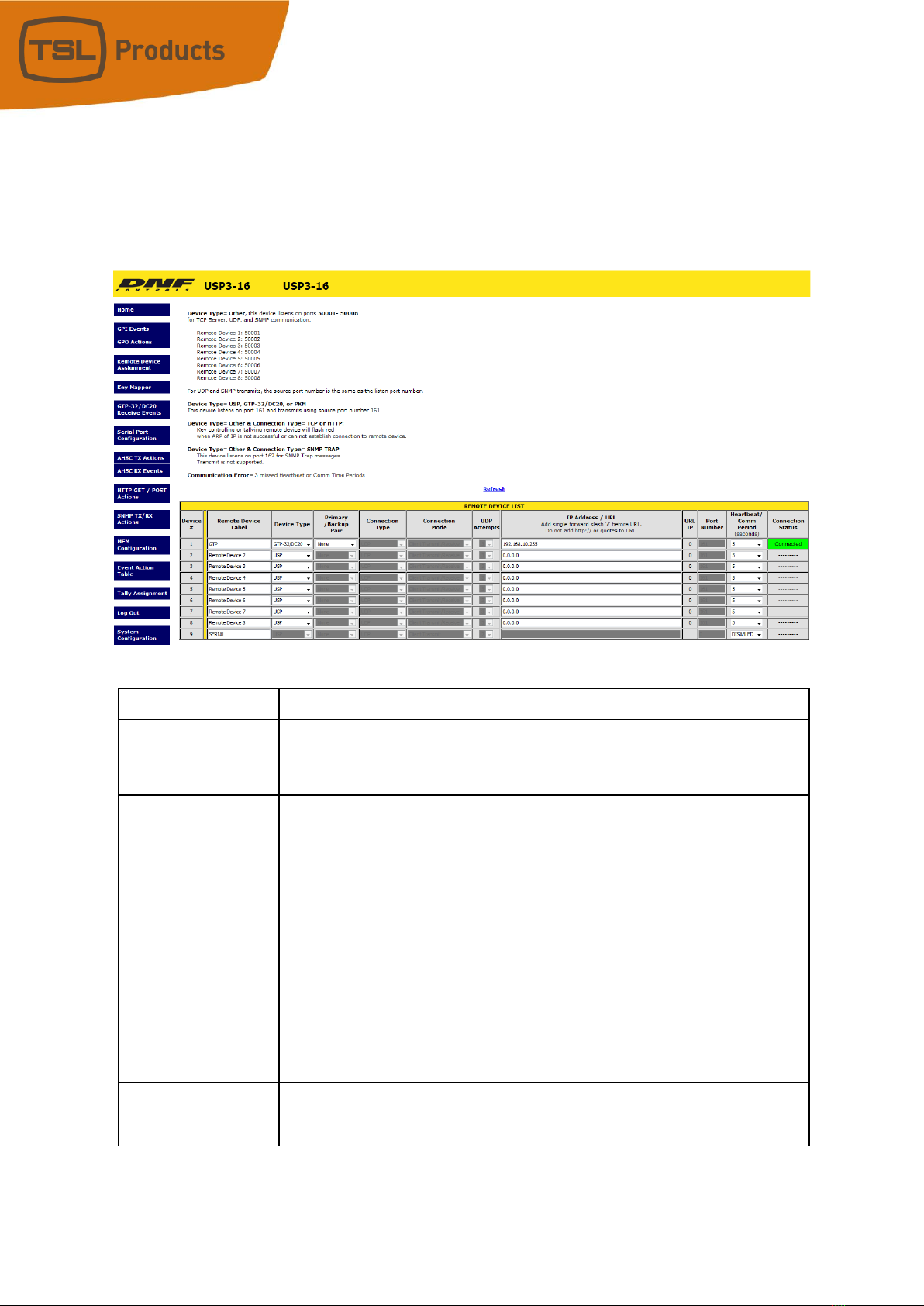
Remote Device Assignment
Use this page to identify the remote USP’s, GTP-32’s, AIB’s, or other devices that the local
USP will communicate with. If the USP3 will operate standalone, this page may be left
blank.
PARAMETER
DESCRIPTION
Remote Device
Label:
Enter a unique device description/ identifier, up to 32 characters in length
that clearly identifies the remote device. This description/ identifier will
appear in the remote device list that is used on the other configuration
pages.
Device
Type:
GTP-32/DC20:
Select to connect to a DNF GTP-32 or DC20/21.
USP:
Select to connect to other DNF Controls Universal Switch Panels and
AnyWhere Interface Boxes.
USP3-API:
Select to connect to a 3rd party for direct control over the USP3.
PKM:
Use to connect to PC for Keymapper functionality.
OTHER:
Select to connect to a Ethernet Device.
Connection
Type:
For OTHER Device Types only-
Select UDP, SNMP, SNMP Trap, TCP/IP or
HTTP GET/POST

USP3 User Manual Page 20 of 73
Connection
Mode:
For TCP/IP Only
Client Transmit: Establish connection to remote device.
Transmit command.
Disconnect from remote
device.
Client Transmit/Receive: Establish connection to remote device.
Maintains connection to remote device.
ServerReceive/Transmit: Accept connection from client.
Only client at assigned IP Address can connect.
The client is responsible for maintaining
connection.
Server Mode only
USP3 listens on the following ports:
Port 50001 for connection from Remote Device 1
Port 50002 for connection from Remote Device 2
Port 50003 for connection from Remote Device 3
Port 50004 for connection from Remote Device 4
UDP
Attempts:
For UDP Connection Type only.
The number of times that the message will be sent separated by 10
milliseconds. Since UDP does not provide guaranteed delivery, UDP
Attempts provides more than one transmit attempt to deliver the
message.
IP Address / URL:
Enter the IP address or URL for the remote device to be controlled or
monitored.
URL IP:
Display the IP address associate with URL.
Port
Number:
Destination port number for transmit actions
Source port number for receive events. Set to ‘0’ to receive events
from
any port number at remote device IP address.
Heartbeat
Rate:
For USP and GTP-32/DC20 Device Types.
Default value is 5 seconds.
Communication error is defined as loss of
two consecutive heartbeats.
Connection
Status:
For USP and GTP-32/DC20 device types and TCP/IP connection types only
Displays “Connected” in green when communicating with remote device
Displays “---------“when NOT communicating with remote device or no IP
address has been entered.
Save Button:
Click on Save button to save entered settings
Refresh Link:
Click on Refresh link to refresh Connection Status
This manual suits for next models
3
Table of contents
Popular Dj Equipment manuals by other brands

Solid State Logic
Solid State Logic C100 HDS Software Update Manual

ETS Lighting
ETS Lighting LED CityColor 1000 Head Control user manual

Equinox Systems
Equinox Systems EQLED039A user manual
Robe
Robe pixelPATT user manual

Ibiza
Ibiza LED8-MINI user manual

Cyclops Lighting
Cyclops Lighting PAR-350W user manual


