Aqua AQUA-STEAM GENERATOR 1 User manual

INTRODUCTION
Contents
Page 2
TECHNICAL SPECIFICATION Page 2
INSTALLATION & FITTING Page 5
TYPICAL INSTALLATION (FIGURE 1) Page 4
AUTO FLUSHING GENERATOR (FIGURE 2) Page 7
DESCALING Page 11
Please read all of the instructions carefully before commencing installation or using the facility.
PROBLEM SOLVING GUIDE Page 13
INDICATORS Page 12
OPERATING INSTRUCTIONS Page 9
COMMERCIAL STEAM GENERATOR
Installation Instructions

Page 2
INTRODUCTION
AQUA STEAM 6-12Kw BKW and AQUA STEAM 18-24Kw BKW
The AQUA-STEAM GENERATOR series have many unique features that make them superior to other steam
generators in the market place. They have been designed to give maximum performance, easy installation,
easy operation and low maintenance costs. The most important point of all for the user is that they produce
the freshest steam possible! Steam quality can deteriorate due to poor water quality and this can result in
unpleasant odours’. The AQUA STEAM GENERATORS overcome this problem with a unique patented automatic
solids reduction system that ensures that solids in the water are kept to a minimum and water freshness to
optimum purity with our automatic ushing facility which drains the stale water.
The commercial control is electronic with digital display of required temp (set point) actual temperature and a 7
day timer. The cubicle control and temperature sensor are stainless steel and pre-wired for easy installation.
The 22mm steam outlet is polished metal and has a venturi essence diuser.
Various sizes of steam generators are available to suit the particular size and materials used in the construction
of the steam enclosure. Each model of steam generator has three power settings. (See table below). This allows
our generators to cover various sizes of steam rooms.
MODEL POWER SETTINGS
1 COMMERCIAL BJ 6-12KW 6,9,12KW
2 COMMERCIAL BJ 18-24KW 18-21-24KW
Please note that whatever steam generator from which ever manufacturer you choose the water quality is of
paramount importance. Poor water quality will inevitably mean more frequent servicing. The BJ series of
auto ush generators with the patented solid reduction system greatly reduces servicing down time compared
to non patented systems.
TECHNICAL SPECIFICATION
AQUA-STEAM GENERATOR BJ SERIES
The following chart is for guidance only and for cubicles that are insulated to manufacturer’s guidelines
NOTE: Should the insulation not be adequate; allow extra power (KW’s) for heat loss
CUBICLE SIZE
FOR MASONRY
MATERIAL
CUBICLE SIZE
FOR PLASTIC
MATERIAL
SUPPLY
CURRENT
POWER
SUPPLY
POWER
SUPPLY
CUBIC METRES CUBIC METRES AMPS 1 PHASE 3 PHASE
6Kw 2.5 - 8.0 Cu.Mtr. 4.0 -15.0 Cu.Mtr 25 amps 4mm sq 1.5mm sq
9Kw 7.0 – 16.0 Cu.Mtr. 13.0 – 24.0 Cu.Mtr 38 amps 6mm sq 1.5mm sq
12Kw 14.0 – 20.0 Cu.Mtr. 22.0 – 30.0 Cu.Mtr 50 amps 3 phase 4mm sq
18Kw 18.0 – 30.0 Cu.Mtr. 28.0 – 40.0 Cu.Mtr. 76 amps 3 phase 4mm sq
24Kw 28.0 – 40.0 Cu.Mtr. 38.0 – 50.0 Cu.Mtr. 100 amps 3 phase 6mm sq

Page 3
If the cubicle is not square allow ½ KW for masonry material and ¼ Kw for plastic material per extra square
meter of surface created. These examples are for a cubicle at 40˚c for higher temperatures additional power or
lagging may be required.
POWER SUPPLY 220-240 volts AC.50-60 Hz BJ6-12A single phase or three phase. BJ18-24A
three phase only.
POWER SETTING ADJUSTABLE Cable size must be determined before installation and adequate for the
maximum power setting to be used.
ELECTRONIC CONTROLS User friendly electronic controls, factory wired (plug in) 12 volts DC, 7 day
timer.
HEATERS Incaloy industrial rated heaters, each 3kW 240 volts (approx 20 ohms
resistance.)
OPTIONAL AUXILLIARY OUTPUT A terminal connector with fuse, up to 5 amp synchronised with heaters,
which may be used to power an essence dosing system if required.
FUSES. The system must be cabled and fused correctly to suit the above sup-
ply current requirements. All heaters are protected with a manual reset
Hi-limit. Control electronics is protected by a 3.15 Amp slow blow fuse.
Essence diuser unit protected internally with 5 amp max cartridge fuse.
WATER SUPPLY Minimum working pressure 0.5 bar. Maximum working pressure 10
bar, 3/4" male thread for connection to washing machine type hose.
Note that the generator has an approved water inlet valve but in certain
areas, particularly commercial units it may be a requirement to install a
double check valve or RPZ (reduced pressure zone) anti pollution valve to
eliminate all possibility of the water supply becoming contaminated.
STEAM OUTLET 22mm max length 20 Metres pipe must be lagged adequately. NOTE BJ18-
24A is supplied with two steam outlets. If pipe is longer than 10 Metres
add an extra kW.
TWO STEAM SAFETY FEATURES
IN.
1. Manual reset cut out.
2. Pressure safety valve.
STEAM GENERATION Up to 1.4kg of steam per kw per hour. Constant steam.
HEAT EXCHANGER 316 Stainless steel tank, constructed with, easily removable external
access caps for easy cleaning.
CONSTRUCTION For the prevention of corrosion the external casing is powder coated
zinc plated steel and all internal components are of corrosion resistant
materials.
PATENT DESIGN AUTO
FLUSHING UNIQUE REDUCTION
SYSTEM
A water softener is not normally required if regular cleaning is carried
out or an Aqua-soft is tted (Auto descaler) Note A 15mm waste pipe is
necessary for discharging waste water that is near boiling point. Use a
washing machine type stand pipe or other suitable drain.
ESSENCE DEFUSER UNIT Terminal connector with fuse, up to 5 amps synchronised with heaters.
OPTIONS Auto de-scale unit available.
These units are manufactured in accordance with the European standard EN 60 335-2-15:1990.
Electrical power must be supplied via an appropriately sized cable, a residual current circuit breaker (rated at
30ma amps sensitivity) together with a local isolating switch with 3mm break for all poles and terminal fuses to
suit supply current.
This unit is manufactured in accordance with the European standard-EN 60 335 - 2 - 15: 1990 Electrical power
must be supplied via a residual current circuit breaker (rated at 30mAmp sensitivity) together with an isolating
switch with 3mm break per pole for all poles and supply fuses to suit supply current.
TO BE INSTALLED TO NATIONAL STANDARDS BY A QUALIFIED ENGINEER

Page 4
TYPICAL INSTALLATION (FIGURE 1)
FIGURE 1
PLEASE NOTE THIS DIAGRAM IS NOT TO SCALE

Page 5
INSTALLATION & FITTING
COMMERCIAL STEAM GENERATORS
BJ6-12AkW & BJ18-24AkW
BJ6-12BkW & BJ18-24BkW
NOTE: - Before the installation of this machine, please make sure you read these instructions thoroughly Failure
to install this machine in accordance with the manufacturers recommendations might invalidate the warranty.
Should you have any queries or require technical advice, contact your distributor who will put you in contact
with our technical department. The electricity supply must only be connected to the unit by a suitably qualied
person in accordance with local regulations.
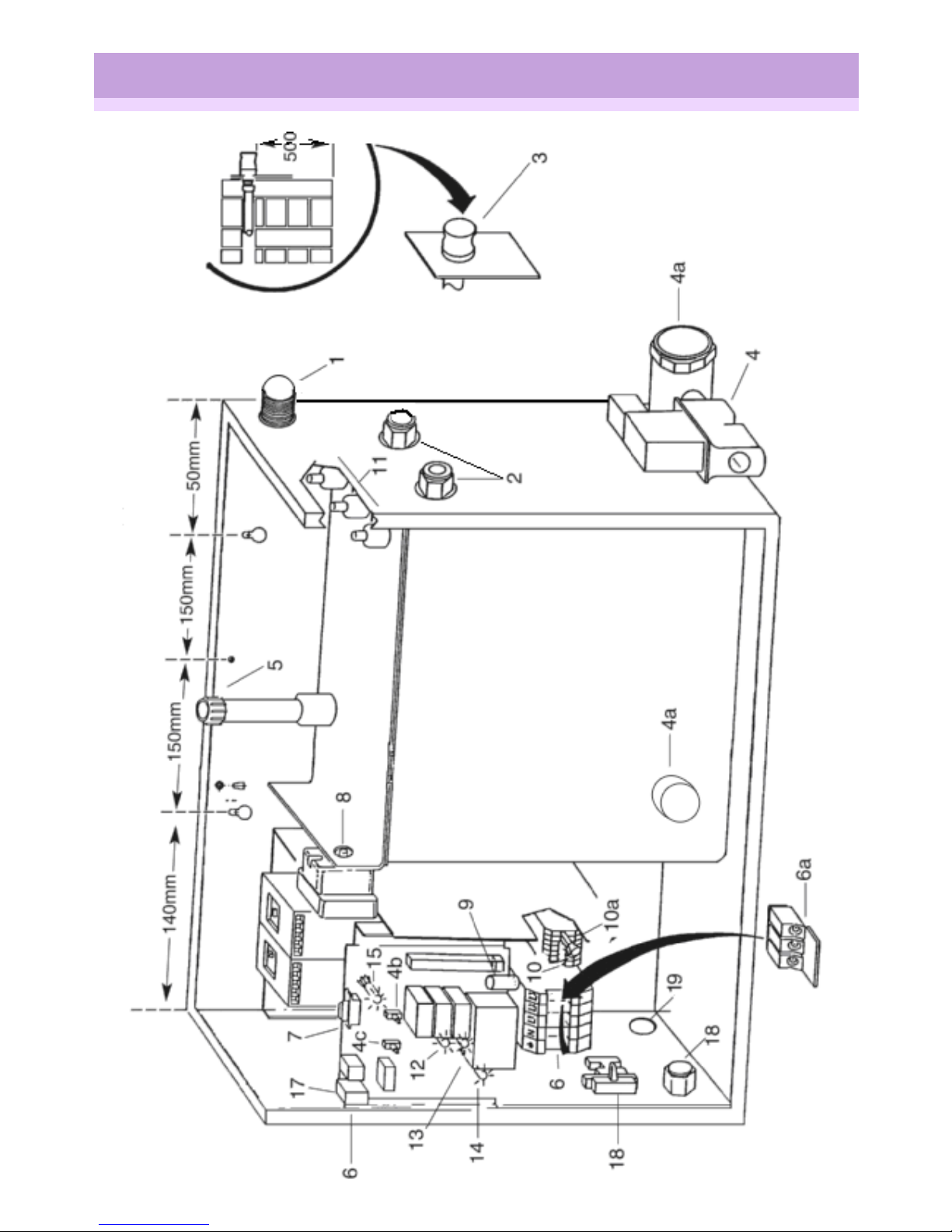
STAGE ONE: - Sighting and Fixing the Generator.
A minimum space of 1100mm for width and 1000mm for height should be allowed, with proper access for
servicing the generator and the descaling cap. (See detail 5 Fig 2) Determine a clean dry place where the steam
generator is to be xed (emphasis on the surface being secure and the unit being properly supported). The unit
is not suitable for installation in a damp or wet area. Screw the generator to the wall, through screw holes (see
dimensions on Fig 2) Make sure the generator is both vertical and horizontally level. Allow 300mm minimum
height from the oor, to leave space for drainage of solids into a container. A minimum space of 400mm from
the cleaning access cap(s) (see Fig 2) from the unit should be permitted for cleaning with the brush provided.
Once the generator has been xed, the anchor screw must be tted to prevent the generator from being
accidentally moved. Should the generator be boxed in, an access door or panel must be tted to allow for easy
access and maintenance of the generator unit without damaging the decoration, you should also make an
allowance for ventilation minimum 100mm x 100mm.
STAGE TWO: - Water Supply
Generally the water supplied from any regional water authority is of sucient quality to use with the Aqua-
Steam generator. Greater care is perhaps required if water is from a well or bore hole particularly if the
iron content is high. Such water should be avoided. If requested the water authority will advise on the scale
content (hardness) of the water supplied. In situation where the water hardness is greater than 100 ppm it is
recommended that a monospheric water softener be incorporated to supply the generator especially if the
unit is to be in frequent use. Alternately inspect the unit for scale after every 100 hours of use and de-scale as
necessary – see descaling instructions. We recommend that a washing machine hose is tted to the 3/4” BSP
male thread of the solenoid valve (detail 1 Fig 2) and connect the other end of the hose to a servicing valve so
the water supply can be isolated. The hose is also useful for ushing the tank and pipe work during maintenance
etc. A minimum water pressure of 0.5 bar and maximum 10.0 bar must be provided for the correct operation of
this machine.
STAGE THREE: - Fitting Steam Outlet
The maximum pipe run must not exceed 20 Mtrs length and must be of 22mm diameter. The pipe work should
be installed in such a way as not to create air locks. Long radius bends should be used or pulled bends to reduce
restriction of steam. The pipe must be adequately lagged to avoid heat loss and condensation of steam. The BJ
18-24 generator has two independent steam outlets; each must be tted as above but totally independent from
each other. When pipe is increased over 10 Metres a higher power setting may be necessary. It is bad practice
and a frequent source of failure to inject essence into the steam pipe(s). Even in very large diameter pipes the
llers and plasticisers used in the essence quickly block the pipe and also back up into the generator.
STAGE FOUR: - Auto-ushing
Connection to the discharge solenoid valve is 1/2” BSP thread and the drain line must be a minimum of 15mm
diameter heat resistant pipe and must have a minimum fall of 1.5 degrees to an open drain, washing machine
trap or similar. Keep the pipe run short with as few bends as possible as it will otherwise ll with scale.
STAGE Five: - In the Cubicle
Fit either the BKW temperature sensor or the AKW cubicle control. The BKW sensor should be tted
approximately 2Mtrs above the oor away from the steam outlet in a safe position. The AKW cubicle control if
tted should be approx l.8mtrs above the oor away from the steam outlet. We recommend that shower type
silicone sealant be used around the stainless steel trim and box assembly of the cubicle control to x the unit to
the wall. Connect plug on lower right hand of attendant control box.

Page 6
STAGE SIX: - Fitting 12v Electronic Attendant Control9
This control must be tted in an easily accessible dry place for the operation of the attendant. When the control
is tted to the wall then connect plugs coming from the control to the sockets on relay board inside left hand
of generator box. NOTE extension leads are available if required. Also make sure exposed connectors are
protected with water proof tape.
STAGE SEVEN: - Computer Management Link
You only need to connect a 2 wire lead with a gland inside lower left hand of attendant control. These wires
must go to a volt free contact at the computer, when contact is made (closed) generator will start, when contact
is (open) generator will stop. NOTE: control switch must be on timer mode and the timer switch “OFF” to
synchronies with computer. This function is available as standard on the AKW control but only by special order
on the BKW control.
STAGE EIGHT: - Power (Kilowatt) selection for BJ6-12 & BJ18-24
For BJ6-12 the xed minimum power is 6kW. To increase to 9kW insert link pin (detail 10 Fig 2) and to increase to
12kW also insert link pin (detail 10A Fig 2). For model BJ18-24 the minimum xed power is 18kW. To increase to
21KW t link pin (detail 10 Fig 2), to increase to 24KW t link pin (detail 10A Fig 2). Link pins are to prevent power
being accidentally increased. Cable should be adequately sized to suit the power requirement. Note: setting the
generator on a higher power than necessary may result in the cubicle remaining for relatively long periods at a
temperature above the set point with no steam. Only use the minimum power necessary.
STAGE NINE: - Connection to Power supply
The BJ6-12 is set for three phase but can be modied to single phase use by inserting a link connector supplied
(detail 6A Fig 2) into connector (detail 6 Fig 2). By tightening the three screws the machine will be converted into
single phase operation. The BJ18-24 is three phase only. When connecting cables to power supply it is advised
that conduit be used and connected via hole (detail 6B Fig 2) with the appropriate tting. 220-240v AC. for single
phase, 415v AC. for three phases 50-60Hz. The steam generator must be earthed and connected to a residual
current circuit breaker with a minimum of 30 mille Amps sensitivity and connected through an isolating switch
with minimum of 3mm breakage across all poles. The correct fuse must be tted for the power selected. For
technical specication see page 2. NOTE all mains connections must be thoroughly tightened and it is good
practice to re-tighten all power connections within the generator since copper conductors may have “eased
back’’ in their terminals in transit.
STAGE TEN: - Essence Doser unit (optional extra)
This machine is provided with a 220-240v AC. 5 amp fused terminal connector (detail 18) and PG7 cable gland
(detail 18A) for essence doser connection, this will energies when steam is produced. For further details contact
your supplier.
STAGE ELEVEN: - Commissioning Generator
Re-check that the unit is installed in accordance with the instructions before switching mains power on. Please
check that the water supply is “ON” with sucient pressure 0.5 bar, (3 meters head). Switch power “ON” and
you will see a green light on the generator and an intermittent one on the AKW attendant control or a further
steady green light on the BKW control (that means the generator is ready to start) now follow the operating
instructions. Once the generator is operating switch o and drain the generator to clean plumbing ux etc from
inside. Do this twice and nally check for leaks. If you need any further information please do not hesitate to
contact our technical department.
Please leave instructions with client and demonstrate how to de-scale the unit.

Page 7
AUTO FLUSHING GENERATOR (FIGURE 2)
FIGURE 2

Page 8
Description Item No
Inlet water Solenoid 1
Safety Valves 2
Steam Outlet Nozzle - 22mm Commercial 3
Outlet Solenoid 4
Cleaning access 4A
Manual Dump 4B
Manual Fill 4C
Steam out let connection & Descaling input cap 5
Electrical terminals 6
Single-three phase link 6a
Relay PCB - Domestic Board 3-9kW 7
Safety Cut Out 8
PCB Board Fuse 9
Terminal Block For KW Change 10
Terminal Block + KW Change Pins 10a
Set Of Probes- Aqua-Steam Generator 11
Indicator Heater ON 12
Indicator Water ON 13
Indicator Power ON 14
Indicator Generator State 15
Generator Case 16
Connector SK2 power for control 17
Optional auxiliary terminal & cable gland 18
Electric cable input 19
Contactor
Set of Elements 6-9-12Kw or 18-21-24Kw
Heater Element C/W Cut Out
5 Metre Extension Lead & Plug
Commercial Control Panel
PARTS LIST

Page 9
OPERATING INSTRUCTIONS - AKW CONTROL
ATTENDANT CONTROL (All connections to the control unit are 12V A.c. or D.C.)
Unlock the clear lid with a screw driver. Then press the side next to the lock and the clear lid will open, press the
control “ON” the system is then in standby mode and you should see a green intermittent light, this means the
power is on and you can start to operate the generator in one of three ways.
CUBICLE CONTROL STANDBY 32 MINUTES AUTO STOP MODE
To operate in this mode, you must rst set the switch on the attendant control to “32 minutes auto”. The steam
generator will only work when the user inside the cubicle pushes the start button. A red intermittent light will
indicate that the generator is “ON” then it will stop automatically after 32 minutes.
ENERGY SAVE AUTO-STOP 32 MINUTES
This mode is normally used by the attendant in periods when the cubicle is not busy so as to save energy. You
can switch the cubicle on for 32 minutes by pressing the top left button next to the time remaining indicator and
you can stop the system by pressing the lower button.
SEVEN DAY TIMER MODE
With this function you can program the generator to be switched “ON” Twice and “OFF” Twice during each
individual day of the week. (Minimum “ON” time is two hours).
COMPUTER LINK MANAGEMENT SYSTEM (optional extra)
This link will allow you to switch the generator “ON” or “OFF” from a computer but the control switch must be
positioned in “timer mode” and the timer switch must be “OFF” for the computerised system to take control.
TEMPERATURE ADJUSTMENT
You can adjust the temperature by pressing the arrows up and down next to the thermometer, where an
intermittent light tells you the setting of the temperature and a series of steady lights tell you the actual cubicle
temperature.
If you switch o the attendant control unit you will over-ride the computer link and any other function for
servicing and in an emergency always switch the generator “OFF” at the mains.
Note that the generator is supplied with the temperature pre-set at 35C In order to change this setting rst
set the temperature required as described above and then turn the control o by using the OFF button on the
touch pad. When restarted, the system will then start up using your preferred operating temperature.
OPERATING INSTRUCTIONS - BKW CONTROL
ATTENDANT CONTROL (All connections to the control unit are 12V A.c. or D.C.)
Unlock and open the clear lid as described in the AKW instructions above.
7 DAY TIMER
With this function you can program the generator to be switched “ON” Twice and “OFF” Twice during each
individual day of the week. (Minimum “ON” time is two hours).
OPERATING INSTRUCTIONS BJ6-12KW & BJ18-24KW

Page 10
COMPUTER LINK MANAGEMENT SYSTEM
This link will allow you to switch the generator on or o from your computer but the timer switch must be in the
o position. This function is only available by special order.
TEMPERATURE ADJUST
The digital thermostat displays the temperature at the sensor in the steam room, to display the set point press
and hold the thermometer button. Should the set point need adjustment continue to hold the thermometer
button and at the same time use the up or down arrow to select the required temperature. Release all buttons.
START UP DISCHARGE
The BKW control is designed so that it may also be used in conjunction with an Automatic Descaler. When
descaling is completed and the generator restarts a brief heating cycle (10 seconds approx) is initiated followed
by a 4 minute discharge (approx) and delay before the generator rells and starts to heat up. This discharge can
be over-ridden by using the on/o switch on the bottom right of the control, turning it on, o and on again.
REMOVAL OF WATER DEPOSITS
If a water softener is tted always ensure that it is not allowed to function without salt and that it only back
washes at a time when the steam generator is not in use. If the water softener is working correctly removal of
water deposits will not normally be necessary. When the steam generator has cooled down drain the generator
by holding the “DUMP SWITCH” on the control isolate the machine at the main power switch. Then place a
container of minimum of 5ltr capacity under the lower access cap. Remove the access cap by hand, turning anti-
clockwise, releasing the water residue. With the brush provided clean inside the bottom of the tank to remove
any akes of scale. Replace access cap hand tight only; please be careful not to cross the threads. Check for
leaks. Switch on mains power and your regular maintenance is now complete.
SCALE
Scale is the primary concern in heavily used generators and an auto de-scale unit is available for use in
conjunction with th BKW control and commercial generators. The auto de-scale adds descaler to the generator
when it is switched OFF at night. It is a feature of the BKW control that at start up from the time clock the
generator will be instructed to heat for a few seconds and then dump the entire contents of the tank over a 4
minute period, to remove any descaler that may have been added. This ensures that the unit contains fresh
water before steaming begins. If an auto de-scale unit is not tted or during testing, the 4 minute delay period
can be overridden by switching the control ON/OFF switch from ON to OFF and back to ON again.

Page 11
DESCALING
The steam generator manufacturer cannot accept responsibility for the quality of the water fed to the unit.
Water quality varies from area to area and with the time of the year. Any warranty will be invalid if the generator
is not kept free of water solids and scale. This means ensuring only adequate clean water is supplied to the
generator i.e. less than 100 parts per million of impurities. (See note 2) The steam generator must be checked
regularly and if necessary de-scaled. If there is any doubt it is better to de-scale the unit and typically this
will need to be done every 100 hours of operation. Descaling is a relatively simple task but is important in
order to keep the steam generator in good condition and prolong the life of the unit. The auto ushing Steam
Generator will greatly reduce the build up of scale and ensures optimum freshness of steam. The frequency at
which descaling is necessary is also greatly reduced compared to other manufacturers products which do not
incorporate the patented auto ush system.
If a water softener is tted make sure that this does not recycle when the generator is in use. Descaling may
need to be carried out every 100 hours of use in very hard water areas. For safety reasons only use citric acid
descaler from your supplier.
During descaling the machine must be isolated from the electricity supply at all times, never use this appliance
during descaling and make sure that all the de-scalent is removed before the steam facility is used again.
1. For the purpose of descaling steam generators, use non poisonous and non corrosive de-scalent (citric acid.)
2. Allow the generator to cool before remove the descaling cap by turning anti-clockwise. Mix the de-scalent to
manufacturers instructions and with a funnel pour the solution into the generator. Fit the ller cap back on the
unit.
3. Leave the de-scalent in the generator for as long as instructed. (Typically 5-24 hours)
4. Flush the generator thoroughly to ensure that all traces of de-scalent are removed. Note that with the tank
empty it is useful to unscrew the 40mm access cap (detail 4a Fig 2) and clean out any large pieces of scale that
may remain. The auto-ushing steam generator will rarely need descaling unless the water quality is extremely
poor. The service engineer will nd a push button inside the cover to open the electrical ushing valve manually
if necessary.
NOTE: In severe cases some de-scalent may enter the steam pipe and the steam outlet, should this happen the
pipe must be ushed with clean water, from time to time this is also useful to prove that the steam pipe is not
blocked.
FLUSHING
Optimum steam quality can only be achieved if the generator is lled with the purest possible water. Boiling or
extremely hot water could be released when the drain valve (see detail 4) is opened so it is important that due
care be taken and preferably that the unit should be allowed to cool slightly before the drain valve is opened.
If a water softener is tted and working correctly descaler should not be needed however an unmaintained
softener will provide no protection against scale. It is advisable to inspect the inside of the tank at least every
month. If proper maintenance is not carried out and scaling occurs for any reason warranty of the tank will be
void.
WARNING:
During descaling the machine must be isolated from the electricity supply at all times. Never try to use the
appliance during descaling and make sure that all the descaler is removed before the steam facility is used
again.
CAUTION:
The user must be made aware that due care must be taken particularly with children and the inrm when using
this equipment. If in doubt seek medical advice. Leave the instructions with the client and ensure that they
understand how to use the facility.
NOTE: To prolong the life of the generator and reduce the inconvenience of manual descaling an automatic
descaling unit is available from your distributor

Page 12
INDICATORS
AKW INDICATORS CONTROL UNIT
The two alternating green indicators at the bottom of the thermometer show that low voltage power is
available at the control unit. When the control is turned on the steady indicators on the thermometer show the
temperature. The ashing indicator on the thermometer shows the current set point (or required temperature).
The clock indicators each represent 4 minutes giving 32 minutes if all are on.
BKW INDICATORS CONTROL UNIT
When the control is active the digital display shows the temperature. To check the set point press ******* If
adjustment is required then press the up and down arrows as necessary. Once set the display will resort to
displaying the actual temperature after approximately 5 sec.
STEAM GENERATOR INDICATORS
There are four indicators on the Steam Generator see Fig 2:-
Item 14 GREEN Shows mains supply is connected to the generator and switched on.
Item 12 RED (upper) Comes on whenever the control is on and the generator requires more
water.
Item 13 RED (lower) Comes on whenever the heaters need to be on to make steam.
Item 15 YELLOW Comes on whenever the supply is on and will change to green only when the
control temperature is above the set point.
Item 15 GREEN Cubicle has reached set temperature
Item 15 RED Error state impurities in water or water has reached the high probe

Page 13
SYMPTON PROBABLE CAUSE REMEDY
1. No Green light on control box Main power isolator switched o Ensure mains power is on and
check for green light on generator
2. No steam from unit Control turned o Turn on at cubicle control
3. No steam from unit Water supply inadequate Water turned o or blocked or very
low pressure
4. Steam inadequate Temperature too low Set temperature higher as per op-
erating instructions
5. Steam inadequate Cubicle not properly lagged or
power too low
Consult installer
6. Steam inadequate Impure water Flush generator twice by opening
drain valve and re-lling twice
7. Steam inadequate and unit stops Over temperature reset tripped
due to blocked steam outlet
Consult installer
NOTES THE MOST FREQUENT CAUSE OF PROBLEMS ARE:-
1. Insucient water, water pressure low or the supply interrupted by other services i.e. showers, pumps etc.
Water inlet blocked, poor water quality or water impurities.
2. Failure to provide drainage facilities.
3. Failure to keep the generator clean i.e.
Not ushed clean after installation.
Not ushed after water softener service.
Not ushed after descaling.
Not ushed after local pipe work.
Not ushed after local water mains work.
Not ushed for a long period of time.
Drain pipe blocked.
4. Failure to descale tank periodically say every 100 hours use in hard water area (1000 hours in soft water
areas.)
5. Steam outlet blocked due to damage, poor installation, vandalism or essence dosing.
6. Heater failure may cause an earth- leakage trip to occur.
7. Poor ventilation of steam generator.
PROBLEM SOLVING GUIDE

Page 14
IMPORTANT NOTICE
If this unit should fail to work properly please re-check the following:-
1. The unit has been installed in accordance with the instructions in a vertical position as shown in gures 1 & 2.
2. Electrical power is reaching the unit.
3. Water supply is reaching the unit and the input has not become blocked with swarf or sediment.
4 The steam pipe or the steam outlet has not become blocked.
WARRANTY
The supplier may exchange recondition or repair the unit on a return to base service at his discretion provided
it is still within the warranty period. No responsibility can be accepted if the unit has been tampered with by
unauthorized personnel. The most common cause for failure is poor water quality (i.e. impurities or scale)
COPYRIGHT Aqua-Steam Generators Limited E & O E
This manual suits for next models
1
Table of contents