Eliminator 011-1846-6 User manual
POWER/
PUISSANCE
8.8.8.
INPUT//ENTRÉE
(V)
OUTPUT/SORTIE
(KW) (W)
REMOTE ON/OFF
INTERRUPTEUR TÉLÉCOMMANDE
USB
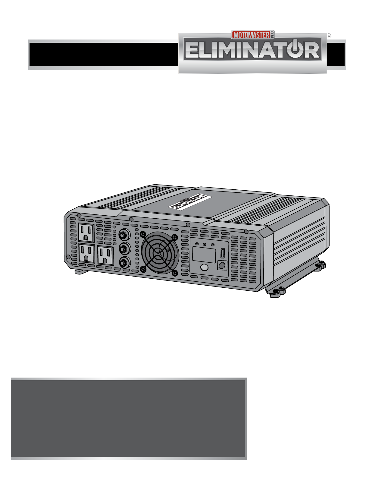
3000 W
Digital Power Inverter
Onduleur Portatif Numérique
011-1846-6
INSTRUCTION
MANUAL
3,000 WATT MODIFIED SINE
WAVE DIGITAL INVERTER
model no. 011-1846-6
IMPORTANT:
This manual contains important safety and
operating instructions. Read all instructions and
follow them with use of this product.

2
3
model no. 011-1846-6 | contact us 1-877-619-6321
DO NOT RETURN THIS PRODUCT TO THE STORE!
QUESTIONS? CALL CUSTOMER SERVICE, HOTLINE: 1-877-619-6321
TABLE OF CONTENTS
TABLE OF CONTENTS
Safety Information 4
Key Parts List 8
Important Information 10
Assembly Instruction 19
Operation 27
Maintenance 29
Troubleshooting 30
Technical Specification 32
Warranty 33

4
model no. 011-1846-6 | contact us 1-877-619-6321
SAFETY INFORMATION
SAFETY INFORMATION
This manual contains information
that relates to protecting personal
safety and preventing equipment
problems.
Carefully read and follow the
guidelines in this manual and give
special attention to the caution and
Warning statements.
ABBREVIATIONS AND
ACRONYMS
A Amp (Ampere)
AC Alternating current
cm Centimeter
DC Direct current
kW Kilowatt
mm Millimeter
V Volts
W Watts
SHOCK HAZARD
• Keep children away from the
Digital Power Inverter. Do not
allow children to handle the
Digital Power Inverter.
• DO NOT expose the Digital
Power Inverter to rain, snow,
spray, or bilge water.
• Make sure the inverter wiring is
of proper size and rating and in
good condition. Operating the
inverter with damaged wiring
may void warranty.
• DO NOT use the inverter if it is
dropped, hit, worn, broken, or
damaged.
• DO NOT attempt to service or
disassemble the inverter, as it
does not have user-serviceable
parts and the internal
capacitors remain charged
even if the power source is
disconnected.
• Disconnect DC power source
from the inverter, before
attempting to service, clean,
or operate on any circuits
connected to inverter. Simply
turning OFF the ON/OFF
switch of the inverter will not
disconnect the power, thereby
causing electric shock.
• NEVER connect the inverter to
any power distribution systems
or branch circuits.
• While servicing, never work
on the AC wiring without
physically disconnecting the DC
connection.
• Use care when operating
110 V circuit. Incorrect
operation of the inverter may
cause personal injury.
• Digital Power Inverter is not
designed to be waterproof.
It functions in ambient
temperatures of -10°C to 40°C.
EXPLOSION AND FIRE
HAZARD
• NEVER operate the inverter
near flammable items or
explosives, such as in cabin
of a gasoline powerboat, or
near propane/fuel tanks, in
compartments containing
batteries of flammable
materials, locations that
require ignition-protected
equipment, joints, fittings or
any connections between
fuel system components. This
inverter contains components
which tend to produce arcs or
sparks.
• NEVER smoke while handling
the inverter.
FIRE HAZARD
• DO NOT cover or obstruct the
ventilated openings of the
inverter, as doing so may cause
overheating.
• Make sure there is minimum
of 3” (7.5 cm) of unblocked air
space around the entire surface
of the inverter at all times. The
inverter may become warm
reaching a temperature of 140°
F (60°C) under high power
operation.
• DO NOT place any materials
near the inverter, that could be
easily damaged by heat.
EQUIPMENT DAMAGE
• Do not connect inverter to live
AC power circuits or any AC
device with neutral conductor
connected to ground, to avoid
damage to the inverter even if it
is switched OFF.
• Never install the inverter in a
zero-clearance environment,
as doing so may cause
overheating of the inverter.
5
SAFETY INFORMATION

6
7
model no. 011-1846-6 | contact us 1-877-619-6321
SAFETY INFORMATION
SAFETY INFORMATION
SAFETY PRECAUTIONS
WHEN WORKING WITH
BATTERIES
Follow all instructions mentioned
by the manufacturer to avoid
explosion of the battery.
EXPLOSION HAZARD
• DO NOT work near lead-acid
batteries, as the batteries
generate explosive gases during
normal operation.
• DO NOT drop a metal tool on
the battery, as doing so can
create spark or short circuit in
the battery or other electrical
parts, resulting in battery
explosion.
• While removing the battery,
make sure to remove grounded
terminal from the battery and
disconnect other electrical
connections.
• Make sure the area around
the battery and engine is well
ventilated and free from spark
or flame.
• Do not operate the inverter in
an enclosed area containing
automotive type lead-acid
batteries. These types of
batteries emit explosive
hydrogen gas that can be
ignited by sparks.
• Have someone within the range
of your voice or nearby for help
when working with the lead-
acid batteries.
CHEMICAL HAZARD
• Remove all metal items such as
rings, bracelets, and watches
when working with the lead-
acid batteries. The batteries
may produce short circuit
current that can weld metals,
thereby causing severe burns
on skin.
• Make sure there is plenty of
fresh water, soap and baking
soda near the work area. If
a person’s skin or clothing
accidentally contacts with
battery acid, wash immediately
with baking soda, soap and
water. If the acid enters eye,
wash immediately with running
cold water for minimum twenty
minutes and get medical
attention immediately.
• Always wear complete eye
and clothing protection. Avoid
touching your eyes while
working with the batteries.
EQUIPMENT DAMAGE
• Connect the inverter to batteries
with a normal output of 12 V
DC only. The inverter will not
operate if connected to a 6
V battery (voltage is too low)
and 24 V battery (voltage is too
high) will damage the unit.
• DO NOT insert any foreign
objects into the outlets, vents,
or fan openings of the inverter.
• DO NOT cover or obstruct the
ventilation openings of the
inverter.
SAFETY PRECAUTIONS
WHEN USING
RECHARGEABLE
APPLIANCE
• Please connect 4 cables with all
4 DC terminals according to the
installation instructions in this
manual. Failure to do so may
damage the inverter.
• DO NOT use this inverter to
recharge battery operated
appliances such as flashlights,
razors, and night lights that can
be plugged directly into an AC
outlet.
• DO NOT use this inverter to
recharge battery operated
power tools that have a charger
with a warning label indicating
that dangerous voltages are
present at the battery terminals.
8
model no. 011-1846-6 | contact us 1-877-619-6321
SAFETY INFORMATION
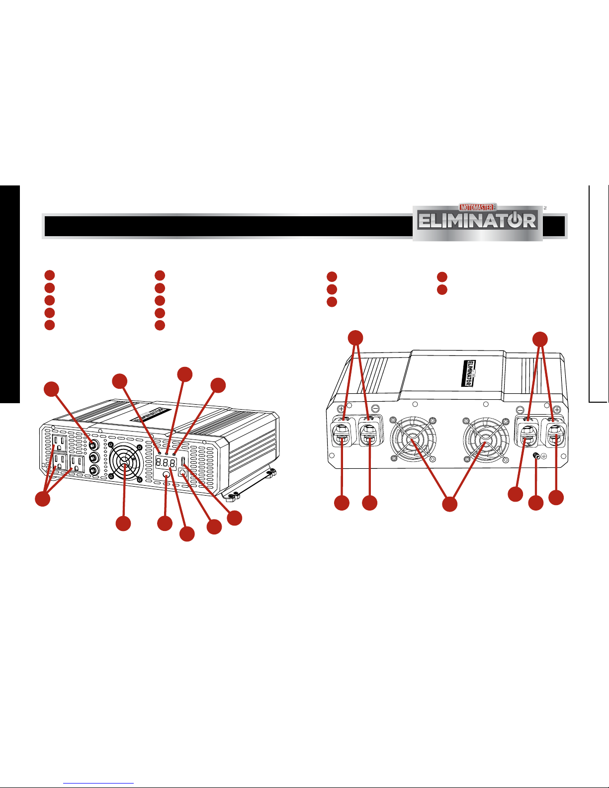
AC PANEL DC PANEL
111
212
313
4
5
614
715
8
9
10
USB port Positive DC terminals
Remote switch port Ground terminal
Digital display Negative DC terminals
Power switch button
Cooling fan and
ventilation opening
AC Outlets Cooling fan and ventilation openings
AC Outlet overload reset circuit Terminal covers
Input indicator (V)
Output power indicator (kW)
Output power indicator (W)
MM-111 846-01
POWER/
PUISSANCE
INPUT//ENTRÉE
(V)
OUTPUT/SORTIE
(KW) (W)
REMOTE ON/OFF
INTERRUPTEUR TÉLÉCOMMANDE
USB
3000 W
Digital Power Inverter
Onduleur Portatif Numérique
011-1846-6
1
2
3
4
5
6
789
10
MM-111 846-02
3000 W
Digital Power Inverter
Onduleur Portatif Numérique
011-1846-6
1213
11
13 11
14
15
15
9
KEY PARTS LIST
KEY PARTS LIST

10
model no. 011-1846-6 | contact us 1-877-619-6321
GENERAL USE
The MotoMaster®3,000 Watt
Modified Sine Wave Digital Inverter
efficiently and reliably supplies 115
V/60 Hz AC power with 3000 W
continuous output power for large
single loads, intermittent loads, or
multiple smaller loads. The inverter
is designed to meet UL standard
and cETL certification. The high-
quality and mid-range inverter is
suitable for charging or powering
electrical devices such as jacklight,
TV set, audio/video system, and
tools with power consumption
less than 3000 W. It is ideal for
operating household appliances,
cars, trucks, RVs and boats.
CHARACTERISTICS OF
INVERTER
• The inverter is not waterproof.
• The inverter has high surge
capability and functions in
ambient temperatures of -10°C
to 40°C.
• The inverter’s low standby
power ensures less battery
discharge, even if it is kept ON
for few days. (Stand by time is
varied based on the capacity
of battery connected.) It is not
recommended to keep inverter
always on, even when it is not
in use.
• The inverter has convenient USB
port. It powers most modern
electronic products.
SAFETY FEATURES
AC OUTPUT OVERLOAD OR
SHORT CIRCUIT SHUTDOWN -
This feature automatically turns
OFF the inverter if a short circuit
occurs or if the load attached to
the inverter exceeds the operating
limit. The digital display will show
“OLP” or “OPP” and the audible
alarm is also activated.
HIGH BATTERY VOLTAGE
SHUTDOWN - This feature
automatically shuts down the
inverter if the input voltage exceeds
15.5 +/- 0.5 V. The digital display
will show “OUP” and the audible
alarm is also activated. The inverter
recovers automatically when the
battery voltage drops to a safe
range.
LOW BATTERY VOLTAGE ALARM
- The alarm produces an audible
sound if the battery discharges to
11.0 +/- 0.3 V. The digital display
will show “LUP”.
LOW BATTERY VOLTAGE
SHUTDOWN - This feature
automatically shuts down the
inverter if the battery voltage
drops to 10.5 +/- 0.3 V. The digital
display will show “LUP” to prevent
the battery from being completely
discharged. The inverter recovers
automatically when the battery
voltage is 12 +/- 0.3 V DC.
OVER TEMPERATURE
SHUTDOWN - This feature
automatically turns OFF the
inverter if the internal components
temperature becomes too high.
The audible alarm produces a beep
when this happens. The digital
display will show “OCP”. This
may be caused by the ambient
temperature being too high (over
40°C) or bad ventilation.
MAIN FEATURES OF AC
PANEL
USB PORT - The port powers
and charges USB-enabled devices.
REMOTE SWITCH PORT - The
port through which the remote
control is connected using a
communication cable.
DIGITAL DISPLAY - This
display shows input voltage
in volts, output power in kilowatts
or watts under normal operating
conditions. It displays error code
under error or alarm conditions. The
allowed power tolerence is 15% for
loads of over 300 W. The allowed
voltage tolerance is
± 0.3 V under no load conditions.
POWER SWITCH BUTTON - This
button turns ON/OFF the
inverter.
COOLING FAN AND
VENTILATION OPENING - This
feature protects the inverter
from overheating. The ventilation
openings should be kept clear.
AC OUTLET - The inverter is
provided with three AC outlets
into which 115 V AC electrical
appliance having a power
consumption of 1500 W or less can
be plugged in.
INPUT INDICATOR (V) - This
indicator indicates that the
inverter is turned ON. The digital
display shows DC input voltage.
IMPORTANT INFORMATION
11
IMPORTANT INFORMATION
1
2
3
4
5
6
8

12
13
model no. 011-1846-6 | contact us 1-877-619-6321
OUTPUT POWER INDICATOR
(kW) - This indicator indicates
that the load consumption is 1000
W or above. The digital display
shows output power in kilowatts.
When AC output power is within
3100 W-3400 W, the AC output
overload shutdown feature turns
OFF the inverter.
OUTPUT POWER INDICATOR (W)
- This indicator indicates that
the load consumption is less than
1000 W. The digital display shows
output power in watts.
MAIN FEATURES OF DC
PANEL
POSITIVE DC TERMINALS -
These terminals accept ring
connectors of the positive cables
connected to the battery.
GROUND TERMINAL - This
terminal accepts a ground wire
which is connected to a ground.
NEGATIVE DC TERMINALS -
These terminals accept ring
connectors of the negative cables
connected to the battery.
COOLING FAN AND
VENTILATION OPENING - This
feature protects the inverter
from overheating. The ventilation
openings should be kept clear.
TERMINAL COVERS - These
covers are plastic covers to
prevent positive and negative DC
terminals from short circuit if the
bolt and nut are loosened.
INVERTER LOADS
The inverter will operate AC loads
within its power rating of 3,000
W. However, some appliances
and equipment may be difficult to
operate, and some appliances may
be damaged while operating them
with this inverter.
HIGH SURGE LOADS
Some induction motors used in
freezers, pumps, and other motor
operated equipment need high
surge current to start. This Inverter
may not be able to start these
motors even though their rated
current is within the inverter’s
limits. Observe the voltage reading
in digital display during motor
start up.
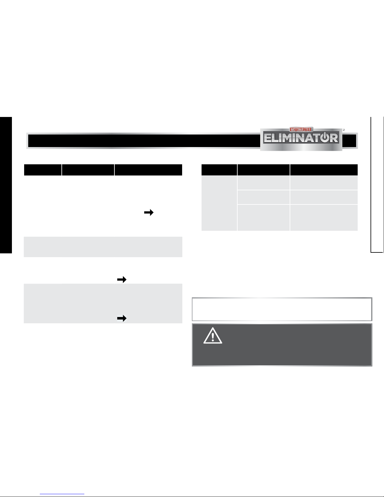
CONDITION DIGITAL DISPLAY DESCRIPTION
Left indicator on 13.5 Power supply: 13.5 Volts
Middle indicator on 1 Load consumption: 1 kW (1000 W)
Right indicator on 500 Load consumption: 0.5 kW (500 W)
LUP Low voltage alarm
LUP Under voltage shutdown
OUP Over voltage shutdown
OLP Over load shutdown
OCP Over temperature shutdown
OPP Short circuit
• If the reading drops below 11 V
while the inverter is starting the
motor, make sure all connections
are securely fastened, battery is
fully charged and proper sized
cables are used.
OPERATING LIMITS
The inverter delivers power to the load based on input voltage and ambient
temperature. The inverter will deliver more than 100 % of its continuous power
rating for approximately 5 minutes. Allow the inverter to cool for 15 minutes
before resuming operation above continuous power rating.
• Use a high capacity battery, if
the voltage still drops below
11 V even after rectifying the
problem.
IMPORTANT INFORMATION
IMPORTANT INFORMATION
914
15
10
11
12
13
INDICATORS AND DIGITAL DISPLAY CODES

14
15
model no. 011-1846-6 | contact us 1-877-619-6321
INPUT VOLTAGE
The table below depicts the input voltage limits under various operating
conditions.
OPERATING
CONDITION
VOLTAGE RANGE DESCRIPTION
Normal 11 V - 14 V
Peak
performance
13 V -14 V
Low voltage alarm 11.0 ± 0.3 V The audible low battery voltage alarm
sounds. The display will show “LUP”.
Low voltage
shutdown
10.5 ± 0.3 V The inverter shuts down to protect the
battery from being over-discharged. The
display will show “LUP”.
High voltage
shutdown
15.5 ± 0.5 V The inverter shuts down to protect itself
from excessive input voltage. The display
will show “OUP”
NOTE: Even though the inverter has
over-voltage protection feature, it can be
damaged if input voltage exceeds 16 V.
Inverter restarts
after low voltage
shutdown
12.0 ± 0.3 V The inverter will not restart unless the
battery voltage is suitable for operating
the load.
LOAD PERFORMANCE CHART FOR THE 3,000 WATT
MODIFIED SINE WAVE DIGITAL POWER INVERTER
011-1846-6
This power inverter is modified sine wave inverter, it will perform good for most
of the appliances. Please refer to below table for applications performance
rating comparison of modified sine wave inverter and pure sine wave inverter.
APPLICATIONS PERFORMANCE RATING
MODIFIED SINE WAVE
INVERTER
PURE SINE WAVE
INVERTER
LCD/Plasma TV — * * *
Standard TV * * * * *
Audio equipment * * * *
Laptop * * * * * *
Desktop computer * * * * *
Microwave * * * * *
Table saw/ Air compressor * * * * *
Hand power tool * * * * *
Coffee maker, toaster, hair dryer * * * * * *
Blender, mixer, coffee grinder * * * * *
Laser printer — * * *
IMPORTANT INFORMATION
IMPORTANT INFORMATION

16
17
model no. 011-1846-6 | contact us 1-877-619-6321
APPLICATIONS PERFORMANCE RATING
MODIFIED SINE WAVE
INVERTER
PURE SINE WAVE
INVERTER
Photo copier — * * *
Bubble jet printer * * * * *
Fax machine * * * * *
Air conditioner * * * *
Light (incandescent) * * * * * *
Light (others) * * * * *
Medical equipment — * * *
— Not recommended * * Good performance
*Adequate performance * * * Ideal performance
LOAD RUN TIME SPECIFICATION
LOAD RUN TIME PER BATTERY TYPE
APPLIANCE WATT 22 NF (100
AH)
8 D (200) DUAL
8Ds
(400 AH)
6 V GOLF
CART
(440 AH)
FOUR 8DS
(800 AH)
19" Color
TV 100 8 h 19 h 44 h 49 h 100 h
Computer 200 3 h 30 min 8 h 19 h 21 h 44 h
Power drill 500 1 h 10 min 2 h
40 min 6 h 7 h 14 h
30 min
Coffee
maker 1000 30 min 1 h
10 min
2 h
30 min 3 h 6 h
Microwave
oven 1500 – 40 min 1 h
30 min
1 h
45 min 4 h
Coffee
maker
and
Microwave
oven
2500 – – 1 h 1 h 2 h
— Not recommended
IMPORTANT INFORMATION
IMPORTANT INFORMATION

19
model no. 011-1846-6 | contact us 1-877-619-6321
PACKAGING CONTENTS
NO. MATERIAL NAME QUANTITY ILLUSTRATION
1Digital Power
Inverter 1
26 m wired remote
control 1
3 Owner’s manual 1
POWER/
PUISSANCE
INPUT//ENTRÉE
(V)
OUTPUT/SORTIE
(KW) (W)
REMOTEON/OFF
INTERRUPTEURTÉLÉCOMMANDE
USB
3000 W
DigitalPowerInverter
OnduleurPortatif Numérique
011-1846-6
NOTE:
If any of these materials are missing or damaged, please contact our TOLL-FREE
HELPLINE: 1-877-619-6321.
BEFORE INSTALLATION
Follow all instructions including safety guidelines mentioned in this manual.
DETERMINING BATTERY CAPACITY
• Determine the battery capacity based on the type and requirement of load.
Please use with 12 V battery only.
• Battery type and size strongly affect the performance of the inverter.
DETERMINING CHARGING SYSTEM
• Choose an appropriate charging system. A well-designed charging system
allows the battery to remain in optimal condition, thereby supplying power
when needed.
• Inadequate charging and wrong charger type will affect the system
performance and reduce battery life.
WARNING!
Please consult a qualified professional for installing electrical
equipment. Only qualified professionals have knowledge of
applicable installation codes and the hazards involved in performing
electrical work.
CAUTION! EQUIPMENT DAMAGE
The inverter will not operate if connected to a 6 V battery and will be
damaged if connected to a 24 V battery.
18
IMPORTANT INFORMATION
ASSEMBLY INSTRUCTION
20
21
model no. 011-1846-6 | contact us 1-877-619-6321
CHOOSING A LOCATION
The inverter contains components that tend to produce arcs or sparks. It is not
recommended to use this device for marine applications.
The inverter should be operated only in locations that meet the following
requirements:
WARNING!
• To prevent fire or explosion, do not install the inverter in
compartments containing batteries, flammable materials, or
ignition-protected equipment.
• Do not cover or obstruct the ventilation openings of the inverter.
• Never install the inverter in a zero-clearance environment, as
doing so may cause overheating of the inverter.
CONDITION DESCRIPTION
Dry Avoid splashing of water or other liquids on the inverter.
Cool Maintain the ambient air temperature between 14°F and 104°F
(-10°C and 40°C).
Ventilated Leave at least 3” (7.5 cm) of space around the inverter for airflow.
Ensure that the ventilation openings are not obstructed.
Safe Do not install the inverter in a compartment containing batteries or
flammable liquids like gasoline.
Close to battery Do not use an excessively longer DC cable, as it increases wire
resistance and reduces input power.
Protection from
battery gases
Do not mount the inverter in a place where it is exposed to gases
produced by the batteries. Prolonged exposure to these gases will
damage the inverter, as they are very corrosive.
Clean Do not operate the inverter in an area that is prone to dirt, dust or
debris.
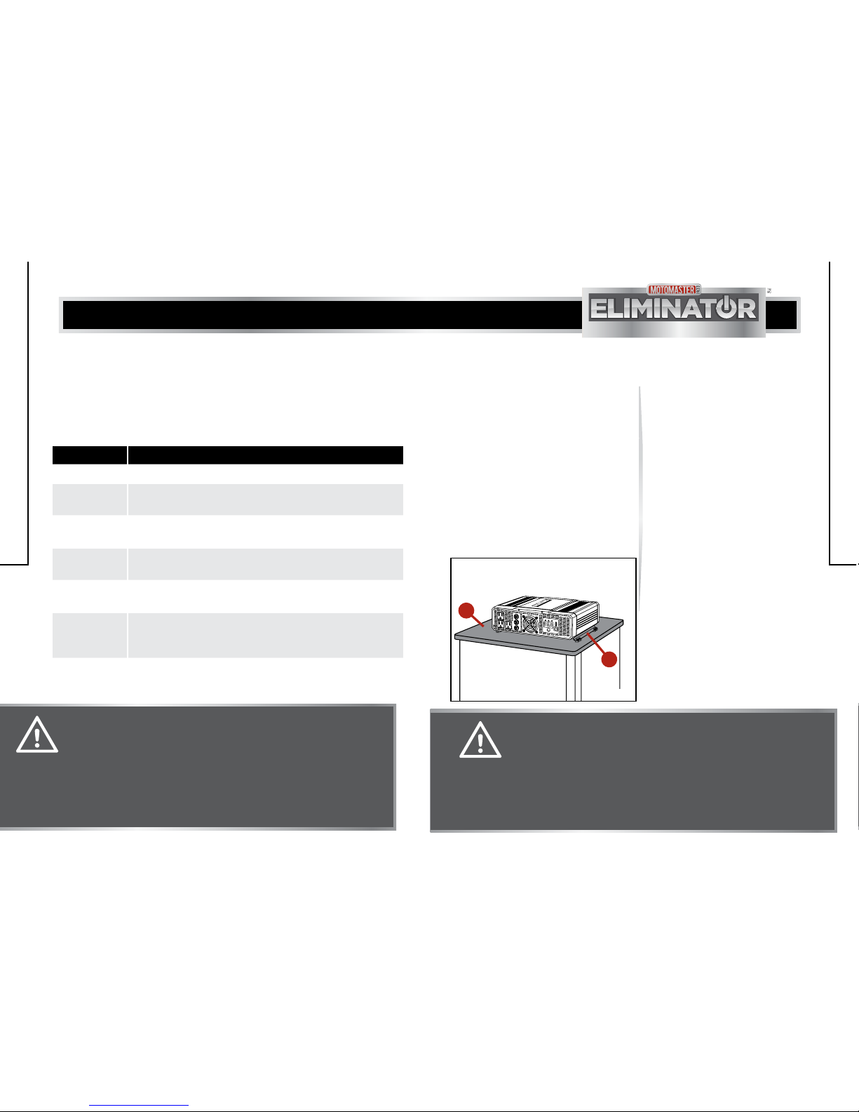
MOUNTING THE INVERTER
1. Place the inverter in a suitable
location and orientation. The
inverter can be positioned on a
vertical or horizontal surface. Make
sure the inverter DC connections
must point left/right while
installing on vertical surface.
2. Hold the inverter against the
mounting surface (1) and mark
the positions on the surface with
respect to mounting bracket (2)
(fig A).
3. Drill four mounting holes on the
marked position of the surface.
4. Align the holes on the mounting
surface with corresponding
holes of the mounting bracket.
Fasten the inverter on the
mounting surface using
corrosion-resistant fasteners.
It is recommended to use
M6 fasteners for mounting
purpose.
fig A
POWER/
PUISSANCE
INPUT//ENTRÉE
(V)
OUTPUT/SORTIE
(KW) (W)
REMOTEON/OFF
INTERRUPTEURTÉLÉCOMMANDE
USB
3000 W
DigitalPower Inverter
OnduleurPortatif Numérique
011-1846-6
MM-111846-03
1
2
CAUTION! EQUIPMENT DAMAGE
• Do not install the inverter in a wet environment or in any
environment where the moisture can enter through the
ventilation openings.
• If the inverter is mounted vertically, the DC connections should
not point up or down to avoid foreign material from falling or
settling into the unit.
ASSEMBLY INSTRUCTION
ASSEMBLY INSTRUCTION
22
23
model no. 011-1846-6 | contact us 1-877-619-6321
CONNECTING THE BATTERY CABLES
1. Make sure the inverter is turned
OFF.
2. Prepare the 2 sets of positive and
negative cables to connect to
battery (2 positive cables and
2 negative cables. Total 4 cables).
Copper cable with 2 ring terminals
are recommended (ring terminals
at inverter side should be with
10 mm diameter hole, and other
other side should be the same size
as the battery terminal connection).
It is highly recommended to
use red cables for positive
terminal and black cables for
the negative terminal. Refer to
this chart for the copper cables
gauge depending on distance.
CABLE LENGTH CABLE GAUGE
<=3' 4 AWG (4 cables)
<=6' 2 AWG (4 cables)
<=10' 1 AWG (4 cables)
WARNING!
• It is strongly recommended to contact a qualified professional.
• Do not perform the cable connection if the environment has any
flammable fumes. Always ventilate the battery compartment
before making this connection. If not explosion or fire may occur.
• Always make sure the cable connection is tight. Loose
connections may cause excessive voltage drop, thereby leading
to overheating and melting of cable insulation.
• Please connect 4 cables with all 4 DC terminals according to
the assembly instructions in this manual. Failure to do so may
damage the inverter.
NOTE
The Digital Power Inverter uses low-voltage and high-current input, hence low-resistance
wiring between the battery and the inverter is essential to deliver the maximum amount of
usable energy to the load.
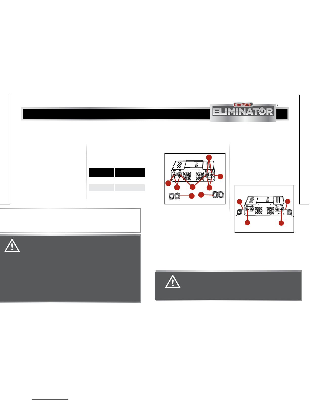
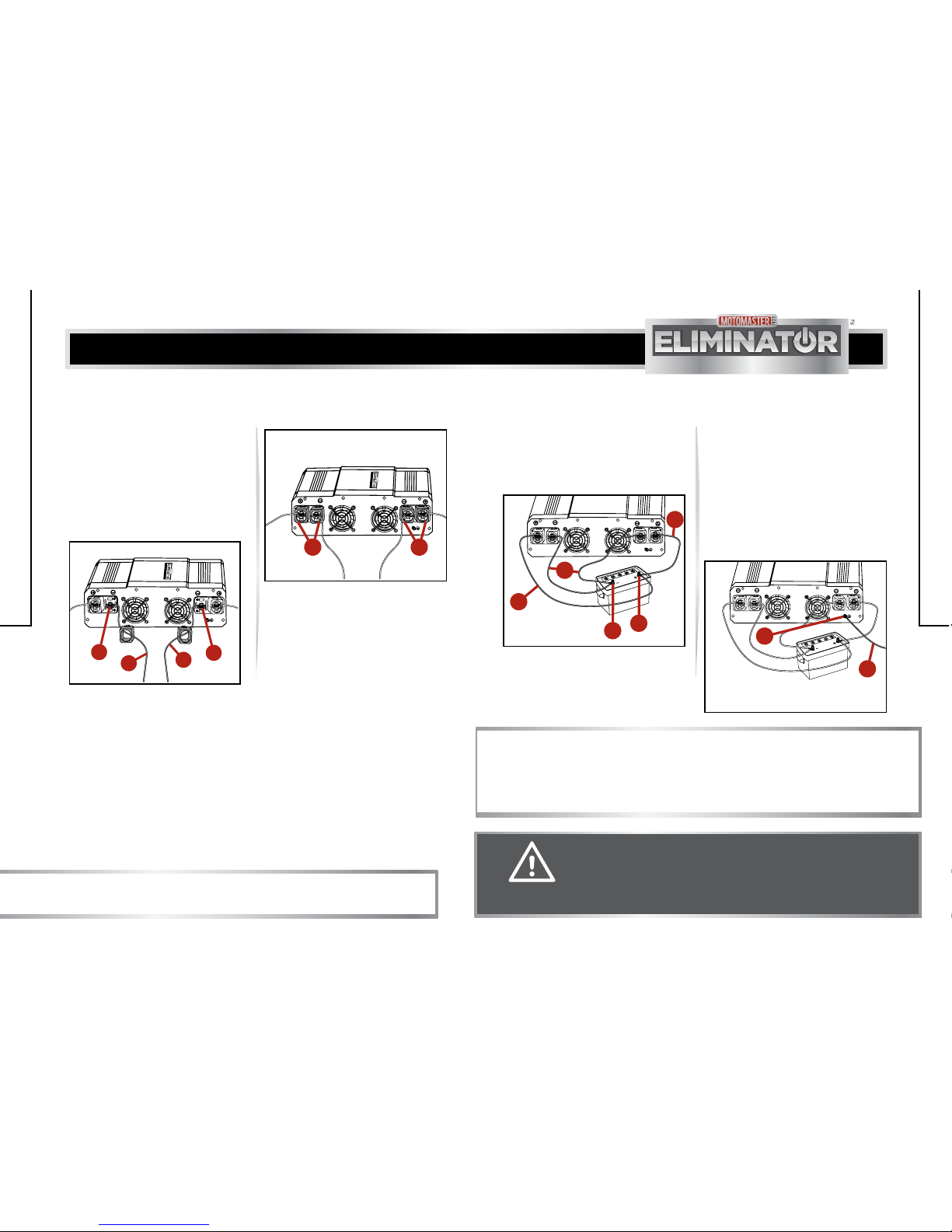
3. Remove the terminal covers (1),
nuts (2), washers (3) and bolts (4)
from the positive and negative DC
terminals (fig B).
4. With the positive (red) battery
cable (1) passing through the
terminal cover, connect the
ring connector on one end of
the positive battery cable to
the positive (red) DC terminal
(2) of the inverter. Make sure
both positive DC terminals
are connected with the cables
(fig C).
CAUTION! EQUIPMENT DAMAGE
Do not change the negative and positive polarities of battery
cable, while connecting into the DC terminals. A reversed polarity
connection will damage the inverter, thereby voiding the warranty.
ASSEMBLY INSTRUCTION
ASSEMBLY INSTRUCTION
MM-111 846-04
fig B
3000 W
DigitalPower Inverter
OnduleurPortatif Numérique
011-1846-6
3
2
4
43
1
1
3
MM-111846-05
fig C
3000 W
DigitalPower Inverter
OnduleurPortatif Numérique
011-1846-6
2
2
1
1
24
25
model no. 011-1846-6 | contact us 1-877-619-6321
5. With the negative (black) battery
cable (1) passing through the
terminal cover, connect the ring
connector on one end of the
negative battery cable to the
negative (black) DC terminal
(2) of the inverter. Make sure
both negative DC terminals are
connected with the cables (fig D).
6. Insert the nuts on all 4 DC
terminals and tighten them with
washers. Do not overtighten.
8. Connect the ring connectors on
the other ends of both negative
(black) battery cables (1) to the
negative (black) terminal (2) of
the battery (fig F). Tighten the
nut with washer firmly. Do not
overtighten.
7. Insert both terminal covers (1)
back onto the inverter (fig E).
MM-111846-06A
fig E
3000 W
DigitalPower Inverter
OnduleurPortatif Numérique
011-1846-6
11
NOTE:
Spark may occur during the cable connection. This is normal condition.
ASSEMBLY INSTRUCTION
ASSEMBLY INSTRUCTION
CAUTION! EQUIPMENT DAMAGE
Do not change the negative and positive polarities of battery
cable, while connecting into the DC terminals. A reversed polarity
connection will damage the inverter, thereby voiding the warranty.
NOTE:
If connecting the inverter in a vehicle, connect the copper wire to the chassis of the
vehicle. If connecting the inverter in a boat, connect the copper wire to the boat grounding
system. If connecting the inverter in a fixed location, connect the copper wire to a ground
rod (a metal rod pounded into the earth) or other proper service entrance ground.
9. Connect the ring connectors on the
other ends of both positive (red)
battery cables (3) to the positive
(red) terminal (4) of the battery
(fig F). Tighten the nut with washer
firmly. Do not overtighten.
10. Prepare a 14 AWG copper
wire (1) with enough length
to connect the inverter to a
ground. Strip the insulation at
both sides. Connect one end of
the copper wire to the ground
terminal (2) of the inverter, and
the other end of the wire to the
ground (fig G).
MM-111846-07
fig F
4
2
1
3
3
MM-111846-07A
fig G
1
2
MM-111846-06
fig D
3000 W
DigitalPower Inverter
OnduleurPortatif Numérique
011-1846-6
2
2
1
1

26
model no. 011-1846-6 | contact us 1-877-619-6321
ASSEMBLY INSTRUCTION
11. Turn ON the inverter using power
switch button. Refer operating
instructions page 27, step 1.
12. Check the front panel of the
inverter. The digital display (1)
will indicate 12-13 V, depending
on the battery voltage. If there is
no indication, check the battery
and its connection to the inverter
(fig H).
MM-111846-08
fig H
POWER/
PUISSANCE
INPUT//ENTRÉE
(V)
OUTPUT/SORTIE
(KW) (W)
REMOTEON/OFF
INTERRUPTEURTÉLÉCOMMANDE
USB
3000 W
Digital Power Inverter
Onduleur Portatif Numérique
011-1846-6
1
27
OPERATION
TURNING ON/OFF THE INVERTER RESTARTING THE INVERTER
AFTER AC OUTPUT SHUTDOWN
1. Press the power switch button (1)
for half a second to turn ON the
inverter (fig I).
1. Press the power switch button for
one second to turn OFF the inverter.
2. Remove all AC loads from the
inverter. Allow the inverter to
cool down for 15 minutes.
3. Then, press the power switch
button for half a second to turn
ON the inverter.
2. Press the power switch button
for one second to turn OFF the
inverter.
MM-111846-09
fig I
POWER/
PUISSANCE
INPUT//ENTRÉE
(V)
OUTPUT/SORTIE
(KW) (W)
REMOTEON/OFF
INTERRUPTEURTÉLÉCOMMANDE
USB
011-1846-6
3000 W
Digital Power Inverter
Onduleur Portatif Numérique
1
WARNING!
Before working on any circuits connected to the inverter, always
disconnect DC and AC power source from the inverter even if the
ON/OFF switch is in OFF position.
NOTE:
• The inverter does not draw current from the battery, when the power switch button is
in OFF position.
• When the power switch button is in ON position and there is no power supply to
the load, the inverter draws less than 1 A from the battery. It would take a week to
discharge a 100 Ah battery with this low current. Therefore, there will not be excessive
discharge of the battery even if the inverter remains in ON condition for several days.
• Keep the inverter in OFF condition, if the battery has to be recharged within a week.

28
model no. 011-1846-6 | contact us 1-877-619-6321
OPERATING SEVERAL LOADS
CHARGING USB LOADS
1. Press the power switch button
for half a second to turn ON the
inverter.
2. While operating multiple loads,
turn ON the loads from high
capacity to low capacity. This will
avoid the inverter from delivering
the starting current for all the
loads simultaneously.
1. Use the USB port (1) for charging
and powering USB-powered
devices (2) such as portable music
(MP3) player, mobile phone, and
video game player (fig J).
MM-111846-10
fig J
POWER/
PUISSANCE
INPUT//ENTRÉE
(V)
OUTPUT/SORTIE
(KW) (W)
REMOTEON/OFF
INTERRUPTEURTÉLÉCOMMANDE
USB
3000 W
Digital Power Inverter
Onduleur Portatif Numérique
011-1846-6
1
2
CAUTION! EQUIPMENT DAMAGE
Do not charge portable GPS receivers and certain cameras using
this inverter, as these devices may not be compatible and damage
the inverter when plugged in.
OPERATION
MAINTENANCE
The inverter will operate efficiently when maintained properly.
• Clean the exterior surface of the inverter with a damp cloth to prevent
accumulation of dust and dirt.
• Ensure that the DC cables are secured and fasteners are tightened.
• Recharge the battery before it is discharged to 50%. This will extend
the durability and efficiency of the battery.
29
MAINTENANCE
1. Make sure the USB device
accepts 5 V and can be
charged using a USB power
source. Refer technical
specifications page 32.
2.
31
model no. 011-1846-6 | contact us 1-877-619-6321
PROBLEM POSSIBLE CAUSE SOLUTION
The digital display
shows “LUP”.
• Low battery voltage
shutdown feature turns
OFF the inverter.
• Recharge the battery. Check
if cables and connections are
secure.
• DC wiring is incorrect. • Use proper cable length and
gauge. Refer assembly
instructions page 22.
Make secure cable connections.
• Battery condition is
poor.
• Charge or replace the battery if
needed.
The digital display
shows “OUP”.
High battery voltage
shutdown feature turns OFF
the inverter.
Make sure the inverter is connected
to a 12 V battery.
The digital display
shows “OLP”.
AC output overload
shutdown feature turns OFF
the inverter.
Make sure the load attached to the
inverter is within the operating limit.
Refer technical specifications
page 32.
The digital display
shows “OCP”.
Over temperature
shutdown feature turns OFF
the inverter.
Make sure the inverter is placed in a
well-ventilated area and ventilation
openings are not obstructed. Reduce
the ambient temperature if possible.
Refer technical specifications
page 32.
The digital display
shows “OPP”.
Occurrence of short circuit. Check the AC wiring.
PROBLEM POSSIBLE CAUSE SOLUTION
No output voltage
and voltage
indication.
• The inverter is in OFF
position.
• Turn ON the inverter.
• There is no power
supply to the inverter.
• Check the wiring to the inverter.
• The DC polarity is
reversed.
• Reverse DC polarity will damage
the inverter and voiding the war-
ranty. Have a qualified service
technician to repair.
WARNING!
Do not disassemble the inverter, as it does not contain user-
serviceable parts.
Have the inverter serviced by a qualified technician. Attempting to
service the inverter by yourself could result in electric shock or burn.
TROUBLESHOOTING
NOTE:
For further assistance with the MotoMaster®Eliminator, contact customer
service at 1-877-619-6321.
TROUBLESHOOTING
30
TROUBLESHOOTING
32
33
model no. 011-1846-6 | contact us 1-877-619-6321
PHYSICAL SPECIFICATION
Ambient operating temperature
range
14°F - 104°F (-10°C - 40°C)
Dimension (L x W x H) 11 7/8 x 12 15/16 x 4 3/16”
(30.2 x 32.9 x 10.6 cm)
Weight 10 lb 8 oz (4.8 kg)
IMPORTANT:
All specifications are subject to change without notice.
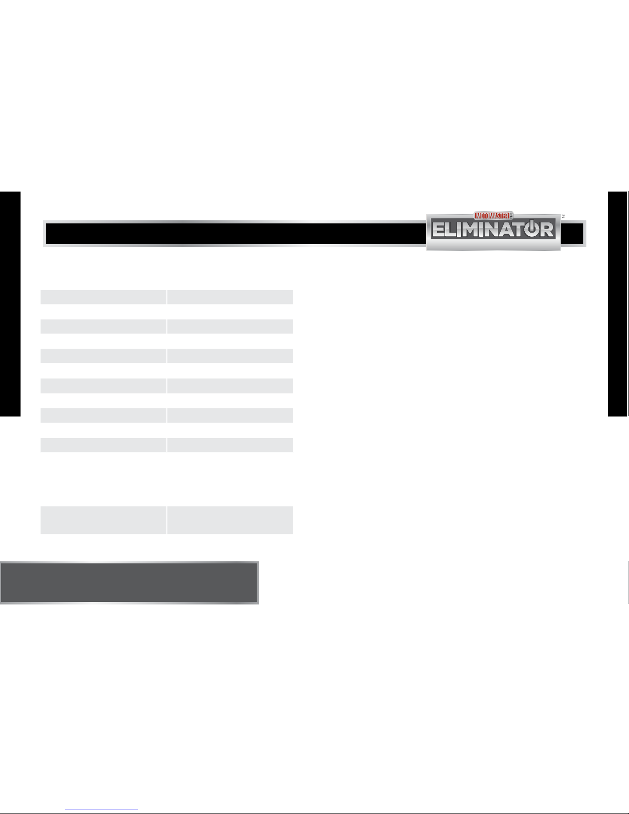
ELECTRICAL SPECIFICATION
Continuous AC output power 3000 W
Maximum AC output surge power 6000 W
AC output voltage range 104 V - 127 V AC
Output frequency (nominal) 60 ± 1 HZ
Output waveform Modified sine wave
DC output 5 V DC, 2100 mA
DC input voltage range 11 V - 14 V DC
Low battery alarm Audible, 11 ± 0.3 V DC
Low battery shutdown 10.5 ± 0.3 V DC
Low battery shutdown resume 12.0 ± 0.3 V
High battery shutdown 15.5 ± 0.5 V
Fuse (replaceable) 25 A fuse x 16
TECHNICAL SPECIFICATION
WARRANTY
This MotoMaster®Eliminator product carries a two (2) year limited warranty
against defects in workmanship and materials. At its discretion, MotoMaster
Canada agrees to have any defective part(s) repaired or replaced free of
charge, within the stated warranty period, when returned by the original
purchaser with proof of purchase. This product is not guaranteed against wear
or breakage due to misuse and/ or abuse.
Imported by MotoMaster®Canada, Toronto, Canada M4S 2B8.
Table of contents
Other Eliminator Inverter manuals


Popular Inverter manuals by other brands


Robur
Robur B15 Generators Series Installation, user and maintenance manual

Phocos
Phocos Any-Grid Series User and installation manual

Daikin
Daikin E Series Service manual

Black Max
Black Max BMi2100 Series Operator's manual

Samsung
Samsung ELSR362-00004 installation manual

NewMar
NewMar 48-1U-1000RM user manual

opti-solar
opti-solar SP 5000 Vitality-S operating manual

Kuhne electronic
Kuhne electronic MKU 57 G4 manual

SMA
SMA SUNNY TRIPOWER CORE1-JP manual

Darfon
Darfon PVI5000 Installation and operating manual

SolarEdge
SolarEdge Dry-Contact switch installation guide

Advanced Energy
Advanced Energy AE 600 user manual