INSTALLATION INSTRUCTIONS FOR RAIL MOUNTED REGENERATIVE DRYERS
INSTALLATION INSTRUCTIONS -BYPASS CIRCUITINSTALL
IMPORTANT: Tsunami Regenerative Dryers are configurable in multiple
variations. Before beginning installation it is important to determine the
direction of air flow which best meets your installation application
requirements.
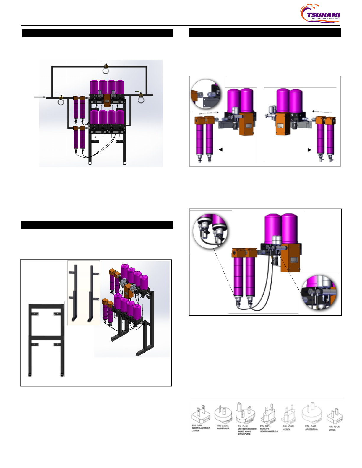
For ease of service, it is highly recommendedto install a bypass
circuit around the regenerative dryer. Followthe diagram below
when installing a bypass circuit. Verify that system pressure is relieved
prior to preforming installation.
Air Supply
A
A. Inlet Ball Valve B. Bypass Ball Valve C. Outlet Ball Valve
Using the Dryer: Open the inlet (A) and outlet (C) ball valves andclose the
Bypass (B) ball valve to direct air flowthrough the regenerative dryer. This
will provide clean, dry airdownstream.
Bypassing theDryer: Close the inlet (A) and outlet (C) ball valves andopen the
Bypass (B) ball valve to direct airflowaround the dryer. This will allowservice or
maintenance to be preformed without shuttingdown total compressed air
supply.
INSTALLATION INSTRUCTIONS -DRYER INSTALLTION
1. Remove all system pressure.
2. Remove hardware from frame. Install cross members withbolt and
lock washer. Square up rack using level or square. Tighten with 9/16”
socket.
3. Using the appropriate hardware (not included), mount dryer bracket to
wall. Figure 1. Can beconfigured with brackets on insideor outsideof
rack. Securing to floor is optional if dryer is also secured to wall.
4. Once the wall bracket has been properly secured to the wall, placethe
dryer mountingrail into the slot(s) of the wall bracket. Figure 1
Figure 1
INSTALLATION INSTRUCTIONS -DRYER INSTALLTION cont.
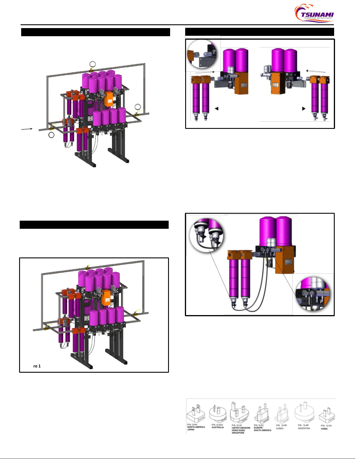
4. Using an adjustable or 1-3/8” wrench, connect thesupplied FEMALE
JIC fitting to the outlet port of the Tsunami pre-filter assembly. Use
appropriate thread sealant. Figure 2
5. Determine preferred direction of flow.
6. Using the appropriatethread sealant, install theMALE JIC connector
to eitherthe left or right INLET / AUXport of the dryer. Figure 2
Flow: L to RFlow: R to L
Figure 2
7. Using an adjustable or 5/8” wrench, plug the remaining open ports
with the provided 1”port plugs and large hextool. Useappropriate
thread sealant.
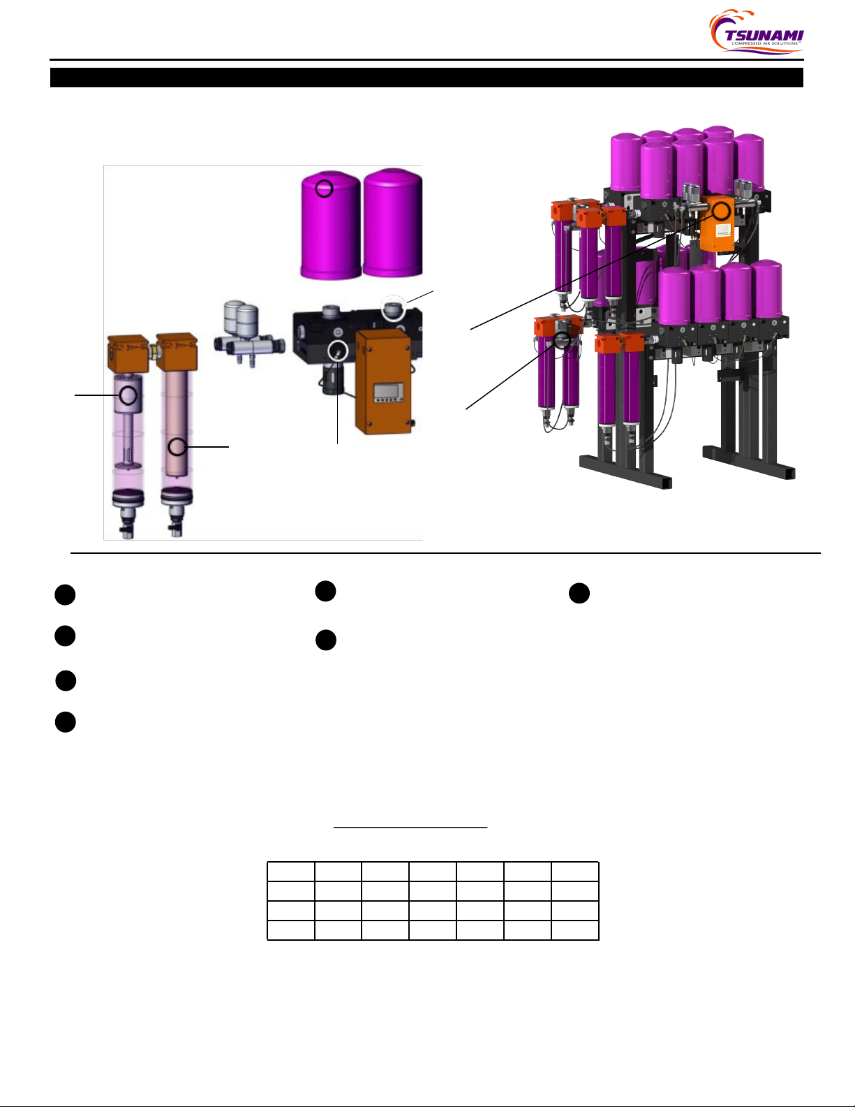
8. Attached the filter assembly to the dryer housing by connecting the
MALE and FEMALE JIC fittings. Tighten firmly.
9. Use the provided ¼” black nylon tubing to connect the Moisture Minder®
Piston Drains to the strainers located on the bottom of each filter
housing. Excess tubingcanbe trimmed to length. Figure 3
Figure 3
10. Attach 3/8”clear plastic tubingto the bottom of theMoisture Minder®
PistonDrains. Followall localandstateregulations when routing the drain
lines.
11. a. Connect power. Plug in wall pack adaptor to the PLC Control Box.
Make sure to snugup the lock nut locatedon the PLC endof the
power supply and then plug wall pack into 120v outlet
b. For 24v dryers, plug cord barrel into PLC then connect to power
source; be certain to properly terminate the positive and negative
wires for the correct polarity.
B
C
Date Printed 1/31/2023 764-2095 Rail Mounted Dryer Instructions 2
** Note: For international dryer installations, outside of North America,
choose the correct prong adaptor for the region prior to plugging into any
power outlet. Reference chart below for your specific prong requirement.