Tsunami 21999-1105 User manual

Date Printed: 5/3/2021 INST-Pure 5 Regenerative Dryer Series
USER MANUAL
THE FOLLOWING USER MANUAL APPLIES TO TSUNAMI PURE 5 REGENERATIVE DRYERS
WARNING
Your safety is very important. Read all instructions before beginning any
service or installation on your Tsunami Regenerative Dryer. Always wear
safety eye protection when working with compressed air products.
Failure to follow maintenance instructions could result in operating
failure or product damage. System pressure must be released prior to
any installation or service. Always install the system with the arrows
indicating the direction of airflow. Use appropriate thread sealant on all
connection fittings unless otherwise specified. Do not alter the filtration
system from its original design as this may cause failure in its operation
parameters.
DRYER SPECIFICATIONS
Maximum Inlet Air Temperature: 150°F
Maximum Pressure: 175 psi
Maximum Flow: 17 SCFM
Inlet Port: 1/4” NPT
Outlet Port: 1/2” NPT
INSTALLATION & SERVICE REQUIREMENTS
pg. 3
pg. 3
IMPORTANT: Tsunami Regenerative Dryers are configurable in multiple
variations. Before beginning installation it is important to determine the
direction of air flow which best meets your installation application
requirements. Failure to follow mandatory maintenance schedule will void
warranty.
Dryer Installation & Configuration
Mandatory6 Month Service
•Oil CoalescingFilter Element Replacement (P/N: 21999-0394)
Recommended 6 Month Service
•Lubrication of pistonspooland piston bore
Recommended Annual Service
•Replacement of pistonspool and pistonbore (P/N: 21999-0707)
Recommended 3 Year Service
•Replacement of dryer canisters (P/N: 21999-0976)
Troubleshooting Guide
DESCRIPTION
Congratulations on the purchase of your Tsunami Regenerative Drying
System! By adhering to the specifications and maintenance schedule
listed in the manual, your air system will provide years of service with
minimal maintenance.
Incoming air enters the 1st stage water separator where water and
particulates are removed down to 10 micron. The air then travels
through the 2nd stage oil coalescing filter where oil aerosols are filtered
down to .001 ppm and particulates are trapped down to .01 micron. The
pretreated air enters the regenerative dryer where molecular sieve
desiccant captures water vapor. Approximately every 90 seconds, the
timer sends out a signal causing an internal piston to shift. The shift in
the piston redirects air flow through the opposite dryer canister. This
Tsunami Regenerative Drying System can provide dew points down to
–80°F and relative humidity down to .01% RH. All dryers come standard
with automatic drains to assume proper disposal of all contaminates
captured in the water separator and oil coalescing filter.
T
User Manual:
sunami Regenerative Dryers
5 HP DualTower Regenerative Dryer
PN: 21999-1105
pg. 3
pg. 4
pg. 2
pg. 4
5 HP DualTower Regenerative Dryer
PN: 21999-1105-MM

Date Printed: 5/3/2021 2 INST-Pure 5 Regenerative Dryer Series
USER MANUAL Pure 5 Regenerative Dryer Series
INSTALLATION INSTRUCTIONS -BYPASS CIRCUITINSTALL
IMPORTANT: Tsunami Regenerative Dryers are configurable in multiple
variations. Before beginning installation it is important to determine the
direction of air flow which best meets your installation application
requirements.
All dryers contained in this manual follow the same installation
procedures.
For ease of service, it is highly recommended to install a bypass circuit
around the regenerative dryer. Follow the diagram below when installing a
bypass circuit. Verify that system pressure is relieved prior to performing
installation.
Air Supply
A
B
C
A. Inlet Ball Valve B. Bypass Ball Valve C. Outlet Ball Valve
Using the dryer: Open the inlet and outlet ball valves and close the
bypass valve to direct air flow through the regenerative dryer. This will
provide clean, dry air downstream.
Bypassing the dryer: Close the inlet and outlet ball valves and open the
bypass valve to direct airflow around the dryer. This will allow service or
maintenance to be preformed without shutting down total compressed
air supply.
INSTALLATION INSTRUCTIONS -DRYER INSTALLTION
1. Remove all system pressure.
2. Using the appropriate hardware (not included), mount dryer bracket to
wall. Figure 1
3. Once the wall bracket has been properly secured to the wall, place the
dryer mounting rail into the slot(s) of the wall bracket. Figure 1
Figure1
INSTALLATION INSTRUCTIONS -DRYER INSTALLTION cont.
4. Install the supplied FEMALE JIC fitting to outlet port of the Tsunami pre-
filter assembly. Use appropriate thread sealant. Figure 2
5. Determine preferred direction of flow. IMPORTANT: Air must travel
through the Tsunami filters prior to entering the regenerative dryer.
6. Using the appropriate thread sealant, install the MALE JIC connector to
either the left or right INLET / AUX port of the dryer. Figure 2
Flow: L to RFlow: R to L
Figure2
7. Using an adjustable or 5/8” wrench, plug the remaining open ports
with the provided 1” port plugs and large hex tool. Use appropriate
thread sealant.
8. Attach the filter assembly to the dryer housing by connecting the
MALE and FEMALE JIC fittings. Tighten firmly.
9. (21999-1105-MM MODELS ONLY) Use provided black nylon tubing to
connect Moisture Minder® Filter Drains to “T” fitting located on dryer
housing. Excess tubing can be cut to length. Figure 3
Figure3
10. Attach 3/8” clear plastic tubing to the bottom of the Float Drains or
Moisture Minder® Filter Drains. Follow all local and state regulations
when routing the drain lines.
11. For 110v dryers, plug unit into wall.
12. For 220v dryers, install a 220/230/240 single phase plug on flying
leads and plug into appropriate outlet or hardwire into gauge box.
Make sure all local electrical codes are followed and that work is
performed by a qualified representative.

Date Printed: 5/3/2021 3 INST-Pure 5 Regenerative Dryer Series
INSTALLATION INSTRUCTIONS -Install Tank
Install tank using universal mounting straps. Wrap straps around front of
tank and secure on back side of tank. Using 5/16” cap screws, affix straps
to wall bracket. Tighten bands on tank using 1/4x3” cap screws.
INSTALLATION INSTRUCTIONS -DRYER INSTALLTION
INSTALLATION INSTRUCTIONS -DRYER INSTALLTION cont.
Attach 3/8” clear plastic tubing to the bottom of the Float Drains or Moisture
Minder® Filter Drains. Follow all local and state regulations when routing the
drain lines.
For 110v dryers, plug unit into wall.
For 220v dryers, install a 220/230/240 single phase plug on flying leads and
plug into appropriate outlet or hardwire into gauge box. Make sure all local
electrical codes are followed and that work is performed by a qualified
representative.
Side view of mounting straps and wall
bracket.
Install tubing from dryer to tank using push to
connect fittings.
IMPORTANT: Tsunami Regenerative Dryers are configurable in
multiple variations. Before beginning installation it is important to
determine the direction of air flow which best meets your installation
application requirements.
All dryers contained in this manual follow the same installation
procedures.
21999-1105-T-MM
21999-1105-T
USER MANUAL Pure 5 Regenerative Dryer Series

Date Printed: 5/3/2021 4 INST-Pure 5 Regenerative Dryer Series
USER MANUAL Pure 5 Regenerative Dryer Series
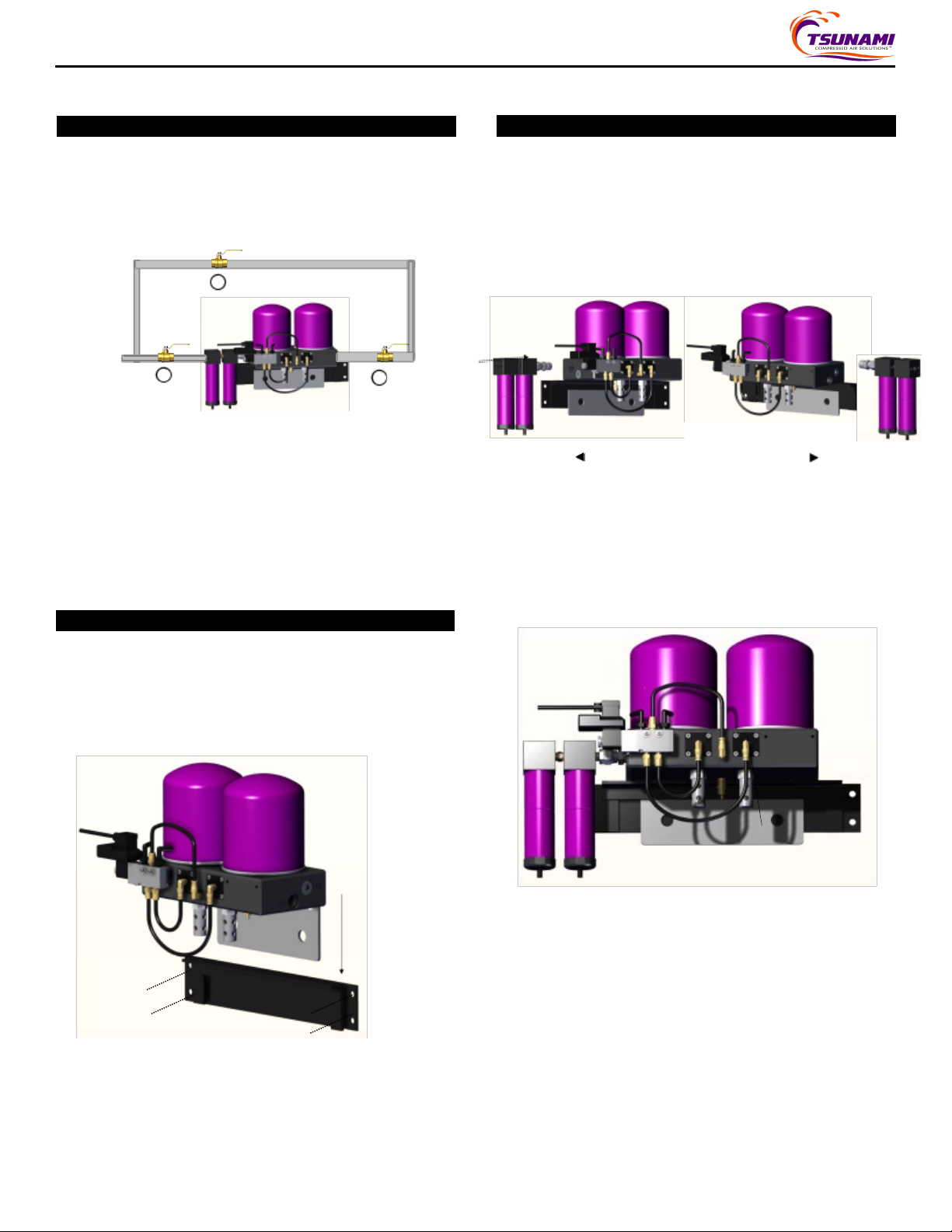
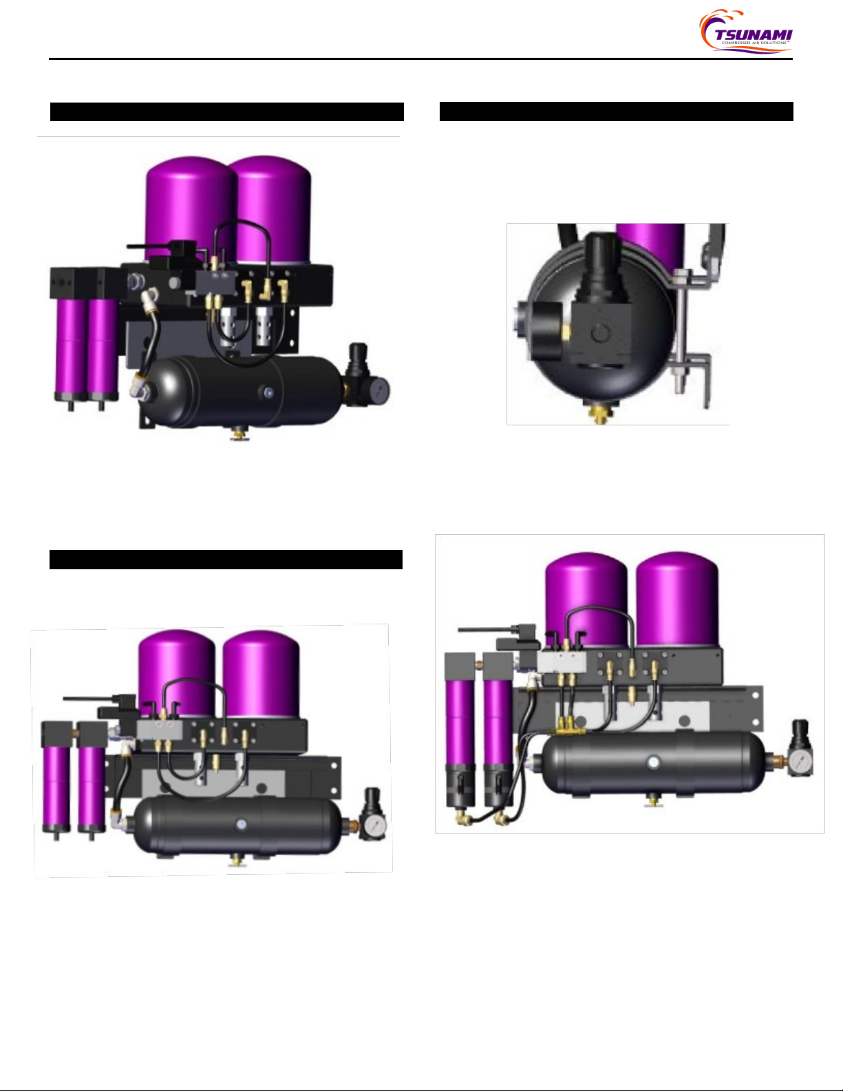
MAINTENANCE INSTRUCTIONS -COALESCING ELEMENT MAINTENANCE INSTRUCTIONS -PISTON LUBRICATION
Recommended every6 months
•Lubrication of pistonspooland piston bore
Recommended annually
•Piston Replacement Kit (21999-0707)
Your safety is very important. Read all instructions before beginning any
service or installation on your Tsunami Regenerative Dryer. Always
wear safety eye protection when working with compressed air products.
Failure to follow maintenance instructions could result in operating
failure or product damage. System pressure must be released prior to
any installation or service.
Mandatoryevery6 months
•Oil CoalescingFilter Element Replacement (P/N: 21999-0394)
Your safety is very important. Read all instructions before beginning any
service or installation on your Tsunami Regenerative Dryer. Always
wear safety eye protection when working with compressed air products.
Failure to follow maintenance instructions could result in operating
failure or product damage. System pressure must be released prior to
any installation or service.
1. Unplug unit from power source.
2. Release all system pressure.
3. (21999-1105-MM MODELS ONLY) Disconnect the pilot line located at
the bottom of the oil coalescing filter.
4. Remove filter tube from filter head by holding filter head and
rotating tube counter-clockwise.
5. Using a 5/16” wrench, remove baffle nut from threaded rod below
element.
6. Remove bottom baffle, filter element, top adaptor, and O-ring.
Figure 5
Figure5
7. Replace filter element and hardware in reverse order from previous
steps. Tighten baffle nut until filter element can no longer spin freely.
DO NOT OVER TIGHTEN NUT! Reinstall outer tube by rotating
clockwise onto filter head.
8. (21999-1105-MM MODELS ONLY) Reconnect pilot tubing and plug
unit back into wall.
9. Slowly pressurize the unit.
Figure6
Figure7
Note: Eachcanistercontains one piston.
1. Unplug unit from power source.
2. Release all system pressure.
3. Disconnect tubing from quick-connect fitting located on piston cover.
Push in on brass ring. While holding ring in, pull out tubing. Figure 6
4. Using a 4mm hex key wrench, remove the four socket head cap screws
holding the piston cover in place. Figure 7
5. Remove piston cover for access to piston.
6. Using a finger or a 1/2-13 bolt, remove the piston from the piston bore.
Be sure to remove the piston spring. Figure 7
7. Using dielectric grease, lubricate the piston bore. Grease thoroughly.
8. Lubricate the top three O-rings located on the piston.
Note: It is unnecessary to greasebottom O-ring (small diameter).
9. Place spring back onto piston.
10. Carefully insert piston back into piston bore. Press until piston is fully
seated.
11. Replace piston cover for access to piston.
12. Using a 4mm hex key wrench, replace the four socket head cap screws
holding the piston cover in place. Tighten until snug, then add 1/4 turn.
Figure 7
13. Reconnect tubing to quick-connect fitting located on piston cover.
Figure 7
14. Slowly pressurize the unit.
Figure4

Date Printed: 5/3/2021 5 INST-Pure 5 Regenerative Dryer Series
SERVICE INSTRUCTIONS -DRYER CANISTER REPLACEMENT
USER MANUAL Pure 5 Regenerative Dryer Series
Recommended3 Year Service
•Replacement of dryer canisters (P/N: 21999-0976)
Your safety is very important. Read all instructions before beginningany
service or installation on your Tsunami Regenerative Dryer. Always
wear safety eye protection when working with compressedair products.
Failure to followmaintenance instructions could result in operating
failure or product damage. System pressure must be released prior to
any installation orservice.
1. Unplug unit from power source.
2. Release all system pressure.
3. Using a strap wrench (if necessary), unscreweach canister from the
top of the dryer housing. Discard.
4. Remove and discard small O-ring from dryer mounting stud.
5. Remove and discard large gasket from canister housing.
6. Clean top surface of dryer housingand mounting stud.
7. Using the supplied grease, apply light coating to the new O-ring.
Install O-ring onto mounting stud. Figure 9
8. Apply a light amount of thesupplied grease to bothsides of thenew
canister gasket. Figure 9
Figure9
9. Thread newcanister ontothe mounting stud. Once gasket contacts
adaptor plate, tighten canister until snug..
PROBLEM PROBABLE CAUSE CORRECTION
Water/ OilCarryover
A. WaterSeparator not properly draining
B. Moisture Minder® Drain not working
C. Coalescingfilter element cracked or
saturated
D. Desiccant tower saturatedor oil carryover
has gotten on the media
E. Over flowing dryer
F. Dryer not sized properly
A. Remove and verifyautomatic drains are
functioning.
B. Check to see if Moisture Minder® is
dispersing water. If not, replace.
C. Replace coalescing filter element. See
Maintenance Instructions Page 3.
D. Replace desiccant canister. See Service
Instructions Page 5.
E. Reduce the SCFM being used downstream
of dryer. Contact Distributor.
F. Contact your distributor for more info.
Excess AirPurging Out Muffler A. Piston stuck A. Grease or replace piston. SeeMaintenance
Instructions Page 4.
Dryer Not Cycling A. Power cord damaged
B. Solenoid Timer Valve not properly working
A. Replace power cord. Contact your
distributor for more information.
A. Replace solenoid timer valve.
TROUBLESHOOTING GUIDE - TSUNAMI REGENERATIVE DRYER
WaterSeparator
Service Kit PN: 21999-0846
A
B Oil CoalescingElement
Replacement PN: 21999-0394
C
D
21999-1105-MM MODEL
Moisture Minder® Filter Drains
Replacement PN: 21999-0792
21999-1105 MODEL (not pictured)
Automatic Float Drains
Replacement PN: 21999-0868
Dryer Desiccant Canister
Replacement PN: 21999-0976
E
F
Piston
Replacement PN: 21999-0707
Solenoid Timer Valve
Replacement PN: 21999-0941
D
B
E
Model Shown
PN: 21999-1105-MM
C F
A
This manual suits for next models
1
Other Tsunami Dryer manuals
Popular Dryer manuals by other brands

Electrolux
Electrolux T5190LE Maintenance manual

Kenmore
Kenmore 796.8099 Use & care guide and installation instructions

Maytag
Maytag MDG21PD Features & specifications

JetDryer
JetDryer Slim instruction manual

Electrolux Professional
Electrolux Professional QuickDry QDC N1130 Series installation manual

LG
LG Steam Dryer DLEX2801L User's guide & installation instructions