TSUNESS TSOL-A3.0K-H User manual

TSOL-A3.0K-H
TSOL-A3.6K-H
TSOL-A4.0K-H
TSOL-A4.6K-H
TSOL-A5.0K-H
TSOL-A6.0K-H


Content
1 Notes on this Manual............................................................................................................................................1
1.1 Scope of Validity........................................................................................................................................1
1.2 Target Group ..............................................................................................................................................1
1.3 Symbols Used.............................................................................................................................................1
2 Safety .......................................................................................................................................................................2
2.1 Important Safety Instructions.................................................................................................................2
2.2 Explanation of Symbols............................................................................................................................5
2.3 CE Directives...............................................................................................................................................6
3 Introduction...................................................................................................................................................7
3.1 Basic features.............................................................................................................................................7
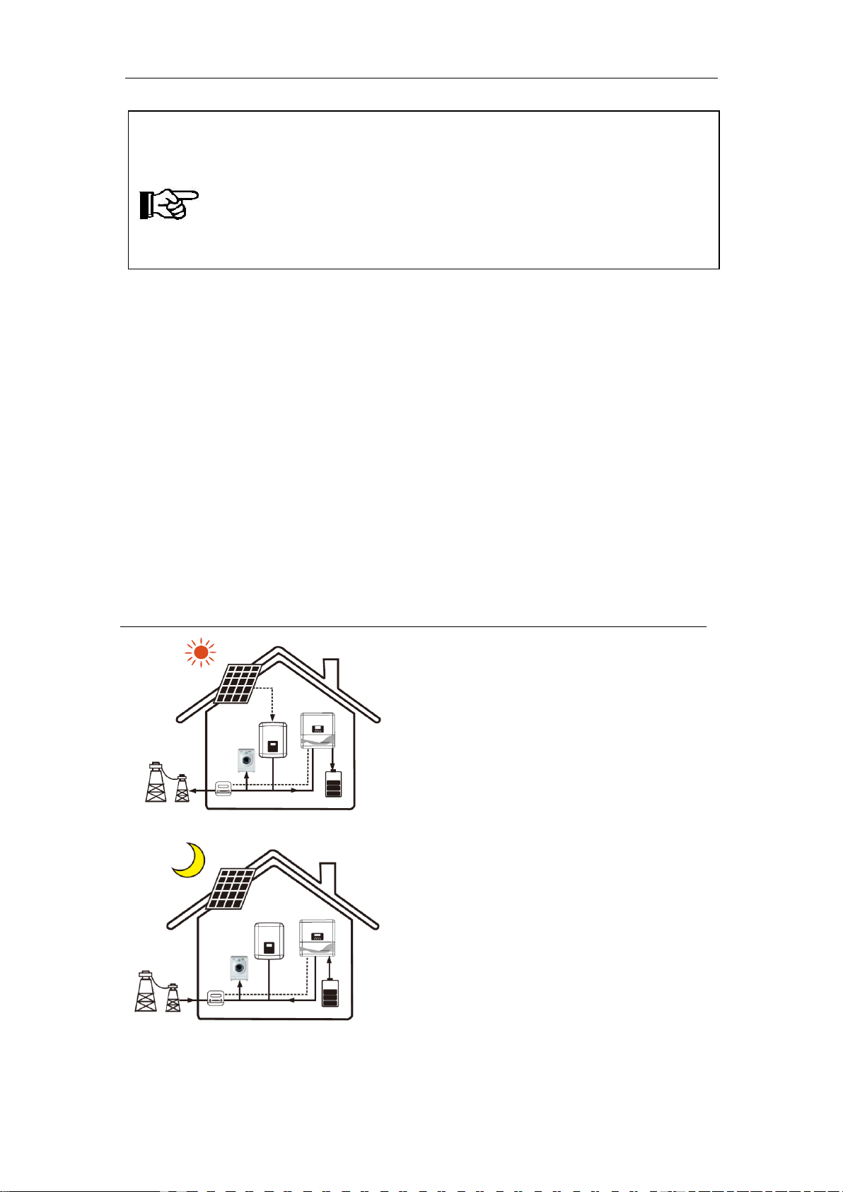
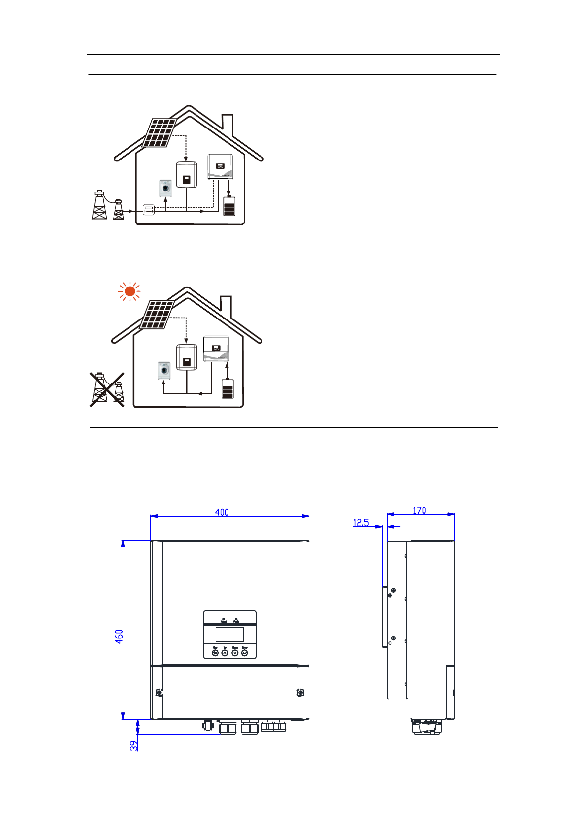
3.2 Work Modes............................................................................................................................................ 11
3.3 Dimension................................................................................................................................................ 13
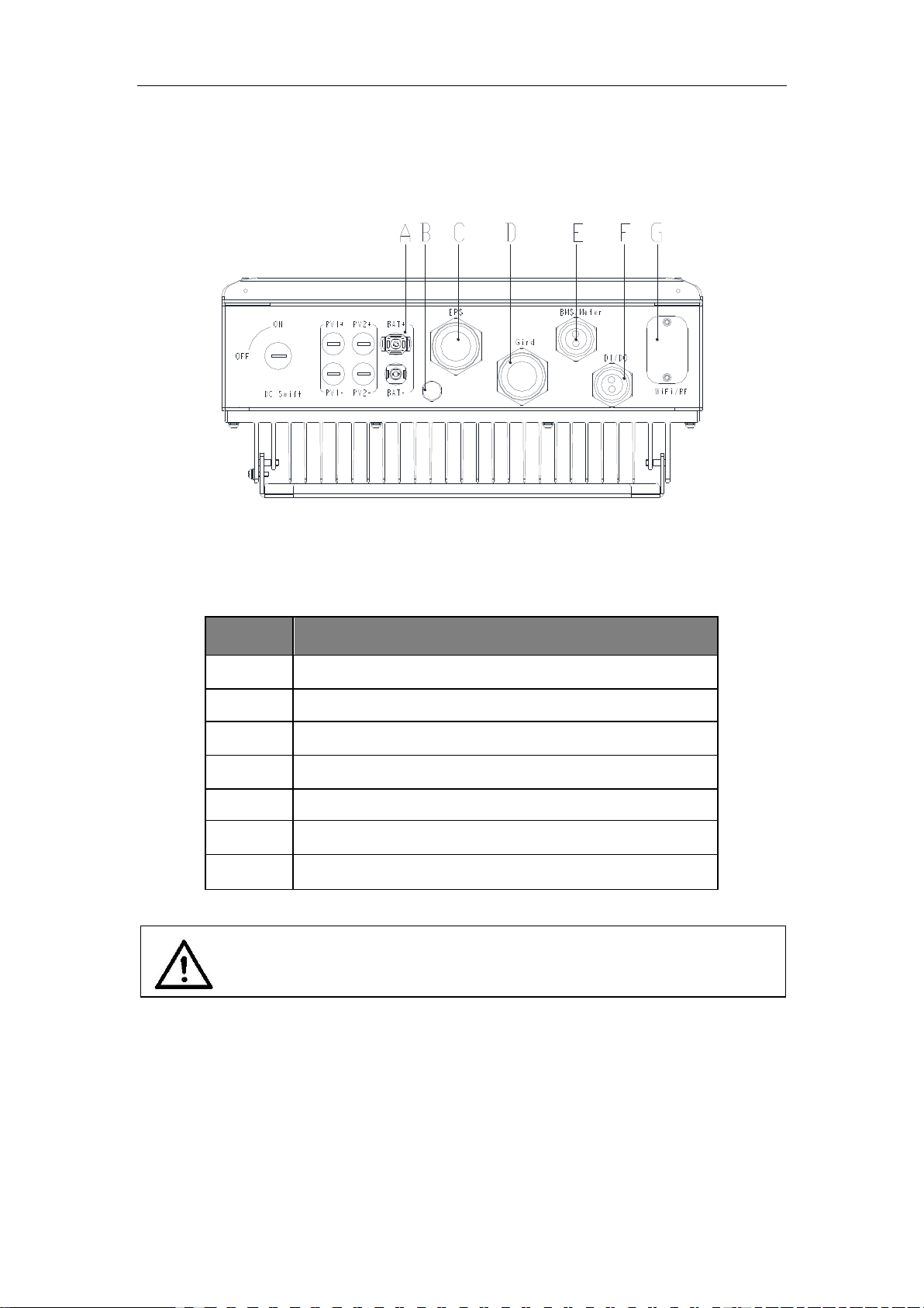
3.4 Terminals of inverter ............................................................................................................................. 14
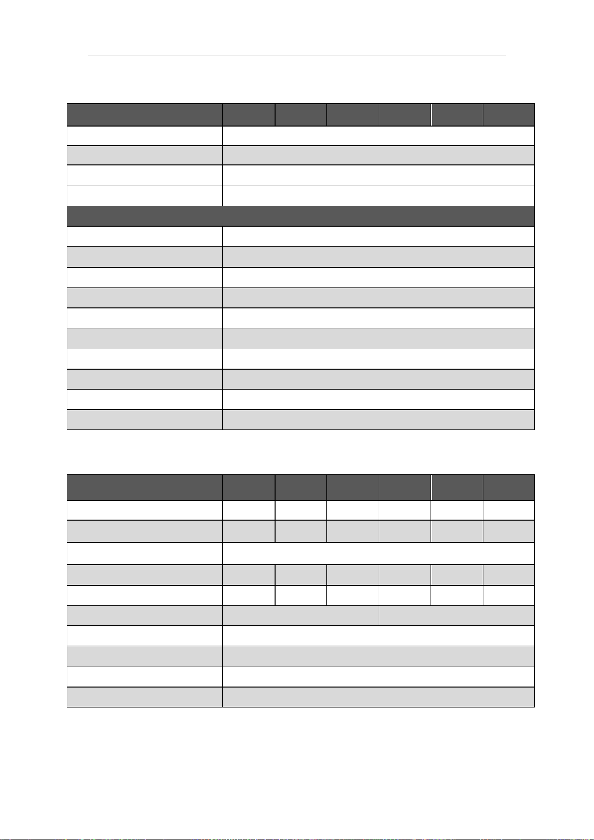
4 Technical Data..................................................................................................................................................... 15
4.1 AC output / input.................................................................................................................................... 15
4.2 Internal Charger...................................................................................................................................... 15
4.3 Efficiency, Safety and Protection......................................................................................................... 16
4.4 EPS output (apply to version O, I) ....................................................................................................... 16
4.5 General Data ........................................................................................................................................... 17
5 Installation ........................................................................................................................................................... 18
5.1 Check for Physical Damage................................................................................................................... 18
5.2 Packing..................................................................................................................................................... 18
5.3 Installati on Precaution .......................................................................................................................... 19
5.4 Space Requirement................................................................................................................................ 20
5.5 Installation steps .................................................................................................................................... 20
6 Electrical Connection ......................................................................................................................................... 22
6.1 Grid Connection...................................................................................................................................... 22
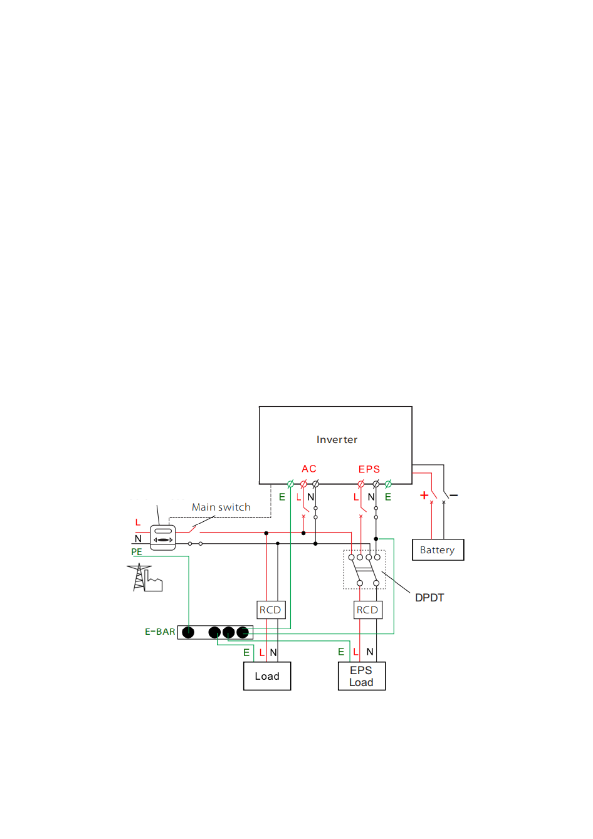
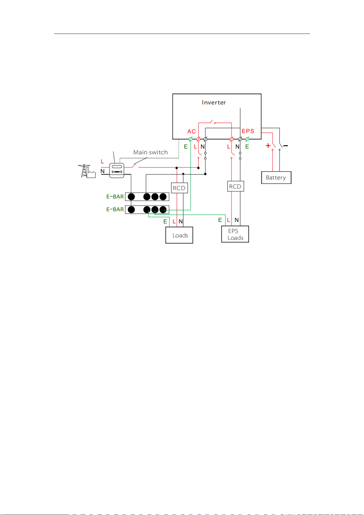
6.2 EPS Connection (apply to O Version and I Version only) ................................................................ 23
6.3 Battery Conn ecti on ................................................................................................................................ 28
6.4 Meter Conn ection .................................................................................................................................. 31
6.5 DRM Connection .................................................................................................................................... 32
6.6 Terminal Block Connection................................................................................................................... 33
6.7 WiFi Connection ..................................................................................................................................... 33
6.8 RF Connection (optional) ...................................................................................................................... 34
6.9 Inverter Manipulation ........................................................................................................................... 34
7 Setting................................................................................................................................................................... 37
7.1 Control Panel........................................................................................................................................... 37
7.2 Menu Structure ...................................................................................................................................... 38
7.3 LCD Operation......................................................................................................................................... 38
7.4 Quick Start Settings............................................................................................................................... 40
8 Troubleshooting.................................................................................................................................................. 42
8.1 Trouble shooting.................................................................................................................................... 42

8.2 Routine maintenance ............................................................................................................................ 45
9 Decommissioning ............................................................................................................................................... 46
9.1 Remove the Inverter .............................................................................................................................. 46
9.2 Packaging................................................................................................................................................. 46
9.3 Storage and Transportation ................................................................................................................. 46
10 Warranty Card................................................................................................................................................... 47

1
1 Notes on this Manual
1.1 Scope of Validity
This manual is an integral part of TSOL Inverter, it describes the assembly, installation,
commissioning, maintenance and failure of the product. Please read it carefully before
operating.
TSOL-A3.0K-H
TSOL-A3.6K-H
TSOL-A4.0K-H
TSOL-A4.6K-H
TSOL-A5.0K-H
TSOL-A6.0K-H
Note: “3.0K” means 3kW.
Oversion: “EPS function” will be available with an outer changeover device installed.
Iversion: “EPS function” available as unit already content an inner changeover device.
Uversion: without “EPS function”.
1.2 Target Group
This manual is for qualified electricians. The tasks described in this manual only can be
performed by qualified personnel.
1.3 Symbols Used
The following types of safety instructionsand general information appear in this document
as described below:
Note!
“Note” provides tips that are valuable for the optimal operation of our
product.
Caution!
“Caution” indicates a hazardous situation which, if not avoided, could result in
minor or moderate injury.
Warning!
“Warning” indicates a hazardous situation which, if not avoided, could result in
death or serious injury.
Danger!
“Danger” indicates a hazardous situation which, if not avoided, will result in
death or serious injury.

2
2 Safety
2.1 Important Safety Instructions
Prior to the application, please read this section carefully to ensure correct and safe
application. Please keep the user manual properly.
Accessories only together with the inverter shipment are recommended here.
Otherwise may result in a risk of fire, electric shock, or injury to person.
Make sure that existing wiring is in good condition and that wire is not undersized.
Warning!
Risk of electric shock!
Warning!
Do not operate the inverter when the device is running.
Warning!
Authorized service personnel must disconnect both AC and Battery power
from inverter before attempting any maintenance or cleaning or working on
any circuits connected to inverter.
Caution!
Possible damage to health as a result of the effects of radiation!
Do not stay closer than 20 cm to inverter for any length of time.
Caution!
Danger of burninjuries due to hot enclosure parts!
During operation, the upper lid of the enclosure and the enclosure body
may become hot.
Only touch the lower enclosure lid during operation.
Danger!
Danger to life due to high voltages in the inverter!
All work must be carried out by qualified electrician.
The appliance is not to be used by children or persons with reduced
physical sensory or mental capabilities, or lack of experience and
knowledge, unless they have been given supervision or instruction.
Children should be supervised to ensure that they do not play with the
appliance.

3
Do not disassemble any parts of inverter which are not mentioned in installation guide.
It contains no user-serviceable parts. See Warranty for instructions on obtaining service.
Attempting to service the inverter yourself may result in a risk of electricshock or fire
and will void your warranty.
Keep away from flammable, explosive materialsto avoid fire disaster.
The installation place should be away from humid or corrosive substance.
Authorized service personnel must use insulated tools when installing or working with
this equipment.
The unit contains capacitors that remain charged to a potentially lethal voltage after the
MAINS and battery has been disconnected.
Hazardous voltage will present for up to 5 minutes after disconnection from power
supply.
CAUTION-RISK of electric shock fromenergy stored in capacitor, never operate on the
inverter couplers, the MAINS cables and Battery cables when power is applied. After
switching off the battery and Mains, always wait for 5minutes to let the intermediate
circuit capacitors discharge before unplugging battery plugin and MAINS couplers.
When accessing the internal circuit of inverter, it is very important to wait 5 minutes
before operating the power circuit or demounting the electrolyte capacitors inside the
device. Do not open the device in advance since the capacitors require time to
sufficiently discharge!
Measure the voltage between terminals UDC+ and UDC- with a multi-meter
(impedance at least 1Mohm) to ensure that the device is discharged before beginning
work (35VDC) inside the device.
Lightning will cause damage either from a direct strike or from surges due to a nearby
strike.
Induced surges are the most likely cause of lightning damage in majority or installations,
especially in rural areas where electricity is usually provided by long overhead lines.
Specialists in lightning protection should be consulted during the end use application.
Using appropriate externallightning protection, the effect of a direct lightning strike into
a building can be mitigated in a controlled way, and the lightning current can be
discharged into the ground.
Installation of SPDs to protect the inverter against mechanical damage and excessive
stress include a surge arrester in case of a building with external lightning protection
system (LPS) when separation distance is kept.
To protect the AC system, surge suppression devices (SPD type2) should be fitted at
the main incoming point of AC supply (at the consumer‟s cutout), located between the
inverter and the meter/distribution system; SPD (test impulse D1) for signal line
according to EN 61632-1.
Anti-Islanding Effect
Islanding effect is a special phenomenon that grid-connected systemstill supplies
power to the nearby grid when the voltage loss is happened in the power system. It is
dangerous for maintenance personnel and the public.
TSOL series inverter provides Active Frequency Drift (AFD) to prevent islanding effect.

4
PE Connection andLeakage Current
The end-use application shall monitor the protective conductor by residual current
operated protective device (RCD) with rated fault current Ifn≤240mA which
automatically disconnects the device in case of a fault.
Incorrect grounding can cause physical injury, death or equipment malfunction and
increase electromagnetic.
Make sure that grounding conductor is adequately sized as required by safety
regulations.
Do not connect the ground terminals of the unit in series in case of a multiple installation.
This product can cause current with a d.c component, Where a residualcurrent
operated protective (RCD) or monitoring (RCM) device is used for protection in case of
direct or indirect contact, only an RCD or RCM of type B isallowed on the supply side of
this product.
For United Kingdom
The installation that connects the equipment to the supply terminals shall comply with
the requirements of BS 7671.
No protection settings can be altered.
User shall ensure that equipment is so installed, designed and operated to maintain at
all times compliance with the requirements of ESQCR22(1)(a).
For Australia and New Zealand
Electrical installation and maintenance shall be conducted by licensed electrician and
shall comply with Australia National Wiring Rules.
BatterySafety Instructions
TSOL Series inverter should be worked with high voltage battery, for the specific
parameters such as battery type, nominal voltage and nominal capacity etc., please refer
to section 4.3.
As accumulator batteries may contain potential electric shockand short-circuit current
danger, to avoid accidents that might be thus resulted, the following warnings should be
observed during battery replacement:
1: Do not wear watches, rings or similar metallic items.
2: Use insulated tools.
3: Put on rubber shoes and gloves.
4: Do not place metallic tools and similar metallic parts on the batteries.
5: Switch off load connected to the batteries before dismantling battery connection
terminals.
Warning!
High leakage current!
Earth connection is essential before connecting supply.

5
6: Only personal with proper expertise can carry out the maintenance of accumulator
batteries.
2.2 Explanation of Symbols
This section gives an explanation of allthe symbols shown on the inverter and on the type
label.
CE mark.
The inverter complies with the requirements of the applicable CE guild
lines.
TUV certified.
RCM remark.
SAA certification.
Beware of hot surface.
The inverter can become hot during operation. Avoid contact during
operation.
Danger of high voltages.
Danger to life due to high voltagesin the inverter!
Danger.
Risk of electric shock!
Observe enclosed documentation.
The inverter can not be disposed together with the household waste.
Disposal information can be found in the enclosed documentation.
Do not operate this inverter untilit is isolated frombattery and mains
Danger to life due to high voltage.
There is residual voltage existing in the inverter after powering off, which
needs 5 min to discharge.
• Wait 5 min before you open the upper lid or the DC lid.

6
2.3 CE Directives
This chapter follows the requirements of the European low voltage directives, which
contains the safety instructions and conditions of acceptability for the end use system,
which you must followwhen installing, operating and servicing the unit. If ignored, physical
injury or death may follow, or damage may occur to the unit. Read this instructions before
you work on the unit. If you are unable to understand the dangers, warnings, cautions or
instructions, please contact an authorized service dealer before installing. Operating and
servicing the unit.
The Grid connected inverter meets the requirement stipulated in Low Voltage Directive
(LVD) 2014/35/EU and Electromagnetic Compatibility (EMC) Directive 2014/30/EU. The
unit is based on:
EN 62109-1: 2010; EN 62109-2:2011; IEC 62109-1(ed.1) ; IEC62109-2(ed.1)
EN 61000-6-3:2007+A: 2011; EN61000-6-1:2007; EN61000-6-2:2005
The grid connected inverter leave the factory completely connecting device and ready for
connection to the mains, the unit shall be installed in accordance with national wiring
regulations. Compliance with safety regulations depends upon installing and configuring
system correctly, including using the specified wires. The system must be installed only by
professional assemblers who are familiar with requirements for safety and EMC. The
assembler is responsible for ensuring that the end system complies with all the relevant
laws in the country where it is to be used.
The individualsubassembly of the system shall be interconnected by means of the wiring
methods outlined in national/internationalsuch as the national electric code (NFPA) No.70
or VDE regulation 0107.

7
3 Introduction
3.1 Basic features
TSOL Series is a high-quality inverter which can store energy into battery.
The inverter can be used to optimize self-consumption, store in the battery for future use
or feed-in to public grid. Work mode depends on the battery and user‟s preference. It can
provide power for emergency use during the grid lost by using the energy from battery.
System Diagram
TSOL Series is designed with two EPS versions for customer to choose based on the
local rules.
O Version applies to the wiring rules that require the Live line and Neutral line of EPS
must be disconnected with the Live line and Neutral line of grid (applies to most
countries).
Meter

8
·
WIRING SYSTEM FOR O Version
L
N
PE
Battery Backup Load On Grid Load
Grid
DC Breaker Changeover
Device
(DPDT)
AC Breaker
PE-Bar
AC Breaker
Fuse
Fuse
AC Breaker
Fuse
To Meter
To Battery
Home Electric
Meter
Single Phase
Meter

9
I Version applies to the wiring rules that require Neutral line of alternative supply
must NOT be isolated or switched (applies to wiring rules AS/NZS_3000:2012 for
Australia and New Zealand).
Meter

10
·
WIRING SYSTEM FOR I Version
L
N
PE
Battery Backup Load On Grid Load
Single Phase
Meter
Grid
DC Breaker AC Breaker AC Breaker
PE-Bar
N-Bar
AC Breaker
To Meter
To Battery
Home Electric
Meter

11
3.2 Work Modes
TSOL Series inverter provides multiple work modes based on different requirements.
Work mode: Self-use
Priority: load>battery>grid
This mode applies the area that has lowfeed-in
tariff and high energy price.
In the case of the external generator, the power
generated will be used to supply the local loads
firstly, then to charge the battery. The
redundant power will export to the public grid.
In the absence of the external generator, or
the power is not enough, batterywill discharge
for local loads firstly, and grid will supply power
when the battery capacity is not enough.
Note!
Please control the home loads, and make sure it‟s within the “EPS output
rating” under EPS mode, otherwise the inverter will shut down with an
“overload fault” warning.
Please confirm with the mains grid operator whether there are any special
regulations for grid connection.

12
Work mode: Force time use
Priority: battery>load>grid (when charging)
Priority: load>battery>grid (when
discharging)
This mode applies the area that has electricity
price between peak and valley. User can use
off-peak electricity to charge the battery.
The charging and discharging time can be set
flexibly.
Work mode: Feed in Priority
Priority: load>grid>battery
This mode applies the area that has high
feed-in tariff and export control.
In the case of the external generator, the power
generated will be used to supplythe local loads
firstly, then export to the public grid. The
redundant power will charge the battery.
In the absence of the external generator, or the
power is not enough, battery will discharge for
local loads firstly, and grid will supply power
when the battery capacity and power
generation isnot enough.
Work mode: Back up mode
Priority: battery>load>grid
This mode applies the area that has frequent
power outages. And this mode ensures the
battery will has enough energy to supply when
the grid is off.
In the case of external power generation
equipment, the power generated will be used to
charge the battery fully firstly, then supply the
local loads. The redundant power will export to
the public grid.
In the absence of an external power generation
device, charge the battery with the public grid.
The inverter will switch to EPS mode only when
the grid is abnormal.

13
Work mode: Peak and valleymode
Priority: battery>load>grid (whencharging)
Priority: load>grid (whendischarging)
Charge the battery according to the set power
within the set charging time; During the set
discharge time, the battery is discharged
according tothe set power. Other time according
to Self Use mode.
*EPS Status
When the grid is off, system will supply
emergency power from battery to supply
the home loads. (Battery is necessary in
EPS mode.)
3.3 Dimension

14
3.4 Terminals of inverter
Object
Description
A
Battery connection area
B
Waterproof valve
C
EPS output
D
GRID output
E
BMS/Meter
F
DI/DO
G
WiFi/RF port for external Pocket WiFi/RF
Warning!
Qualified electrician will be required for the installation.

15
4 Technical Data
4.1 AC output / input
Model
TSOL-A3.
0K-H
TSOL-A3.
6K-H
TSOL-A4.
0K-H
TSOL-A4.
6K-H
TSOL-A5.
0K-H
TSOL-A6.
0K-H
AC output
Nominal AC power[W]
3000
3680
4000
4600
5000
6000
Max. apparentAC power[VA]
3000
3680
4000
4600
5000
6000
Ratedgrid voltage(range)[V]
220/230/240 (180 to 270)
Ratedgrid frequency[Hz]
50/60
Nominal AC current [A]
13
16
17.3
20
21.7
26.1
Max.AC current [A]
14
16
18.6
21.4
23.2
27.9
Displacementpowerfactor
0.8 leading...0.8 lagging
Total harmonicdistortion (THDI)
< 3%
Loadcontrol
optional
AC input
Max. apparentAC power[VA] (O&U
Version)
3000
3680
4000
4600
5000
6000
Max. apparentAC power[VA] (I
Version)
3000+3000
(bypass)
3680+3680
(bypass)
4000+4000
(bypass)
4600+4600
(bypass)
5000+5000
(bypass)
6000+6000
(bypass)
Ratedgrid voltage (range)[V]
220/230/240 (180 to 270)
Ratedgrid frequency[Hz]
50/60
Nominal ACcurrent [A] (O&U
Version)
13
16
17.3
20
21.7
26.1
Max.AC current [A] (O&U Version)
14
16
18.6
21.4
23.2
27.9
Nominal ACcurrent [A] (I Version)
13+13
(bypass)
16+16
(bypass)
17.3+17.3
(bypass)
20+20
(bypass)
21.7+21.7
(bypass)
26.1+26.1
(bypass)
Max. AC current [A] (I Version)
14+14
(bypass)
16+16
(bypass)
18.6+18.6
(bypass)
21.4+21.4
(bypass)
23.2+23.2
(bypass)
27.9+27.9
(bypass)
Displacementpowerfactor
0.8 leading...0.8 lagging
AC inrushcurrent[A]
35
AC maximum outputfaultcurrent [A]
80
4.2 Internal Charger
Model
TSOL-A3.
0K-H
TSOL-A3.
6K-H
TSOL-A4.
0K-H
TSOL-A4.
6K-H
TSOL-A5.
0K-H
TSOL-A6.
0K-H
Battery type
Lithium battery
Battery voltage range [V]
90-400
Recommended batteryvoltage [V]
300
Recommended batterycapacity
[KWh]
4.8-16.8
Max. charge/discharge current [A]
20A (adjustable)
Peak charge/discharge current [A]
30A, 30s
Communication interfaces
CAN
Reverse connect protection
Yes

16
4.3 Efficiency, Safety and Protection
Model
TSOL-A3.
0K-H
TSOL-A3.
6K-H
TSOL-A4.
0K-H
TSOL-A4.
6K-H
TSOL-A5.
0K-H
TSOL-A6.
0K-H
MPPT efficiency
99.90%
Euro efficiency
97.00%
Max. efficiency
97.80%
Max. Battery discharge efficiency
(BAT to AC) (@full load)
97.00%
Safety & Protection
Over/under voltage protection
YES
DC isolation protection
YES
Monitoring ground fault protection
YES
Grid protection
YES
DC injection monitoring
YES
Back feed current monitoring
YES
Residual current detection
YES
Anti-islanding protection
YES
Over load protection
YES
Over heat protection
YES
4.4 EPS output (apply to version O, I)
Model
TSOL-A3.
0K-H
TSOL-A3.
6K-H
TSOL-A4.
0K-H
TSOL-A4.
6K-H
TSOL-A5.
0K-H
TSOL-A6.
0K-H
EPS rated power[VA]
3000
3680
4000
4600
5000
6000
Max. EPS power[VA]
3000
3680
4000
4600
5000
6000
EPS rated voltage [Vac],
Frequency[Hz]
230,50/60
EPS rated current[A]
13
16
17.3
20
21.7
26.1
Max. EPS current[A]
14
16
18.6
21.4
23.2
27.9
EPS peak power[W]
5500,30s
8000,30s
Switch time[s]
<0.5
Total harmonicdistortion (THDV)
<3%
Parallel operation
Yes
Compatiblewiththegenerator
Yes(signal provided only)
This manual suits for next models
5
Table of contents
Other TSUNESS Inverter manuals
Popular Inverter manuals by other brands

Sofar
Sofar HYD3000-ES user manual

Siemens
Siemens PM250 Hardware installation manual

Bolanmu Energy
Bolanmu Energy xtm 1500-12 quick guide

Leeson
Leeson 174603 Installation and operation manual

Advanced Energy
Advanced Energy AE 75TX Installation and operation

EasyDrive Electric
EasyDrive Electric GT200-4T0007G user manual

Defort
Defort DCI-305 user manual

Link electronics
Link electronics IEC-833 Specification sheet

Jntech
Jntech JNP550L-V5 Quick installation

Maxeon
Maxeon SPR-P6-555-UPP installation instructions

LiteGear
LiteGear Inverter Power System Installation instructions and user manual

Sofar
Sofar ME 5KTL-3PH user manual