TSUNESS TSOL-H3.0K-H User manual
TSOL-H3.0K-H
TSOL-H3.6K-H
TSOL-H4.0K-H
TSOL-H4.6K-H
TSOL-H5.0K-H
TSOL-H6.0K-H


Content
1 Notes on this Manual............................................................................................................................................1
1.1 Scope of Validity........................................................................................................................................1
1.2 Target Group ..............................................................................................................................................1
1.3 Symbols Used.............................................................................................................................................1
2 Safety .......................................................................................................................................................................2
2.1 Important Safety Instructions.................................................................................................................2
2.2 Explanation of Symbols............................................................................................................................6
2.3 CE Directives...............................................................................................................................................7
3 Introduction............................................................................................................................................................8
3.1 Basic features.............................................................................................................................................8
3.2 Work Modes............................................................................................................................................ 12
3.3 Dimension................................................................................................................................................ 14
3.4 Terminals of PV inverter ....................................................................................................................... 15
4 Technical Data..................................................................................................................................................... 16
4.1 DC input ................................................................................................................................................... 16
4.2 AC output / input.................................................................................................................................... 16
4.3 Internal Charger...................................................................................................................................... 17
4.4 Efficiency, Safety and Protection......................................................................................................... 17
4.5 EPS output (apply to version O, I) ....................................................................................................... 18
4.6 General Data ........................................................................................................................................... 18
5 Installation ........................................................................................................................................................... 19
5.1 Check for Physical Damage................................................................................................................... 19
5.2 Packing..................................................................................................................................................... 19
5.3 Installati on Precaution .......................................................................................................................... 20
5.4 Space Requirement................................................................................................................................ 21
5.5 Installation steps .................................................................................................................................... 21
6 Electrical Connection ......................................................................................................................................... 23
6.1 PV connection ......................................................................................................................................... 23
6.2 Grid Connection...................................................................................................................................... 25
6.3 EPS Connection (apply to O Version and I Version only) ................................................................ 27
6.4 Battery Conn ecti on ................................................................................................................................ 31
6.5 Meter Conn ection .................................................................................................................................. 34
6.6 DRM Connection .................................................................................................................................... 36
6.7 Terminal Block Connection................................................................................................................... 36
6.8 WiFi Connection ..................................................................................................................................... 37
6.9 RF Connection (optional)...................................................................................................................... 37
6.10 Inverter Manipulation......................................................................................................................... 38
7 Setting................................................................................................................................................................... 40
7.1 Control Panel........................................................................................................................................... 40
7.2 Menu Structure ...................................................................................................................................... 41
7.3 LCD Operation......................................................................................................................................... 42
7.4 Quick Start Settings............................................................................................................................... 44

8 Troubleshooting.................................................................................................................................................. 46
8.1 Trouble shooting.................................................................................................................................... 46
8.2 Routine maintenance ............................................................................................................................ 49
9 Decommissioning ............................................................................................................................................... 50
9.1 Remove the Inverter .............................................................................................................................. 50
9.2 Packaging................................................................................................................................................. 50
9.3 Storage and Transportation................................................................................................................. 50
10 Warranty Card................................................................................................................................................... 51

1
1 Notes on this Manual
1.1 Scope of Validity
This manual is an integral part of TSOL Inverter, it describes the assembly, installation,
commissioning, maintenance and failure of the product. Please read it carefullybefore
operating.
TSOL-H3.0K-H
TSOL-H3.6K-H
TSOL-H4.0K-H
TSOL-H4.6K-H
TSOL-H5.0K-H
TSOL-H6.0K-H
Note: “3.0K” means 3kW.
Oversion: “EPS function” will be available with an outer changeover device installed.
Iversion: “EPS function” available as unit already content an inner changeover device.
Uversion: without “EPS function”.
1.2 Target Group
This manual is for qualified electricians. The tasks described in this manual only can be
performed by qualified personnel.
1.3 Symbols Used
The following types of safety instructionsand general information appear in this document
as described below:
Note!
“Note” provides tips that are valuable for the optimal operation of our
product.
Caution!
“Caution” indicates a hazardous situation which, if not avoided, could result in
minor or moderate injury.
Warning!
“Warning” indicates a hazardous situation which, if not avoided, could result in
death or serious injury.
Danger!
“Danger” indicates a hazardous situation which, if not avoided, will result in
death or serious injury.
2
2 Safety
2.1 Important Safety Instructions
Warning!
Ensure input DC voltage ≤Max. DC voltage .Over voltage may cause
permanent damage to inverter or other losses, which will not be included in
warranty!
Note!
Grounding the PVgenerator.
Comply with the local requirements for grounding the PV modules and the
PV generator. It is recommends connecting the generator frame and other
electrically conductive surfaces in a manner which ensures continuous
conduction and ground these in order to have optimal protection of system
and persons.
Caution!
Possible damage to health as a result of the effects of radiation!
Do not stay closer than 20 cm to inverter for any length of time.
Caution!
Danger of burninjuries due to hot enclosure parts!
During operation, the upper lid of the enclosure and the enclosure body
may become hot.
Only touch the lower enclosure lid during operation.
Danger!
Danger to life due to high voltages in the inverter!
All work must be carried out by qualified electrician.
The appliance is not to be used by children or persons with reduced
physical sensory or mental capabilities, or lack of experience and
knowledge, unless they have been given supervision or instruction.
Children should be supervised to ensure that they do not play with the
appliance.

3
Prior to the application, please read this section carefully to ensure correct and safe
application. Please keep the user manual properly.
Accessories only together with the inverter shipment are recommended here.
Otherwise may result in a risk of fire, electric shock, or injury to person.
Make sure that existing wiring is in good condition and that wire is not undersized.
Do not disassemble any parts of inverter which are not mentioned in installation guide.
It contains no user-serviceable parts. See Warranty for instructions on obtaining service.
Attempting to service the inverter yourself may result in a risk of electricshock or fire
and will void your warranty.
Keep away from flammable, explosive materials to avoid fire disaster.
The installation place should be away from humid or corrosive substance.
Authorized service personnel must use insulated tools when installing or working with
this equipment.
PV modules shall have an IEC 61730 class A rating.
Never touch either the positive or negative pole of PV connecting device. Strictly
prohibit touching both of them at the same time.
The unit contains capacitors that remain charged to a potentiallylethal voltage after the
MAINS, battery and PV supply has been disconnected.
Hazardous voltage will present for up to 5 minutes after disconnection from power
supply.
CAUTION-RISK of electric shock fromenergy stored in capacitor, never operate on the
inverter couplers, the MAINS cables, Battery cables, PV cables or the PV generator
when power is applied. After switching off the PV, battery and Mains, always wait for
5minutes to let the intermediate circuit capacitors discharge before unplugging DC,
battery plugin and MAINS couplers.
When accessing the internal circuit of inverter, it is very important to wait 5 minutes
before operating the power circuit or demounting the electrolyte capacitors inside the
device. Do not open the device in advance since the capacitors require time to
sufficiently discharge!
Measure the voltage between terminals UDC+ and UDC- with a multi-meter
(impedance at least 1Mohm) to ensure that the device is discharged before beginning
work (35VDC) inside the device.
Warning!
Risk of electric shock!
Warning!
Do not operate the inverter when the device is running.
Warning!
Authorized service personnel must disconnect both AC and DC power from
inverter before attempting any maintenance or cleaning or working on any
circuits connected to inverter.

4
Surge protection devices (SPDs) for PV installation
Lightning will cause damage either from a direct strike or from surges due to a nearby
strike.
Induced surges are the most likely cause of lightning damage in majority or installations,
especially in rural areas where electricity is usually provided by long overhead lines.
Surge may be included on both the PV array conduction and the AC cables leading to
the building.
Specialists in lightning protection should be consulted during the end use application.
Using appropriate externallightning protection, the effect of a direct lightning strike into
a building can be mitigated in a controlled way, and the lightning current can be
discharged into the ground.
Installation of SPDs to protect the inverter against mechanical damage and excessive
stress include a surge arrester in case of a building with external lightning protection
system (LPS) when separation distance is kept.
To protect the DC system, surge suppression device (SPD type2) should be fitted at the
inverter end of the DC cabling and at the array located between the inverter and the PV
generator, if the voltage protection level (VP) of the surge arresters isgreater than
1100V, an additionalSPD type 3 required for surge protection for electrical devices.
To protect the AC system, surge suppression devices (SPD type2) should be fitted at
the main incoming point of AC supply (at the consumer‟s cutout), located between the
inverter and the meter/distribution system; SPD (test impulse D1) for signal line
according to EN 61632-1.
All DC cables should be installed to provide asshort a run as possible, and positive and
negative cables of the string or main DC supplyshould be bundled together. Avoiding
the creation of loops in the system. This requirement for short runs and bundling
includes any associated earth bundling conductors.
Spark gap devices are not suitable to be used in DC circuits once conducting, they
won‟t stop conducting until the voltage across their terminals is typically more than 30
volts.
Anti-Islanding Effect
Islanding effect is a special phenomenon that grid-connected PVsystem still supplies
power to the nearby grid when the voltage loss is happened in the power system. It is
dangerous for maintenance personnel and the public.
TSOL series inverter provides Active Frequency Drift (AFD) to prevent islanding effect.
WARNING!
Over-voltage protection with surge arresters should be provided when the
PV power system is installed.
The grid connected inverter is not fitted with SPDs in both PV input side and
MAINS side.

5
PE Connection andLeakage Current
The end-use application shall monitor the protective conductor by residual current
operated protective device (RCD) with rated fault current Ifn≤240mA which
automatically disconnects the device in case of a fault.
The device is intended to connect to a PV generator with a capacitance limit of about
700nf.
Incorrect grounding can cause physical injury, death or equipment malfunction and
increase electromagnetic.
Make sure that grounding conductor is adequately sized as required by safety
regulations.
Do not connect the ground terminals of the unit in series in case of a multiple installation.
This product can cause current with a d.c component, Where a residualcurrent
operated protective (RCD) or monitoring (RCM) device is used for protection in case of
direct or indirect contact, only an RCD or RCM of type B isallowed on the supply side of
this product.
For United Kingdom
The installation that connects the equipment to the supply terminals shall comply with
the requirements of BS 7671.
Electrical installation of PV system shall comply with requirements of BS 7671 and IEC
60364-7-712.
No protection settings can be altered.
User shall ensure that equipment is so installed, designed and operated to maintain at
all times compliance with the requirements of ESQCR22(1)(a).
For Australia and New Zealand
Electrical installation and maintenance shall be conducted by licensed electrician and
shall comply with Australia National Wiring Rules.
BatterySafety Instructions
TSOL Series inverter should be worked with high voltage battery, for the specific
parameters such as battery type, nominal voltage and nominal capacity etc., please refer
to section 4.3.
As accumulator batteries may contain potential electric shockand short-circuit current
danger, to avoid accidents that might be thus resulted, the following warnings should be
observed during battery replacement:
1: Do not wear watches, rings or similar metallic items.
2: Use insulated tools.
Warning!
High leakage current!
Earth connection is essential before connecting supply.
6
3: Put on rubber shoes and gloves.
4: Do not place metallic tools and similar metallic parts on the batteries.
5: Switch off load connected to the batteries before dismantling battery connection
terminals.
6: Only personal with proper expertise can carry out the maintenance of accumulator
batteries.
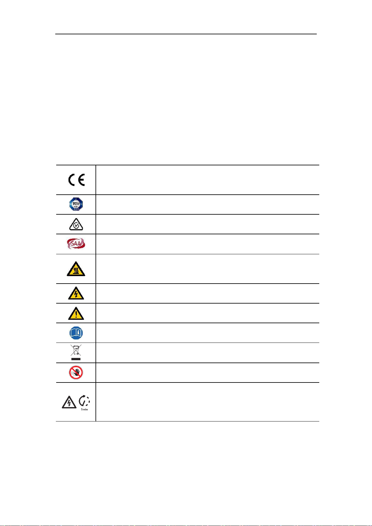
2.2 Explanation of Symbols
This section gives an explanation of allthe symbols shown on the inverter and on the type
label.
CE mark.
The inverter complies with the requirements of the applicable CE guild
lines.
TUV certified.
RCM remark.
SAA certification.
Beware of hot surface.
The inverter can become hot during operation. Avoid contact during
operation.
Danger of high voltages.
Danger to life due to high voltagesin the inverter!
Danger.
Risk of electric shock!
Observe enclosed documentation.
The inverter can not be disposed together with the household waste.
Disposal information can be found in the enclosed documentation.
Do not operate thisinverter until it is isolated frombattery, mains and
on-site PV generation suppliers.
Danger to life due to high voltage.
There is residual voltage existing in the inverter after powering off, which
needs 5 min to discharge.
• Wait 5 min before you open the upper lid or the DC lid.

7
2.3 CE Directives
This chapter follows the requirements of the European low voltage directives, which
contains the safety instructions and conditions of acceptability for the end use system,
which you must followwhen installing, operating and servicing the unit. If ignored, physical
injury or death may follow, or damage may occur to the unit. Read this instructions before
you work on the unit. If you are unable to understand the dangers, warnings, cautions or
instructions, please contact an authorized service dealer before installing. Operating and
servicing the unit.
The Grid connected inverter meets the requirement stipulated in Low Voltage Directive
(LVD) 2014/35/EU and Electromagnetic Compatibility (EMC) Directive 2014/30/EU. The
unit is based on:
EN 62109-1: 2010; EN 62109-2:2011; IEC62109-1(ed.1) ; IEC62109-2(ed.1)
EN 61000-6-3:2007+A: 2011; EN61000-6-1:2007; EN61000-6-2:2005
In case of installation in PV system, startup of the unit (i.e. start of designated operation) is
prohibited until it is determined that the full system meets the requirements stipulated in
EC Directive (2014/35/EU, 2014/30/EU, etc.)
The grid connected inverter leave the factory completely connecting device and ready for
connection to the mains and PV supply ,the unit shall be installed in accordance with
nationalwiring regulations. Compliance with safety regulations depends upon installing
and configuring system correctly, including using the specified wires. The system must be
installed only by professional assemblers who are familiar with requirements for safety
and EMC. The assembler isresponsible for ensuring that the end system complies with all
the relevant laws in the country where it is to be used.
The individualsubassembly of the system shall be interconnected by means of the wiring
methods outlined in national/international such as the national electric code (NFPA) No.70
or VDE regulation 0107.

8
3 Introduction
3.1 Basic features
TSOL Series is a high-quality inverter which can convert solar energy to AC energy and
store energy into battery.
The inverter can be used to optimize self-consumption, store in the battery for future use
or feed-in to public grid. Work mode depends on PV energy and user‟s preference. It can
provide power for emergency use during the grid lost by using the energy from battery and
inverter (generated fromPV).
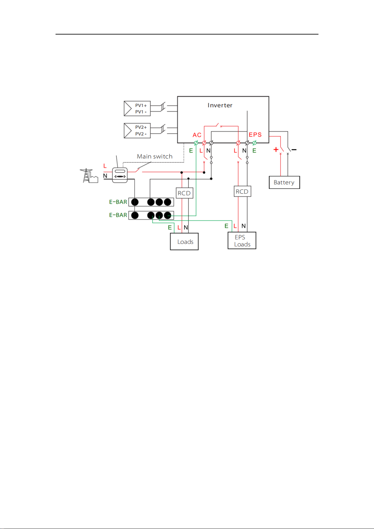
System Diagram
TSOL Series is designed with two EPS versions for customer to choose based on the
local rules.
O Version applies to the wiring rules that require the Live line and Neutral line of EPS
must be disconnected with the Live line and Neutral line of grid (appliesto most
countries).
Meter

9
·
WIRING SYSTEM FOR O Version
L
N
PE
Battery Backup Load On Grid Load
Grid
DC Breaker Changeover
Device
(DPDT)
AC Breaker
PE-Bar
PV2
PV1
AC Breaker
Fuse
Fuse
AC Breaker
Fuse
To Meter
To Battery
Home Electric
Meter
Single Phase
Meter
10
I Version applies to the wiring rules that require Neutral line of alternative supply
must NOT be isolated or switched (applies to wiring rules AS/NZS_3000:2012 for
Australia and New Zealand).
Meter

11
·
WIRING SYSTEM FOR I Version
L
N
PE
Battery Backup Load On Grid Load
Single Phase
Meter
Grid
DC Breaker AC Breaker AC Breaker
PV2 PE-Bar
N-Bar
PV1
AC Breaker
To Meter
To Battery
Home Electric
Meter

12
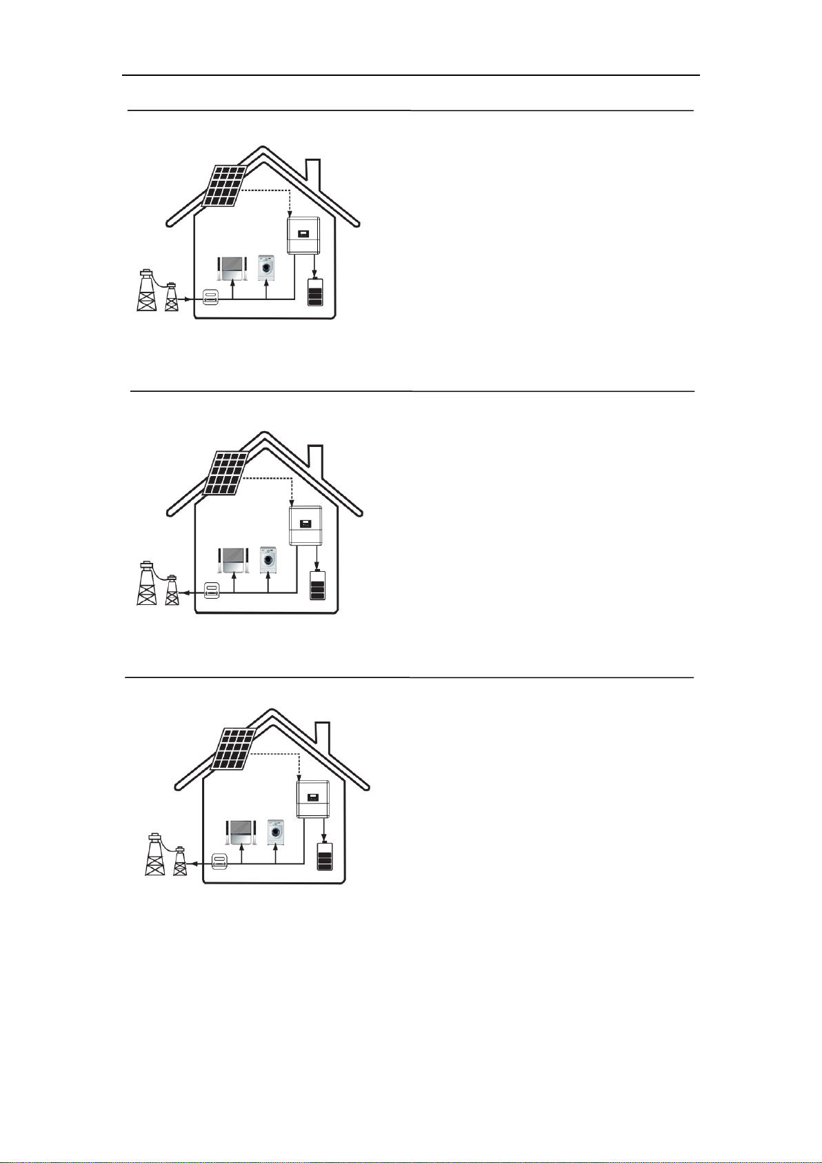
3.2 Work Modes
TSOL Series inverter provides multiple work modes based on different requirements.
Work mode: Self-use (with PV Power)
Priority: load>battery>grid
This mode applies the area that has low
feed-in tariff and high energy price.
The power generated fromPV will be used to
supply the local loads firstly, then to charge the
battery. The redundant power will export to the
public grid.
Work mode: Self-use (without PVPower)
When no PV supplied, battery will discharge
for localloads firstly, and grid will supply power
when the battery capacity is not enough.
Note!
Please control the home loads, and make sure it‟s within the “EPS output
rating” under EPS mode, otherwise the inverter will shut down with an
“overload fault” warning.
Please confirm with the mains grid operator whether there are any special
regulations for grid connection.
13
Work mode: Back up mode
Priority: battery>load>grid
This mode applies the area that has frequent
power outages. And this mode ensures the
battery will has enough energy to supply
when the grid is off.
In this mode battery will be charging
forcibly in the setting time and will never
be discharged when the grid is on, and it
also allows to choose whether charge
from the grid or not.
Work mode: Feed in Priority
Priority: load>grid>battery
This mode applies the area that has high
feed-in tariff and export control.
The PV generated power will be used to
supply the localloads firstly, then export to
the public grid. The redundant power will
charge the battery.
Work mode: Force time use
Priority: battery>load>grid (when charging)
Priority: load>battery>grid (when
discharging)
This mode applies the area that has electricity
price between peak and valley. User can use
off-peak electricity to charge the battery.
The charging and discharging time can be set
flexibly, and it also allows to choose whether
charge from the grid or not.

14
3.3 Dimension
*EPS Status
When the grid is off, system will supply
emergency power from PV or battery to
supply the home loads. (Battery is
necessary in EPS mode.)
Work mode: Peak and valleymode
Priority: battery>load>grid(when
charging)
Priority: load>grid(whendischarging)
Charge the battery according to the set
power within the set charging time; During
the set discharge time, the battery is
discharged according to the set power.
Other time according to Self Use mode.

15
3.4 Terminals of PV inverter
Object
Description
A
DC switch (optional)
B
PV connection area
C
Battery connection area
D
Waterproof valve
E
EPS output
F
GRID output
G
BMS/Meter
H
DI/DO
I
WiFi/RF port for external Pocket WiFi/RF
Warning!
Qualified electrician will be required for the installation.

16
4 Technical Data
4.1 DC input
Model
TSOL-H3
.0K-H
TSOL-H3
.6K-H
TSOL-H4
.0K-H
TSOL-H4
.6K-H
TSOL-H5
.0K-H
TSOL-H6
.0K-H
Max. recom mended DC power [W]
5000
5500
6000
6500
7000
7200
Max. DC voltage[V]
620
Nominal DC operatingvoltage[V]
360
MPPT voltage range[V]
100-560
MPPT voltage range @full load [V]
165-500
200-500
220-500
250-500
270-500
320-500
Max. input current[A]
10/10
Max. shortcircuit current [A]
12/12
Start inputvoltage [V]
85
Start outputvoltage [V]
125
No. of MPP trackers
2
Strings perMPP tracker
1
Back feed currentto PV array
0
DC disconnection switch
optional
4.2 AC output / input
Model
TSOL-H3.
0K-H
TSOL-H3.
6K-H
TSOL-H4.
0K-H
TSOL-H4.
6K-H
TSOL-H5.
0K-H
TSOL-H6.
0K-H
AC output
Nominal AC power[W]
3000
3680
4000
4600
5000
6000
Max. apparentAC power[VA]
3000
3680
4000
4600
5000
6000
Ratedgrid voltage(range)[V]
220/230/240 (180 to 270)
Ratedgrid frequency[Hz]
50/60
Nominal ACcurrent [A]
13
16
17.3
20
21.7
26.1
Max.AC current [A]
14
17.2
18.6
21.4
23.2
27.9
Displacementpowerfactor
0.8 leading...0.8 lagging
Total harmonicdistortion (THDI)
< 3%
Loadcontrol
optional
AC input
Max. apparentAC power[VA] (O&U
Version)
3000
3680
4000
4600
5000
6000
Max. apparentAC power[VA] (I
Version)
3000+3000
(bypass)
3680+3680
(bypass)
4000+4000
(bypass)
4600+4600
(bypass)
5000+5000
(bypass)
6000+6000
(bypass)
Ratedgrid voltage (range)[V]
220/230/240 (180 to 270)
Ratedgrid frequency[Hz]
50/60
Nominal ACcurrent [A] (O&U
Version)
13
16
17.3
20
21.7
26.1
Max.AC current [A] (O&U Version)
14
17.2
18.6
21.4
23.2
27.9
Nominal ACcurrent [A] (I Version)
13+13
(bypass)
16+16
(bypass)
17.3+17.3
(bypass)
20+20
(bypass)
21.7+21.7
(bypass)
26.1+26.1
(bypass)
Max. AC current [A] (I Version)
14+14
(bypass)
17.2+17.2
(bypass)
18.6+18.6
(bypass)
21.4+21.4
(bypass)
23.2+23.2
(bypass)
27.9+27.9
(bypass)
Displacementpowerfactor
0.8 leading...0.8 lagging
AC inrushcurrent[A]
35
AC maximum outputfaultcurrent [A]
80
This manual suits for next models
5
Table of contents
Other TSUNESS Inverter manuals


